EP1036669A1 - Appareil destiné à l'application de couvertures rigides et souples sur des documents reliés ou non reliés - Google Patents
Appareil destiné à l'application de couvertures rigides et souples sur des documents reliés ou non reliés Download PDFInfo
- Publication number
- EP1036669A1 EP1036669A1 EP00110961A EP00110961A EP1036669A1 EP 1036669 A1 EP1036669 A1 EP 1036669A1 EP 00110961 A EP00110961 A EP 00110961A EP 00110961 A EP00110961 A EP 00110961A EP 1036669 A1 EP1036669 A1 EP 1036669A1
- Authority
- EP
- European Patent Office
- Prior art keywords
- binding
- pages
- lever
- deforming
- shaped channel
- Prior art date
- Legal status (The legal status is an assumption and is not a legal conclusion. Google has not performed a legal analysis and makes no representation as to the accuracy of the status listed.)
- Withdrawn
Links
- 238000000034 method Methods 0.000 claims abstract description 7
- 239000011800 void material Substances 0.000 claims 1
- 230000007246 mechanism Effects 0.000 abstract description 8
- 229910000831 Steel Inorganic materials 0.000 description 9
- 239000010959 steel Substances 0.000 description 9
- 239000000463 material Substances 0.000 description 4
- 238000002788 crimping Methods 0.000 description 3
- 230000000994 depressogenic effect Effects 0.000 description 3
- 230000001131 transforming effect Effects 0.000 description 3
- 239000000853 adhesive Substances 0.000 description 2
- 230000001070 adhesive effect Effects 0.000 description 2
- 239000011230 binding agent Substances 0.000 description 2
- 230000008275 binding mechanism Effects 0.000 description 2
- 230000006835 compression Effects 0.000 description 2
- 238000007906 compression Methods 0.000 description 2
- 230000001419 dependent effect Effects 0.000 description 2
- 238000004519 manufacturing process Methods 0.000 description 2
- 230000000717 retained effect Effects 0.000 description 2
- 229910000639 Spring steel Inorganic materials 0.000 description 1
- 230000003466 anti-cipated effect Effects 0.000 description 1
- 238000005452 bending Methods 0.000 description 1
- 239000004744 fabric Substances 0.000 description 1
- 239000002783 friction material Substances 0.000 description 1
- 230000003993 interaction Effects 0.000 description 1
- 230000013011 mating Effects 0.000 description 1
Images





Classifications
-
- B—PERFORMING OPERATIONS; TRANSPORTING
- B42—BOOKBINDING; ALBUMS; FILES; SPECIAL PRINTED MATTER
- B42B—PERMANENTLY ATTACHING TOGETHER SHEETS, QUIRES OR SIGNATURES OR PERMANENTLY ATTACHING OBJECTS THERETO
- B42B5/00—Permanently attaching together sheets, quires or signatures otherwise than by stitching
- B42B5/06—Permanently attaching together sheets, quires or signatures otherwise than by stitching by clips
-
- Y—GENERAL TAGGING OF NEW TECHNOLOGICAL DEVELOPMENTS; GENERAL TAGGING OF CROSS-SECTIONAL TECHNOLOGIES SPANNING OVER SEVERAL SECTIONS OF THE IPC; TECHNICAL SUBJECTS COVERED BY FORMER USPC CROSS-REFERENCE ART COLLECTIONS [XRACs] AND DIGESTS
- Y10—TECHNICAL SUBJECTS COVERED BY FORMER USPC
- Y10T—TECHNICAL SUBJECTS COVERED BY FORMER US CLASSIFICATION
- Y10T29/00—Metal working
- Y10T29/49—Method of mechanical manufacture
- Y10T29/49815—Disassembling
- Y10T29/49822—Disassembling by applying force
-
- Y—GENERAL TAGGING OF NEW TECHNOLOGICAL DEVELOPMENTS; GENERAL TAGGING OF CROSS-SECTIONAL TECHNOLOGIES SPANNING OVER SEVERAL SECTIONS OF THE IPC; TECHNICAL SUBJECTS COVERED BY FORMER USPC CROSS-REFERENCE ART COLLECTIONS [XRACs] AND DIGESTS
- Y10—TECHNICAL SUBJECTS COVERED BY FORMER USPC
- Y10T—TECHNICAL SUBJECTS COVERED BY FORMER US CLASSIFICATION
- Y10T29/00—Metal working
- Y10T29/53—Means to assemble or disassemble
- Y10T29/53796—Puller or pusher means, contained force multiplying operator
- Y10T29/53835—Puller or pusher means, contained force multiplying operator having wedge operator
Definitions
- This invention is directed generally to the binding and unbinding of books and in particular is concerned with improvements in the manner which hard and soft back covers are secured to and released from the pages of a book.
- Sheet binding is one of the oldest known arts, and numerous methods and apparatuses are known in the art for permanently or temporarily securing sheets together. Most of these known methods and apparatus are only economically suited for high priced or high volume commercial printing operations.
- US-A-4,986,713 to Zoltner et al. describes a novel apparatus for applying preformed hard or soft covers to bound or unbound documents, provides a solution to many of these problems.
- this apparatus is still too complicated and uneconomical for the average business office environment.
- this apparatus is poorly suited to very small(1-10) document sets and, due to its complexity, is susceptible to failure due to accidental misuse.
- the individual parts of the device must be robust enough to withstand the high forces generated within the Zoltner et al. device during the binding of a book. Consequently, the Zoltner et al. device is heavy and its parts are expensive both in materials and production costs. Finally, it is difficult for the average person to operate due to the high forces (up to 70 lbs (32kg)) which must be applied to a handle during the binding operation.
- EP-A-477,556 discloses an apparatus and method for binding pages together to form books, using hard or soft cover cases and a channel binder. Once adhesive has been applied to the back of a cover case, a channel is placed on the adhesive, and the channel is clamped to bind pages in the cover case.
- NL-B-35197 discloses a device to keep pages together in the form of a book.
- a clip device located at one edge of the pages, at the top and bottom, clamps the pages together with a cover page.
- the present invention provides a binding apparatus for binding a plurality of pages with a U-shaped channel member, comprising:
- the present invention also provides a method for binding a plurality of pages into a channel member, characterized by the steps of:
- the deforming means further comprise a fixed jaw; a movable jaw; and connection means for movably connecting the fixed and movable jaws.
- the deforming means may include biasing means for biasing the movable jaw away from the fixed jaw.
- the deforming means further comprises a movable support bed pivotably connected to the connection means. The support bed may be movable relative to the fixed and movable jaws, and is pivotably connected to the connection means.
- each lever arm is determined by controlling one of a width and a thickness of each lever arm.
- the binding apparatus has pivoting means comprising: a cam shaft rotatably supported by the lever means, the cam rotationally-fixed to the cam shaft; and a pinion gear supported on and rotationally-fixed to the cam shaft.
- the actuating means includes a sector gear, rotatably supported on the lever means and engaged with a pinion gear; an actuator arm engageable with the sector gear; a spring connected at a first end to the actuator arm; and a spring link connected at a first end to a second end of the spring and at a second end to the handle, wherein when the handle is moved from the first position to the second position, the actuator arm moves laterally causing the sector gear to rotate, thereby causing the pivoting means to rotate the cam.
- the spring expands such that the actuator arm does not move and the cam remains stationary, and the lever means expand, forcing the deforming means from the preparatory position to a deforming position, thereby deforming the U-shaped channel.
- the gear ratio of the pinion gear to the sector gear is 10 to 1.
- the deforming means comprises a jaw means for crimping the U-shaped channel.
- the jaw means comprise a fixed jaw; a movable jaw; a support bed; and connection means for movably connecting the fixed and movable jaws.
- the deforming means may further comprise biasing means for biasing the movable jaw away from the fixed jaw.
- the deforming means further comprise a fixed jaw; a movable jaw; and connection means for movably connecting the fixed and movable jaws.
- the deforming means may include biasing means for biasing the movable jaw away from the fixed jaw.
- the deforming means further comprises a movable support bed pivotably connected to the connection means. The support bed may be movable relative to the fixed and movable jaws, and is pivotably connected to the connection means.
- each lever arm is determined by controlling one of a width and a thickness of each lever arm.
- the binding apparatus has pivoting means comprising: a cam shaft rotatably supported by the lever means, the cam rotationally-fixed to the cam shaft; and a pinion gear supported on and rotationally-fixed to the cam shaft.
- the actuating means includes a sector gear, rotatably supported on the lever means and engaged with a pinion gear; an actuator arm engageable with the sector gear; a spring connected at a first end to the actuator arm; and a spring link connected at a first end to a second end of the spring and at a second end to the handle, wherein when the handle is moved from the first position to the second position, the actuator arm moves laterally causing the sector gear to rotate, thereby causing the pivoting means to rotate the cam.
- the spring expands such that the actuator arm does not move and the cam remains stationary, and the lever means expand, forcing the deforming means from the preparatory position to a deforming position, thereby deforming the U-shaped channel.
- the gear ratio of the pinion gear to the sector gear is 10 to 1.
- the deforming means comprises a jaw means for crimping the U-shaped channel.
- the jaw means comprise a fixed jaw; a movable jaw; a support bed; and connection means for movably connecting the fixed and movable jaws.
- the deforming means may further comprise biasing means for biasing the movable jaw away from the fixed jaw.
- the force transmitting means may comprise: a cam shaft pivotably supported by the lever means; a cam fixedly connected to the cam shaft, a bearing surface of the cam contacting the jaw means; and a pinion gear, wherein in the first phase of operation the cam shaft is pivoted to an adjusting position, thereby moving the jaw means adjacent the U-shaped channel, and in the second phase of operation the cam remains in the adjusting position, and moves laterally with the lever means as the lever means is forced apart to apply the crimping force to the jaw means.
- the adjusting means may further comprise: a sector gear rotatably supported on the lever means, and engaged with a gear means of the force transmitting means; an actuator arm engageable with the sector gear; a spring connected at a first end to the actuator arm and at a second end to a spring link; a second end of the spring link connected to the lever expanding means; wherein in the first phase of operation, the lever expanding means are moved from a first position to a second position, thereby moving the actuating arm laterally to rotate the sector gear, thereby rotating the force transmitting means to move the jaw means to the preparatory position.
- the binding apparatus may further comprise a debinding apparatus, the debinding apparatus comprising: a debinding force transforming means, engageable with the deforming means, for transforming the binding force to a debinding force; and wedge means, engageable with the debinding force transforming means, for uncrimping the U-shaped channel member upon an application of the debinding force.
- a debinding force transforming means engageable with the deforming means, for transforming the binding force to a debinding force
- wedge means engageable with the debinding force transforming means, for uncrimping the U-shaped channel member upon an application of the debinding force.
- Figures 1 and 2 show a top and side view, respectively, of the preferred embodiment of the binder apparatus 20.
- the handle 22 when in a substantially horizontal position, is in a binding position.
- the movable jaw 42b When in the binding position, the movable jaw 42b is moved towards the fixed jaw 42a such that a book 80 supported by book supports 24 is forced into a bound condition.
- the book 80 comprises pages 82 which are to be bound and the book cover assembly 84.
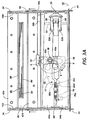
- the number of pages 82 which can be bound by the binding apparatus 20 is in the range of 5 to 1,000, and is determined by the maximum width of the gap between the fixed jaw 42a and the movable jaw 42b and the amount of motion provided by the flat cam 58 (Figs. 3A-3D) of the mechanism assembly.
- the binding apparatus 20 is constructed to bind between 10 and 200 pages.
- the book cover assembly 84 is formed by connecting two hard covers 88 to a U-shaped soft steel channel member 86 with a paper or fabric spine member 92.
- the spine member 92 covers the outer surface of hard covers 88, wrapping around their edges.
- Heavy paper face plates 90 are attached to the outside edges of the hard covers 88.
- the pages 82 to be bound are placed into the U-shaped channel member 86 along with the free ends of the face plates 90. After the pages 82 are squared up and centered in the U-shaped channel member 86, the unbound book 80 is placed onto the support bed 46 of the binding apparatus 20.
- the handle 22 is in an upright, non-binding position as shown in Figure 2.
- the handle 22 is moved from the vertical non-binding position shown in Figure 1 to the horizontal binding position shown in Figure 2.
- the movable jaw 42b is moved towards the fixed jaw 42a such that the U-shaped channel member 86 is bent inwardly, catching and compressing the pages 82.
- the jaws 42a and 42b bear against the U-shaped channel member 86 through the spine member 92 at approximately the top quarter of the length of the uprights 86a of the U-shaped channel member 86.
- the U-shaped channel member 86 is made of soft steel (as opposed to spring steel)
- the force of the jaws 42a and 42b plasticly deform the U-shaped channel member.
- the paper pages 82 and face plates 90 are compressed between the approaching uprights 86a of the U-shaped channel member 86.
- the plasticly deformed soft steel U- shaped channel member 86 undergoes a minimal amount of elastic spring back.
- the pages 82 were also compressed during the binding operation, they also elasticly spring back, thereby ensuring that the pages 82 are securely bound within the U-shaped channel member 86.
- the binding stroke of the movable jaw 42b is less than the full amount of stroke necessary to completely bind the book 80. This reduced binding stroke minimizes the force necessary to move the handle 22 from the vertical non-binding position to the horizontal binding position.
- multiple strokes of the movable jaw 42b against the U-shaped channel member 86 are required.
- the movable jaw 42b must begin its next binding stroke at essentially the same position where it ended the previous binding stroke, up to the point at which the U-shaped channel member 86 is completely plasticly deformed such that no further compression of the pages 82 is possible, thereby completely binding the book 80.
- the second ends of the scissor bars 48a and 48b are rotatably connected to the fixed and movable jaws 42a and 42b by two additional shoulder screws 47, as shown in Figure 4A.
- the scissor springs 44a and 44b are connected to the scissor bars 48a and 48b and bed assembly pins 45. The symmetrical motion of the springs 44a and 44b keeps the bed centered with respect to the jaws 42a and 42b during the first phase of operation.
- the scissor springs 44a and 44b provide a biasing force for forcing the movable jaw 42b away from the fixed jaw 42a towards the fully open position.
- the amount of travel of the movable jaw 42b is determined by the shape of cam 58 and the amount of cam rotation provided for by stops 62b and 62c. In the fully closed position, the jaw frame is also restricted by the slots provided in frame members 102 and 104. Alternatively, the amount of travel of movable jaw 42b can be determined by the length of the voids 49, with the shoulder screws 47 bearing against the outer edge of the voids 49 when the movable jaw is at its fully open position and against the inner edge of the voids 49 when the movable jaw 42b is in its fully closed position.
- a flat cam 58 rides against a wear plate 72 provided on the movable jaw 42b.
- the flat cam 58 has its flat non-bearing portion 58a closest to and perpendicular to the handle such that point A of the bearing surface 58b of flat cam 58 is in contact with the wear plate 72.
- a pinion/stop assembly 62 having a pinion gear 62a and stops 62b and 62c is fixedly connected by a cam shaft 78 to the flat cam 58.
- the pinion gear 62a meshes with a sector gear 60.
- the sector gear 60 is an arcuate sector of a circular gear.
- the sector gear 60 provides for a 1:10 gear ratio to the pinion gear.
- the sector gear provides an arc in the range of 5° to 30° of an entire 360° gear.
- the flat cam provides for a corresponding arc in the range of rotation between 50° and 300°.
- the sector gear is 18° in arc and the flat cam 58 provides for a corresponding amount of rotation of at least 180°.
- the mechanism assembly 50 provides for a two-stage binding operation each time the handle 22 is moved from the vertical non-binding position to the horizontal binding position.
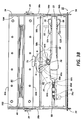
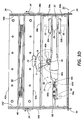
- the movable jaw 42b is rapidly moved towards the fixed jaw 42a to firmly grasp the book 80, as shown in Figures 3B and 3D.
- the handle 22 has been depressed approximately one quarter of the way from the vertical position to the horizontal position, causing the flat cam 58 to rotate from bearing against the wear plate at point A on the bearing surface 58a to bearing at point B on the bearing surface 58a of the flat cam 58.
- the point B represents the amount of rotation the flat cam 58 must undergo to adjust the movable jaw 42b from the fully open position to a binding position.
- the particular amount of rotation of flat cam 58 required to adjust the movable jaw 42b to contact any particular book 80 is necessarily dependent upon the particular thickness of the book 80. Accordingly, the exact position of the point B and the position of the handle necessary to move the flat cam 58 to the point B is dependent upon the thickness of the book as well.
- Figures 3A-3D show a top view of a mechanism assembly 50, with the flat cam 58, the sector gear 60, the pinion gear 62a and a retaining spring 68 (shown in hidden line when necessary) under the upper lever arms 54a and 54b.
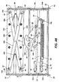
- Figures 4A-4B show a plan bottom view of the mechanism assembly 50 with the flat cam 58 again shown in hidden line above the lower lever arms 54c and 54d (when necessary), while the sector gear 60, the pinion-stop assembly 62, the stop link 64, the actuating spring 66 and the actuator arm 70 are visible.
- the flat cam 58 is fixedly supported on the cam shaft 78 between the left side lever arms 54a and 54c.
- the cam shaft 78 extends below the lower lever arm 54c to provide a notch portion for fixedly supporting the pinion-stop assembly. A further portion of the cam shaft 78 extends downwardly for retaining a first end of the stop link 64. A first pair of holes are provided in the left lever arms 54a and 54c and the cam shaft 78 is rotatably supported therein.
- the gear end 60a of the sector gear 60 engages the pinion gear 62a of the pinion-stop assembly 62, and pivots at its second end 60b on sector post 77.
- the pinion-stop assembly 62 and sector gear 60 lie below the lower lever arms 54c and 54d.
- the stop link 64 connects to the sector post 77 and the cam shaft 78 to both hold the pinion-stop assembly 62 and a sector gear 60 onto their respective shafts and to provide a bearing surface for the stops 62b and 62c.
- the stop 62b is arranged on the stop assembly 62 so that when the handle is moved toward the vertical non-binding position, the flat cam 58 can rotate only as far as point A.
- the second stop 62c is arranged on the pinion-stop assembly 62 so that the flat cam 58 can be rotated no further than a point E, which represents position of the flat cam 58 for a complete bind for a minimal number of pages 82 in the book 80.
- an actuator arm 70 and actuating spring 66 are used to connect the handle 22 to the sector gear 60.
- the actuator spring 66 is connected to the handle 22 by means of the spring link 76 and the spring pin 75.
- the other end of the actuating spring 66 is attached to the actuator arm 70 at tab 70a.
- the actuator arm 70 is then connected to the sector gear 60 by means of a slot in a sidewall of the actuator arm 70, which is mated with a third end 60c of the sector gear 60.
- the third end 60c extends from the second end 60b of the sector gear 60 at a generally right angle to the gear end 60a of the sector gear 60.
- a free end of the third end 60a of the sector gear has a trapezoidal notch 60d formed therein for mating with the slot in the actuating arm 70.
- a retaining hole is provided inside of the trapezoidal notch 60d.
- the retaining spring 68 is attached to the sector gear 60 by means of the retaining hole.
- the other end of the retaining spring 68 is attached to the vertical section of tab 70a of actuating arm 70 as shown in Figs. 3A-3D and 4A-4B.
- the spring pin 75 is rotated away from the sector gear 60. Due to the high spring force of the actuating spring 66, the actuating spring 66 during the first phase of operation acts as a rigid link, pulling the actuator arm 70 towards the handle 22. The back edge of the slot in the actuating arm 70 engages the trapezoidal notch 60d in the third end 60c of the sector gear 60 causing the sector gear 60 to rotate counter-clockwise about the sector post 77.
- the binding force is provided by the interaction between the face cams 52a and 52b and the six rollers 56.
- the six rollers 56 are divided into three pairs of rollers, which are set into handle 22 and circumferentially spaced at 120° intervals around the pivot shaft 55.
- the face cams 52a and 52b are provided with three sets of ramps and stops. As shown in Fig. 7, the sets of ramps and stops of the face cams 52a and 52b are also distributed at 120° intervals around the pivot shaft 55 and provide a bearing surface for the rollers 56. As shown in Figure 3A, and for each set of rollers 56, the rollers 56 bear against each other and the ramps of the face cams 52a and 52b.
- the handle 22 does not absorb any of the binding force, and can be made of material merely strong enough to hold the rollers 56 in a fixed position relative to the handle as the handle is moved to and from the binding position.
- the face cams 52a and 52b are slotted on their faces away from the handle 22, so that the face cams 52a and 52b can be fitted onto the lever arms 54a, 54c and 54b, 54d, respectively.
- the total amount of expansion of the lever arms 54a-54d is provided by the face cams 52a and 52d and rollers 56.
- Each set of left or right lever arms provides about one-half (3.5mm-4.5mm) of the expansion. This amount of expansion is further reduced by the lever ratio between the pivot point of the cam shaft 78 and the pivot point of the face cams about the pivot shaft 55. In the preferred embodiment, the lever ratio is approximately 1:2.
- the retaining spring 68 pulls the sector gear clockwise, forcing the actuating arm 70 away from the handle 22.
- the sector gear 60 rotates clockwise, causing the flat cam 58 to rotate counter-clockwise to its initial point A.
- the lever arms 54a-54d have additional cut-outs, as shown in Figures 3C- 3D and 4A-4B, so that they are not perfectly rigid in the horizontal plane.
- the shapes of the cut-out portions are determined according to the particular lever arm flexibility requirements of the design, in order to increase the flexibility of the lever arms 54a-54d.
- the flexibility of the lever arms 54a-54d can be controlled by determining the thickness of the lever arms rather than the width. Accordingly, the lever arms 54a and 54c will flex between the cam shaft 78 and the pivot shaft 55, while the lever arms 54b and 54d will flex over their entire length.
- lever arms 54a- 54d cannot be made so flexible such that they flex (more than a minimal amount) during a normal binding operation and interfere with the application of the binding force by the movable jaw 42b against the U-shaped channel member 86.
- the binding apparatus 20 also includes a debinding apparatus 30 which is detachable connectable to the movable jaw 42b. Accordingly, the handle 22 and mechanism assembly 50 can be used to provide the binding operation as well as a debinding operation described below.
- the debinding apparatus 30 comprises a wedge 32 having a wedge head 32a and a wedge support 32b, a pair of debinder arms 34 located outside of the front frame member 102 and the rear frame member 104, a pair of guide members 36 located between the debinder arms 34 and the front and rear frame members 102 and 104 and a pair of pawls 38a.
- the pawls 38a are pivotably supported on a pawl rod 38b.
- the guides 36 and the debinder arms 34 and front and rear frame members 102 and 104 are provided with slots through which the movable jaw 42b extends.
- the movable jaw 42b When the debinder apparatus 30 is in a non-debinding position, as shown in Figure 5A, the movable jaw 42b is free to move within the slots provided in the debinder arms 34 without contacting them. Also in this position, the pawl 38a is retained in a non-racheting position by a clip portion 36a formed in guide 36. The wedge 32 is stored in an upright position in wedge retaining portions 34b formed in the right-most ends of the debinder arms 34.
- the debinder arms 34 are moved to the right as shown in Figure 5B, so that they extend beyond the right hand edge of the front and rear frame members 102 and 104.
- a pawl releasing portion 34c formed in the debinder arm 34 contacts the pawl 38a and forceably releases it from the clip portion 36a.
- the pawl 38a engages a teeth portion 34a formed on the debinder arm 34.
- the pawls 38a engages the leftmost teeth of the teeth portions 34a.
- the book 80 is inserted horizontally between the debinder arms 34.
- the book 80 is opened at approximately the center point of the pages 82, and the wedge 32 is inserted therein so that it lies within the wedge retaining portions 34b of the retaining arms 34.
- Each wedge retaining portion 34b has a front overhang and a rear overhand, such that when the wedge 32 is inserted therein, the wedge support 32b lies under each of the overhangs. This ensures that the wedge 32 remains in a horizontal position during the debinding operation.
- the wedge can be moved forward slightly so that the wedge support 32b no longer lies underneath the rear overhangs and can be removed from the wedge retaining portion 34b.
- the handle 22 is depressed from the non-binding position to the binding position, thereby forcing the movable jaw 42b towards the fixed jaw 42a, as described above.
- the movable jaw 42b moves towards the fixed jaw 42a, it engages the debinder arms 34, forcing them leftwards.
- the wedge retaining portions 34b engage the wedge support 32b and force the wedge 32 leftwards, thereby forcing the book 80 leftwards.
- the book 80 is forced leftwards, it encounters the front and rear frame members 102 and 104 (and a vertical portion of the cover 26) such that it cannot continue to move leftwards.
- the wedge head 32a of the wedge 32 is forced between the uprights 86a of the U-shaped channel member 86, causing them to spread outwardly. It is important to note that the wedge head 32a must be steep enough in order to generate a sufficient amount of spread in the U- shaped channel member 86 to release the bound pages 82. It is also important to note that the wedge head 32a of the wedge 32 must also have a very low coefficient of friction on its bearing surface, in order to avoid crushing or bending any of the pages 82. That is, the coefficient of friction between any two pages 82 must always be greater than the largest possible coefficient of friction between the wedge head 32a and the pages 82. Accordingly, it is anticipated in the preferred embodiment that the wedge head 32a will be made with Acetel or a like low friction material.
- the handle 22 After the handle 22 has reached the full binding position, it is returned to the vertical non-binding position, the debinder arms 34 having been forced a small distance to the left.
- the pawls 38a engage the teeth portions 34a to prevent the debinder arms 34 from moving back to the right.
- Each subsequent operation of the handle 22 towards the binding position forces the movable jaw 42b and, therefore the debinder arm 34, further to the left, progressively forcing the U-shaped channel member apart as the wedge 32 is drawn deeper into the U-shaped channel member 86.
- the wedge head 32a will contact the bottom of the U-shaped channel member 86, thereby fully debinding the pages 82 from the book 80.
- the wedge 32 and book 80 are removed from the wedge retaining portion 34b and the debinder arms 34 are pushed to the left, moving them to their non-binding position.
- the pawls 38a which are designed solely to hold the debinder arms 34 against a rightward force, click over the teeth 34a and are eventually forced by edges 34d of the debinder arms 34 back into the retaining position where they are retained by the clip portions 36a of the guides 36.
- the same binding mechanism 20 used to bind the books 80 can be used to debind the books 80, without resort to additional intricate or complicated link members.
Landscapes
- Engineering & Computer Science (AREA)
- Textile Engineering (AREA)
- Basic Packing Technique (AREA)
- Folding Of Thin Sheet-Like Materials, Special Discharging Devices, And Others (AREA)
- Sheet Holders (AREA)
- Microscoopes, Condenser (AREA)
- Diaphragms For Electromechanical Transducers (AREA)
- Sampling And Sample Adjustment (AREA)
Applications Claiming Priority (3)
| Application Number | Priority Date | Filing Date | Title |
|---|---|---|---|
| US928554 | 1992-08-11 | ||
| US07/928,554 US5226771A (en) | 1992-08-11 | 1992-08-11 | Apparatus and method for applying hard and soft covers to bound or unbound documents |
| EP93919963A EP0680410B1 (fr) | 1992-08-11 | 1993-08-11 | Appareil ameliore destine a l'application de couvertures rigides et souples sur des documents relies ou non relies |
Related Parent Applications (1)
| Application Number | Title | Priority Date | Filing Date |
|---|---|---|---|
| EP93919963A Division EP0680410B1 (fr) | 1992-08-11 | 1993-08-11 | Appareil ameliore destine a l'application de couvertures rigides et souples sur des documents relies ou non relies |
Publications (1)
| Publication Number | Publication Date |
|---|---|
| EP1036669A1 true EP1036669A1 (fr) | 2000-09-20 |
Family
ID=25456412
Family Applications (2)
| Application Number | Title | Priority Date | Filing Date |
|---|---|---|---|
| EP00110961A Withdrawn EP1036669A1 (fr) | 1992-08-11 | 1993-08-11 | Appareil destiné à l'application de couvertures rigides et souples sur des documents reliés ou non reliés |
| EP93919963A Expired - Lifetime EP0680410B1 (fr) | 1992-08-11 | 1993-08-11 | Appareil ameliore destine a l'application de couvertures rigides et souples sur des documents relies ou non relies |
Family Applications After (1)
| Application Number | Title | Priority Date | Filing Date |
|---|---|---|---|
| EP93919963A Expired - Lifetime EP0680410B1 (fr) | 1992-08-11 | 1993-08-11 | Appareil ameliore destine a l'application de couvertures rigides et souples sur des documents relies ou non relies |
Country Status (8)
| Country | Link |
|---|---|
| US (1) | US5226771A (fr) |
| EP (2) | EP1036669A1 (fr) |
| JP (1) | JPH08500303A (fr) |
| AU (1) | AU667967B2 (fr) |
| CA (1) | CA2142180C (fr) |
| DE (1) | DE69329803T2 (fr) |
| ES (1) | ES2156874T3 (fr) |
| WO (1) | WO1994004374A1 (fr) |
Cited By (1)
| Publication number | Priority date | Publication date | Assignee | Title |
|---|---|---|---|---|
| WO2002058940A1 (fr) * | 2001-01-24 | 2002-08-01 | Esselte N.V. | Procede et appareil de reliure |
Families Citing this family (7)
| Publication number | Priority date | Publication date | Assignee | Title |
|---|---|---|---|---|
| US5364216A (en) * | 1993-05-07 | 1994-11-15 | Xerox Corporation | Apparatus for applying a binding strip to document sets |
| USD365580S (en) | 1994-10-11 | 1995-12-26 | Unicoil, Inc. | Spiral binding apparatus |
| US5730571A (en) * | 1995-06-07 | 1998-03-24 | Gunther International, Ltd. | Apparatus for binding documents utilizing slip binders |
| AU2003223419A1 (en) * | 2002-04-02 | 2003-10-20 | Channelbind International Corporation | Improved apparatus and method for applying hard and soft covers to bound or unbound documents |
| DE102007024636A1 (de) * | 2007-05-24 | 2008-11-27 | Esselte Leitz Gmbh & Co. Kg | Bindevorrichtung |
| DE102008034404A1 (de) * | 2008-07-23 | 2010-01-28 | Esselte Leitz Gmbh & Co. Kg | Bindevorrichtung |
| PL389650A1 (pl) * | 2009-11-23 | 2011-06-06 | Opus Spółka Z Ograniczoną Odpowiedzialnością | Sposób i urządzenie do debindowania oprawionych dokumentów |
Citations (4)
| Publication number | Priority date | Publication date | Assignee | Title |
|---|---|---|---|---|
| NL35197C (fr) * | 1900-01-01 | |||
| US4893836A (en) * | 1988-03-17 | 1990-01-16 | Taurus Holdings, Inc. | Book binding connector and binding-debinding tool |
| US4986713A (en) * | 1989-06-20 | 1991-01-22 | Xerox Corporation | Apparatus for applying hard and soft covers to bound or unbound documents |
| EP0477556A1 (fr) * | 1990-08-30 | 1992-04-01 | R. R. DONNELLEY & SONS COMPANY | Dispositif et procédé pour l'assemblage d'une couverture et d'un élément de reliure |
Family Cites Families (3)
| Publication number | Priority date | Publication date | Assignee | Title |
|---|---|---|---|---|
| GB8322292D0 (en) * | 1983-08-18 | 1983-09-21 | Murographics Ltd | Binding sheets of paper & c |
| FR2620638A1 (fr) * | 1987-09-22 | 1989-03-24 | Duchene Rene | Agrafage mecanique de toles fortes sans fournitures |
| US4958974A (en) * | 1989-08-07 | 1990-09-25 | Xerox Corporation | Damped binding apparatus |
-
1992
- 1992-08-11 US US07/928,554 patent/US5226771A/en not_active Expired - Lifetime
-
1993
- 1993-08-11 EP EP00110961A patent/EP1036669A1/fr not_active Withdrawn
- 1993-08-11 DE DE69329803T patent/DE69329803T2/de not_active Expired - Lifetime
- 1993-08-11 EP EP93919963A patent/EP0680410B1/fr not_active Expired - Lifetime
- 1993-08-11 JP JP6506371A patent/JPH08500303A/ja not_active Ceased
- 1993-08-11 CA CA002142180A patent/CA2142180C/fr not_active Expired - Fee Related
- 1993-08-11 ES ES93919963T patent/ES2156874T3/es not_active Expired - Lifetime
- 1993-08-11 WO PCT/US1993/007535 patent/WO1994004374A1/fr not_active Ceased
- 1993-08-11 AU AU50048/93A patent/AU667967B2/en not_active Ceased
Patent Citations (4)
| Publication number | Priority date | Publication date | Assignee | Title |
|---|---|---|---|---|
| NL35197C (fr) * | 1900-01-01 | |||
| US4893836A (en) * | 1988-03-17 | 1990-01-16 | Taurus Holdings, Inc. | Book binding connector and binding-debinding tool |
| US4986713A (en) * | 1989-06-20 | 1991-01-22 | Xerox Corporation | Apparatus for applying hard and soft covers to bound or unbound documents |
| EP0477556A1 (fr) * | 1990-08-30 | 1992-04-01 | R. R. DONNELLEY & SONS COMPANY | Dispositif et procédé pour l'assemblage d'une couverture et d'un élément de reliure |
Cited By (1)
| Publication number | Priority date | Publication date | Assignee | Title |
|---|---|---|---|---|
| WO2002058940A1 (fr) * | 2001-01-24 | 2002-08-01 | Esselte N.V. | Procede et appareil de reliure |
Also Published As
| Publication number | Publication date |
|---|---|
| JPH08500303A (ja) | 1996-01-16 |
| DE69329803T2 (de) | 2001-07-19 |
| CA2142180C (fr) | 1998-07-07 |
| AU667967B2 (en) | 1996-04-18 |
| EP0680410A4 (fr) | 1996-01-10 |
| AU5004893A (en) | 1994-03-15 |
| US5226771A (en) | 1993-07-13 |
| WO1994004374A1 (fr) | 1994-03-03 |
| DE69329803D1 (de) | 2001-02-01 |
| CA2142180A1 (fr) | 1994-03-03 |
| EP0680410B1 (fr) | 2000-12-27 |
| EP0680410A1 (fr) | 1995-11-08 |
| ES2156874T3 (es) | 2001-08-01 |
Similar Documents
| Publication | Publication Date | Title |
|---|---|---|
| EP0680410B1 (fr) | Appareil ameliore destine a l'application de couvertures rigides et souples sur des documents relies ou non relies | |
| US5314283A (en) | Apparatus for applying hard and soft covers to bound or unbound documents | |
| US20090056406A1 (en) | Articulated bending brake for sheet metal forming | |
| DE4434513C1 (de) | Vorrichtung zum Biegen drahtartiger Materialien | |
| DE3328660A1 (de) | Reibungsbremse | |
| EP0099249A1 (fr) | Dispositif d'agrafage à fil métallique perfectionné | |
| AU2004315246B9 (en) | Stapler | |
| CN100513170C (zh) | 装订装置 | |
| AU2023258355A1 (en) | Applicator for conveyor belt fasteners | |
| WO2001043898A1 (fr) | Appareil d'assemblage | |
| JP2724686B2 (ja) | テープ送り手段を改良した電気端子アプリケータ | |
| HK1033565A (en) | Apparatus for applying hard and soft covers to bound or unbound documents | |
| US6820787B2 (en) | Stapler | |
| DE60312518T2 (de) | Tischverriegelungssystem für motorgetriebene heftvorrichtungen | |
| EP1655109A1 (fr) | Mecanisme de verrouillage pour plaque de pression d'une agrafeuse | |
| US6641024B2 (en) | Stapling device | |
| WO2003084763A2 (fr) | Ameliorations apportees a un appareil et a un procede d'application de couvertures rigides ou souples sur des documents relies ou non relies | |
| US7544029B2 (en) | Apparatus and method for attaching a cover to an assembly of sheets | |
| PL239197B1 (pl) | Sposób i urządzenie do spinania wielu stronic | |
| DE40243C (de) | Kartonecken - Schliefsmaschine mit selbstthätiger Klammerbildung | |
| WO2002058940A1 (fr) | Procede et appareil de reliure | |
| WO2022094080A1 (fr) | Lits de fixation d'applicateurs d'éléments de fixation de bande transporteuse | |
| JPS588859A (ja) | 間欠送り機構 | |
| WO1996000152A1 (fr) | Appareil de reliure manuelle utilisant des bandes relieuses flexibles |
Legal Events
| Date | Code | Title | Description |
|---|---|---|---|
| PUAI | Public reference made under article 153(3) epc to a published international application that has entered the european phase |
Free format text: ORIGINAL CODE: 0009012 |
|
| AC | Divisional application: reference to earlier application |
Ref document number: 680410 Country of ref document: EP |
|
| AK | Designated contracting states |
Kind code of ref document: A1 Designated state(s): DE ES FR GB IE IT |
|
| 17P | Request for examination filed |
Effective date: 20010305 |
|
| AKX | Designation fees paid |
Free format text: DE ES FR GB IE IT |
|
| 17Q | First examination report despatched |
Effective date: 20020627 |
|
| STAA | Information on the status of an ep patent application or granted ep patent |
Free format text: STATUS: THE APPLICATION IS DEEMED TO BE WITHDRAWN |
|
| 18D | Application deemed to be withdrawn |
Effective date: 20021108 |
|
| REG | Reference to a national code |
Ref country code: HK Ref legal event code: WD Ref document number: 1033565 Country of ref document: HK |