EP1037014A2 - Elektronisches Nivellierinstrument - Google Patents
Elektronisches Nivellierinstrument Download PDFInfo
- Publication number
- EP1037014A2 EP1037014A2 EP00104315A EP00104315A EP1037014A2 EP 1037014 A2 EP1037014 A2 EP 1037014A2 EP 00104315 A EP00104315 A EP 00104315A EP 00104315 A EP00104315 A EP 00104315A EP 1037014 A2 EP1037014 A2 EP 1037014A2
- Authority
- EP
- European Patent Office
- Prior art keywords
- pattern
- light
- leveling rod
- electronic level
- level according
- Prior art date
- Legal status (The legal status is an assumption and is not a legal conclusion. Google has not performed a legal analysis and makes no representation as to the accuracy of the status listed.)
- Granted
Links
Images



Classifications
-
- G—PHYSICS
- G01—MEASURING; TESTING
- G01C—MEASURING DISTANCES, LEVELS OR BEARINGS; SURVEYING; NAVIGATION; GYROSCOPIC INSTRUMENTS; PHOTOGRAMMETRY OR VIDEOGRAMMETRY
- G01C15/00—Surveying instruments or accessories not provided for in groups G01C1/00 - G01C13/00
Definitions
- the present invention relates to an electronic level, and in particular, to an electronic level, which converts a pattern image on a leveling rod to an electric signal by a photoelectric converter and obtains difference of elevation from the electric signal.
- a level is a survey instrument for measuring difference of elevation, and it is conventionally a survey instrument for collimating the leveling rod at a survey target point by an operator with a telescope and for visually reading numerical value given on the leveling rod.
- the electronic level as disclosed in the present invention is a device, which collimates the leveling rod, receives a pattern formed on a photodetection element, calculates the position by converting it to an electric signal, and displays it as a numerical value.
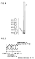
- a first pattern A, a second pattern B, and a third pattern R are repeatedly disposed with equal spacing (p) as shown in Fig. 4. That is, blocks are consecutively disposed, each block having three types of patterns. If the block arranged at the lowest position is defined as 0 block and the patterns are described as R (0), A (0) and B (0), the blocks are repeatedly arranged as R (1), A (1), B (1), R (2), A (2), B (2), .
- a signal corresponding to the spacing can be referred to as a reference signal.
- the third pattern R has a fixed width with black portion width of 8 mm.
- width of black portion is modulated with maximum modulation width in the range of 10 mm so that 600 mm will be one cycle.
- width of the black portion is modulated with maximum modulation width in the range of 10 mm so that 570 mm will be one cycle.
- width of the black portion is modulated so that 600 mm will be one cycle.
- width of the black portion is modulated so that 570 mm will be one cycle. Therefore, the cycle is slightly different between the first pattern A and the second pattern B.
- similar patterns repeatedly appear. In the above example, similar patterns repeatedly appear at 11400 mm, which is the least common multiple of 600 mm and 570 mm. Accordingly, the phase difference between the signal from the first pattern A and the signal from the second pattern B varies between 0 and 2 ⁇ in the range of 0 to 11400 mm.
- a pattern image of the leveling rod 1 is received by a linear sensor.
- the horizontal position H1 can be precisely measured within the equal spacing pitch p (precise measurement).
- the output signal from the linear sensor is integrated with respect to half-pitch before and after the reference signal (signal corresponding to the equal spacing pitch p). Further, the integration value is weeded out at every three values (product detection), and a signal 1 corresponding to the first pattern A, a signal 2 corresponding to the second pattern B, and a signal 3 corresponding to the third pattern R are obtained as shown in Fig. 6.
- width is not modulated in the third pattern R, and, moreover, maximum modulation width is 10 mm in the first pattern A and the second pattern B, while it is only 8 mm in the third pattern R.
- the signal 3 corresponding to the third pattern R has almost constant integration value, and it is about 80% of the value of the signal 1 or the signal 2.
- the third pattern R, the first pattern A and the second pattern B are repeatedly disposed in a predetermined order. Thus, it is possible to determine which of the third pattern R, the first pattern A or the second pattern B is the signal which has been weeded out.
- signals (A ⁇ R) and (B ⁇ R) are obtained as shown Fig. 7 using the signal corresponding to the third pattern R as the reference.
- a set of signals i.e. R, (A ⁇ R) and (B ⁇ R), which include address position (m-th bit) of the linear sensor corresponding to horizontal position and include the reference signal, is selected. If the phases of (A ⁇ R) and (B ⁇ R) are obtained, it is possible to determine at which position of the leveling rod 1 the combination of the first pattern A, the second pattern B, and the third pattern R is located. As a result, approximate level height H2 at the horizontal position can be obtained (crude measurement).
- the level height H can be obtained as follows: Phase of the reference signal at horizontal position is obtained (precise measurement). Further, it is determined at which position the reference signal corresponding to horizontal position is located according to the pattern-starting position of the leveling rod 1 from the phase difference between the first pattern A and the second pattern B (crude measurement). By aligning and matching the horizontal position H1 obtained by precise measurement with the level height H2 obtained by crude measurement, the level height can be obtained.
- the electronic level according to the present invention is an electronic level for converting a pattern on a leveling rod to be collimated by photoelectric conversion and for determining difference of elevation, wherein there is provided an irradiation device for irradiating auxiliary survey light to be projected to the leveling rod by pulsed irradiation.
- the electronic level according to the present invention provides an electronic level as described above, wherein the auxiliary survey light is irradiated in fan-like shape so that a range of the leveling rod to be collimated can be covered.
- the present invention provides an electronic level as described above, wherein a semiconductor laser is provided as a light source for the irradiation device, and a light beam emitted from the semiconductor laser has a larger beam-spreading angle in vertical direction. Further, the present invention provides an electronic level, wherein there is provided a lens for adjusting the beam-spreading angle to suit visual field of a telescope. Also, the present invention provides an electronic level, wherein a photodetection element for receiving reflection light from the leveling rod is provided and a shutter is arranged on the photodetection element, and the shutter is driven in synchronization with the irradiation device.
- the present invention provides an electronic level as described above, wherein a photodetection element for receiving reflection light from the leveling rod is provided and the photodetection element receives the light in synchronization with the pulsed irradiation. Also, the present invention provides an electronic level as described above, wherein a retroreflection sheet is attached on a surface with a pattern of the leveling rod under pulsed irradiation. Further, the present invention provides an electronic level as described above, wherein the retroreflection sheet is a colored reflection sheet. By irradiating the auxiliary survey light as pulsed light, influence of the shade on the reflection surface of the leveling rod can be eliminated. By limiting the reflection light entering the photodetection element using the electronic shutter, S/N ratio can be improved.
- Fig. 1 gives a general view of an electronic level. It comprises an electronic level main unit 3, a sighting device 5 for performing approximate alignment of a target point, a base unit 6 for supporting the electronic level main unit 3 and for performing leveling, an ocular lens unit 7 for collimating a leveling rod 1 for the electronic level positioned at the target point, a focusing knob 8 for performing collimation to the target point, a light projector 9 for projecting auxiliary survey light 11 toward the leveling rod 1 when necessary, an objective lens unit 10 of a telescope where a reflected light from the leveling rod 1 enters, and an operation unit 12 where a power switch and other components are arranged.
- a light source for emitting the auxiliary survey light 11 is automatically or manually operated, for example, when survey operation cannot be performed even though there is sufficient light amount.
- Fig. 2 shows a condition where the auxiliary survey light 11 is projected toward the leveling rod 1 of the electronic level from the projector 9.
- the auxiliary survey light 11 is projected in vertically oblong elliptical shape so that a range can be covered on the collimated leveling rod of the telescope. If it is supposed that a visual field of the telescope is spread over an angle of about 1°30′ and a short distance measurement is to be made for a distance of 1 m and when the telescope and the projector 9 are disposed in parallel to each other, a spreading angle is required, which is spread over an angle of 5° horizontally and about 10° vertically.
- An spreading angle of a beam irradiated from a semiconductor element served as a light source is about 8° horizontally and about 30° vertically. Accordingly, the beam with larger spreading angle should be aligned with the vertical direction, and the spreading in vertical direction should be adjusted.
- It comprises an objective lens unit 10, a compensator 13, a beam splitter 14, an ocular lens unit 7, a CCD linear sensor (photodetection element) 15, an arithmetic processing means 16, and a driving unit 17.
- the objective lens unit 10 is used to form a pattern image of the leveling rod 1 of the electronic level.
- the objective lens unit 10 comprises an objective lens 20 and an internal lens 21.
- the beam can be focused to the pattern image of the leveling rod 1. Therefore, the internal lens 21 corresponds to a focusing unit.
- the compensator 13 is an automatic compensating mechanism for automatically adjusting the line of collimation in horizontal direction, even if the axis of the electronic level main unit 3 is inclined more or less and the image is formed by varying horizontal beam up or down.
- the beam splitter 14 splits the light beam in a direction toward the ocular lens unit 7 and in a direction of the CCD linear sensor 15.
- the ocular lens unit 7 is used by a survey operator to visually observe the leveling rod 1.
- the CCD linear sensor 15 corresponds to a pattern detection unit, and it is used to convert the pattern image of the leveling rod 1 formed by the objective lens unit 10 to an electric signal.
- the CCD linear sensor 15 is used. Any type of sensor can be adopted as the CCD linear sensor 15 so far as it is a linear image sensor where photodiodes are arranged at least uni-dimensionally.
- the arithmetic processing means 16 comprises an amplifier 23, a sample-hold 24, an A/D converter 25, a RAM 26, a clock driver 27, a microcomputer 28, and a display unit 29.
- the amplifier 23 is used to amplify the electric signal from the CCD linear sensor 15, and the sample-hold 24 is used for sample-holding the amplified electric signal using a timing signal from the clock driver 27.
- the A/D converter 25 is used for A/D conversion of the electric signal processed by the sample-hold.
- RAM 26 stores the digital signal obtained from A/D conversion.
- the microcomputer 28 is used for various arithmetic operations.
- the projector 9 comprises a semiconductor laser 31 and a cylindrical lens 32.
- the semiconductor laser 31 is driven and controlled by the microcomputer 28 via the driving unit 17.
- the projector 9, the driving unit 17, the microcomputer 28, etc. constitute an irradiation device, which irradiates the auxiliary survey light 11 to the leveling rod 1 by pulsed irradiation.
- the spreading angle of the auxiliary survey light 11 should be 5° horizontally and about 10° vertically.
- the spreading angle of the beam emitted from the semiconductor element served as the light source is about 8° horizontally and about 30° vertically.
- the cylindrical lens 32 having power in vertical direction is disposed to adjust the vertical spreading angle of the auxiliary survey light 11.
- the auxiliary light 11 is projected toward the leveling rod 1, but there is no need to project the light continuously. It will suffice if there is incident light amount enough to sense and detect for photodetection by the photodetection element, i.e. the CCD linear sensor 15. If the photodetection element is a CCD, the amount of incident light is a product of "electric charge accumulating time" and "illuminance of incident light”. If the photodetection element is an LD with high output, pulsed radiance of several milliseconds will suffice.
- the semiconductor laser 31 is an LD closer to visible light, but no problem occurs if shorter light emission time is set.
- the CCD linear sensor 15 is so designed that it is synchronized with pulsed radiance and receives the light only at light emission. Further, in front of the CCD linear sensor 15, there may be provided an electric shutter 30, which is driven by the driving unit 17 and is opened or closed in synchronization with light emission of the semiconductor laser 31 in order to avoid the receiving of noise light.
- a retroreflection sheet for easier reflection is attached, and a pattern as shown in Fig. 4 is formed on the surface of the retroreflection sheet.
- the pattern formed on the retroreflection sheet can detect collimation light much easier than white-black pattern and it reflects the auxiliary survey light 11 much easier.
- Either the pattern or the plain ground may be designed as a retroreflection surface. Further, it may be designed in such manner that the normal retroreflection sheet looks gray while a colored retroreflection sheet may be used to further increase visibility of the pattern.
- the microcomputer 28 operates the semiconductor laser 31 to emit pulsed radiance via the driving unit 17.
- the semiconductor laser 31 Of the visible light and near infrared light laser beam emitted from the semiconductor laser 31, only vertical components are converged by the cylindrical lens 32, and a light beam in elliptical shape having a spreading angle of 10° vertically and about 8° horizontally is irradiated (See Fig. 2).
- the laser beam emitted from the semiconductor laser 31 has such intensity that it is not influenced by factors such as the tree shade.
- Reflection light reflected by the leveling rod 1 is irradiated through the objective lens unit 10, and it is split into two beams, i.e. a beam directed toward the ocular lens 7 and a beam directed toward the CCD linear sensor 15, by the beam splitter 14.
- the electric shutter 30 is arranged, and it is driven in synchronization with the semiconductor laser 31 and is opened only when the reflection light from the leveling rod 1 enters. As a result, incidence of external light is suppressed, and this leads to the increase of S/N ratio.
- the reflection light enters through the electric shutter 30, and the pattern of the leveling rod 1 as described above is projected on the CCD linear sensor 15.
- the amplifier 23 amplifies the electric signal from the CCD linear sensor 15, and the sample-hold 24 performs sample-holding of the amplified electric signal using the timing signal from the clock driver 27.
- the A/D converter 25 converts the signal to the electric signal, which has been processed by the sample-hold, by A/D conversion.
- the RAM 26 is used to store the digital signal after the A/D conversion.
- the microcomputer 28 calls a photodetection signal from the RAM 26.
- the signal from the photodetection element is processed by Fourier transform or product detection is performed. Further, phase of the reference signal at horizontal position is obtained (precise measurement). Or, from phase difference between a first pattern A and a second pattern B, it is determined at which position the reference signal corresponding to horizontal position is set according to the pattern-starting position of the leveling rod 1 (crude measurement). Then, arithmetic operation is carried out, such as alignment of the horizontal position H1 obtained by the precise measurement with the level height H2 obtained by crude measurement.
- the microcomputer 28 directly measures signal width of each of the first pattern A, the second pattern B and a third pattern R, and performs arithmetic operation to determine which block it corresponds to.
- pulsed auxiliary survey light is projected to the leveling rod so that the influence of factors such as the tree shade can be eliminated in the measurement.
- only required portion of the auxiliary survey light is irradiated by pulsed irradiation, and the system can be operated with low electric power.
- the electronic shutter is driven in response to pulsed radiance, and this makes it possible to withhold and reduce incidence of external light and contributes to the improvement of S/N ratio.
Landscapes
- Physics & Mathematics (AREA)
- Engineering & Computer Science (AREA)
- General Physics & Mathematics (AREA)
- Radar, Positioning & Navigation (AREA)
- Remote Sensing (AREA)
- Length Measuring Devices By Optical Means (AREA)
- Aiming, Guidance, Guns With A Light Source, Armor, Camouflage, And Targets (AREA)
- Measurement Of Optical Distance (AREA)
Applications Claiming Priority (2)
| Application Number | Priority Date | Filing Date | Title |
|---|---|---|---|
| JP7153599 | 1999-03-17 | ||
| JP11071535A JP2000266540A (ja) | 1999-03-17 | 1999-03-17 | 電子レベル |
Publications (3)
| Publication Number | Publication Date |
|---|---|
| EP1037014A2 true EP1037014A2 (de) | 2000-09-20 |
| EP1037014A3 EP1037014A3 (de) | 2001-08-29 |
| EP1037014B1 EP1037014B1 (de) | 2005-12-28 |
Family
ID=13463543
Family Applications (1)
| Application Number | Title | Priority Date | Filing Date |
|---|---|---|---|
| EP00104315A Expired - Lifetime EP1037014B1 (de) | 1999-03-17 | 2000-03-02 | Elektronisches Nivellierinstrument |
Country Status (4)
| Country | Link |
|---|---|
| US (1) | US6573981B2 (de) |
| EP (1) | EP1037014B1 (de) |
| JP (1) | JP2000266540A (de) |
| DE (1) | DE60025057T2 (de) |
Cited By (4)
| Publication number | Priority date | Publication date | Assignee | Title |
|---|---|---|---|---|
| EP1054266A3 (de) * | 1999-05-21 | 2002-10-02 | Kabushiki Kaisha Topcon | Zielgerät |
| US7969586B2 (en) | 2006-08-01 | 2011-06-28 | Trimble Jena Gmbh | Electronic leveling apparatus and method |
| CN104344807A (zh) * | 2013-08-08 | 2015-02-11 | 株式会社拓普康 | 电子水平仪 |
| CN113865518A (zh) * | 2021-10-09 | 2021-12-31 | 中国科学院新疆天文台 | 一种大视场望远镜焦面与ccd靶面夹角的天文检测方法 |
Families Citing this family (38)
| Publication number | Priority date | Publication date | Assignee | Title |
|---|---|---|---|---|
| JP2002039750A (ja) * | 2000-07-19 | 2002-02-06 | Asahi Precision Co Ltd | 自動測量システム |
| AU2001279795A1 (en) * | 2000-08-01 | 2002-02-13 | Mirko Essling | Measuring device and measuring method for determining distance and/or position |
| USD497113S1 (en) | 2002-12-17 | 2004-10-12 | Sokkia Co., Ltd. | Centripetal telescope that uses a laser for surveying instrument |
| USD491824S1 (en) | 2002-12-17 | 2004-06-22 | Sokkia Co., Ltd. | Centripetal telescope that uses a laser for surveying instrument |
| US7296359B2 (en) * | 2004-10-27 | 2007-11-20 | Videojet Technologies | Laser alignment system and method |
| DE102004053686A1 (de) * | 2004-11-03 | 2006-05-04 | Essling, Mirko | Laserempfangseinrichtung mit verbesserter Genauigkeit und geringerem Stromverbrauch |
| US7788815B2 (en) | 2005-01-18 | 2010-09-07 | Wilkinson & Associates | Prism pole with direct readout |
| US7373725B1 (en) * | 2005-10-20 | 2008-05-20 | Laserline Mfg., Inc. | Surveying systems and methods for detecting and measuring changes in elevation |
| CN101490505B (zh) * | 2006-07-12 | 2012-06-06 | 天宝导航有限公司 | 使用gps接收器提供二维位置数据的有高度修正的手持式激光探测器 |
| US8467072B2 (en) | 2011-02-14 | 2013-06-18 | Faro Technologies, Inc. | Target apparatus and method of making a measurement with the target apparatus |
| US9482755B2 (en) | 2008-11-17 | 2016-11-01 | Faro Technologies, Inc. | Measurement system having air temperature compensation between a target and a laser tracker |
| US8638423B2 (en) | 2009-06-22 | 2014-01-28 | Nikon Vision Co., Ltd. | Range finder |
| JP4927182B2 (ja) * | 2009-06-22 | 2012-05-09 | 株式会社 ニコンビジョン | レーザー距離計 |
| JP5378259B2 (ja) * | 2010-02-10 | 2013-12-25 | 株式会社 ソキア・トプコン | 電子レベル |
| US8619265B2 (en) | 2011-03-14 | 2013-12-31 | Faro Technologies, Inc. | Automatic measurement of dimensional data with a laser tracker |
| US9400170B2 (en) | 2010-04-21 | 2016-07-26 | Faro Technologies, Inc. | Automatic measurement of dimensional data within an acceptance region by a laser tracker |
| US9772394B2 (en) | 2010-04-21 | 2017-09-26 | Faro Technologies, Inc. | Method and apparatus for following an operator and locking onto a retroreflector with a laser tracker |
| US8422034B2 (en) | 2010-04-21 | 2013-04-16 | Faro Technologies, Inc. | Method and apparatus for using gestures to control a laser tracker |
| US8537371B2 (en) | 2010-04-21 | 2013-09-17 | Faro Technologies, Inc. | Method and apparatus for using gestures to control a laser tracker |
| US8724119B2 (en) | 2010-04-21 | 2014-05-13 | Faro Technologies, Inc. | Method for using a handheld appliance to select, lock onto, and track a retroreflector with a laser tracker |
| US9377885B2 (en) | 2010-04-21 | 2016-06-28 | Faro Technologies, Inc. | Method and apparatus for locking onto a retroreflector with a laser tracker |
| CN102278974B (zh) * | 2010-06-09 | 2013-04-17 | 南京德朔实业有限公司 | 激光测距装置 |
| US8539685B2 (en) * | 2011-01-20 | 2013-09-24 | Trimble Navigation Limited | Integrated surveying and leveling |
| USD663226S1 (en) * | 2011-02-15 | 2012-07-10 | Kabushiki Kaisha Topcon | Surveying instrument |
| US9482529B2 (en) | 2011-04-15 | 2016-11-01 | Faro Technologies, Inc. | Three-dimensional coordinate scanner and method of operation |
| US9164173B2 (en) | 2011-04-15 | 2015-10-20 | Faro Technologies, Inc. | Laser tracker that uses a fiber-optic coupler and an achromatic launch to align and collimate two wavelengths of light |
| US9686532B2 (en) | 2011-04-15 | 2017-06-20 | Faro Technologies, Inc. | System and method of acquiring three-dimensional coordinates using multiple coordinate measurement devices |
| US8537376B2 (en) | 2011-04-15 | 2013-09-17 | Faro Technologies, Inc. | Enhanced position detector in laser tracker |
| JP5829848B2 (ja) | 2011-07-04 | 2015-12-09 | 株式会社トプコン | 電子レベル用標尺 |
| JP6099675B2 (ja) | 2012-01-27 | 2017-03-22 | ファロ テクノロジーズ インコーポレーテッド | バーコード識別による検査方法 |
| JP2013221831A (ja) * | 2012-04-16 | 2013-10-28 | Topcon Corp | 電子レベル |
| US9041914B2 (en) | 2013-03-15 | 2015-05-26 | Faro Technologies, Inc. | Three-dimensional coordinate scanner and method of operation |
| FR3005746B1 (fr) * | 2013-05-14 | 2016-09-16 | Cie Ind Des Lasers - Cilas | Dispositif d'illumination laser a obturateur integre. |
| US9395174B2 (en) | 2014-06-27 | 2016-07-19 | Faro Technologies, Inc. | Determining retroreflector orientation by optimizing spatial fit |
| EP3196593B1 (de) * | 2016-01-21 | 2018-01-17 | Safran Vectronix AG | Stabilisierte beobachtung mit lrf-funktion |
| US10928196B2 (en) | 2017-12-28 | 2021-02-23 | Topcon Positioning Systems, Inc. | Vision laser receiver |
| CN111854680A (zh) * | 2019-04-30 | 2020-10-30 | 湖南高速铁路职业技术学院 | 水准仪辅助指示测量装置 |
| CN119984102B (zh) * | 2025-02-20 | 2025-11-11 | 威海怡隆渔具有限公司 | 一种龙门式鱼竿直度检测装置及方法 |
Family Cites Families (10)
| Publication number | Priority date | Publication date | Assignee | Title |
|---|---|---|---|---|
| US3727219A (en) * | 1971-05-26 | 1973-04-10 | Goodyear Aerospace Corp | Interferometer null multiplication technique and apparatus |
| US4023908A (en) * | 1974-07-29 | 1977-05-17 | Sanders Associates, Inc. | Direction determining method and apparatus |
| DD226066A1 (de) * | 1983-10-03 | 1985-08-14 | Zeiss Jena Veb Carl | Anordnung zur hoehenmessung, vorzugsweise zum geometrischen nivellement |
| CH676043A5 (de) | 1983-12-30 | 1990-11-30 | Wild Leitz Ag | |
| EP0576004B2 (de) * | 1992-06-24 | 2004-10-13 | Kabushiki Kaisha Topcon | Elektronisches Höhenmessgerät mit Höhenmesslatte |
| JP3407143B2 (ja) * | 1993-02-16 | 2003-05-19 | 株式会社トプコン | 標尺検出機能付き電子レベル及び標尺 |
| JP3621123B2 (ja) * | 1993-12-28 | 2005-02-16 | 株式会社トプコン | 測量機 |
| GB2286939B (en) * | 1994-02-17 | 1998-03-25 | Sony Uk Ltd | Video camera with synchronised flash light |
| JP3460074B2 (ja) * | 1995-11-24 | 2003-10-27 | 株式会社トプコン | 電子レベルの水平位誤差補正機構 |
| JP3789625B2 (ja) * | 1997-12-19 | 2006-06-28 | 株式会社ソキア | 電子レベル用標尺及び電子レベル |
-
1999
- 1999-03-17 JP JP11071535A patent/JP2000266540A/ja active Pending
-
2000
- 2000-02-22 US US09/510,695 patent/US6573981B2/en not_active Expired - Lifetime
- 2000-03-02 EP EP00104315A patent/EP1037014B1/de not_active Expired - Lifetime
- 2000-03-02 DE DE60025057T patent/DE60025057T2/de not_active Expired - Lifetime
Cited By (6)
| Publication number | Priority date | Publication date | Assignee | Title |
|---|---|---|---|---|
| EP1054266A3 (de) * | 1999-05-21 | 2002-10-02 | Kabushiki Kaisha Topcon | Zielgerät |
| US7969586B2 (en) | 2006-08-01 | 2011-06-28 | Trimble Jena Gmbh | Electronic leveling apparatus and method |
| CN104344807A (zh) * | 2013-08-08 | 2015-02-11 | 株式会社拓普康 | 电子水平仪 |
| EP2835614A1 (de) * | 2013-08-08 | 2015-02-11 | Kabushiki Kaisha Topcon | Elektronenniveau |
| CN113865518A (zh) * | 2021-10-09 | 2021-12-31 | 中国科学院新疆天文台 | 一种大视场望远镜焦面与ccd靶面夹角的天文检测方法 |
| CN113865518B (zh) * | 2021-10-09 | 2024-02-06 | 中国科学院新疆天文台 | 一种大视场望远镜焦面与ccd靶面夹角的天文检测方法 |
Also Published As
| Publication number | Publication date |
|---|---|
| EP1037014A3 (de) | 2001-08-29 |
| US6573981B2 (en) | 2003-06-03 |
| JP2000266540A (ja) | 2000-09-29 |
| US20020149764A1 (en) | 2002-10-17 |
| EP1037014B1 (de) | 2005-12-28 |
| DE60025057T2 (de) | 2006-07-20 |
| DE60025057D1 (de) | 2006-02-02 |
Similar Documents
| Publication | Publication Date | Title |
|---|---|---|
| US6573981B2 (en) | Electronic level | |
| AU2019268121B2 (en) | LiDAR scanner calibration | |
| US20210258559A1 (en) | Light-source characterizer and associated methods | |
| EP0790484B1 (de) | Korrekturmechanismus für den horizontalen Positionsfehler in einem elektronischen Nivelliergerät | |
| EP1901092B1 (de) | Vorrichtung zur Distanzmessung | |
| CN103975250B (zh) | 在图像平面中利用动态掩模的空间选择性探测 | |
| US5923468A (en) | Surveying instrument having an automatic focusing device | |
| CN111830530A (zh) | 一种距离测量方法、系统及计算机可读存储介质 | |
| US7969586B2 (en) | Electronic leveling apparatus and method | |
| EP2407752B1 (de) | Messvorrichtung | |
| CN111766596A (zh) | 一种距离测量方法、系统及计算机可读存储介质 | |
| US20080174661A1 (en) | Fixed Camera Type Optical Reading Equipment and Methods For Its Installation and For the Diagnostic Of Its Alignment | |
| EP1645845A2 (de) | Entfernungsmesssystem | |
| US4429993A (en) | Method and apparatus for testing the correspondence of line of sight with target line | |
| US5537200A (en) | Electronic leveling apparatus having a leveling staff detection function, and leveling staff used with the same | |
| EP4261500B1 (de) | Vermessungsinstrument | |
| US6542225B2 (en) | Surveying machine automatically adjusting optical axis | |
| Myllylä et al. | Imaging distance measurements using TOF lidar | |
| RU2304792C1 (ru) | Оптико-электронное локационное устройство | |
| EP3839566B1 (de) | Vorrichtung zur geodätischen vermessung zur messung von szenen mit natürlichen und künstlichen zielen | |
| US11619582B2 (en) | Retroreflectometer for non-contact measurements of optical characteristics | |
| CN117490596A (zh) | 具有光纤网络的扫描测量装置 | |
| USH220H (en) | Optical performance comparator | |
| JPH04110706A (ja) | 三次元形状データ取込み装置 | |
| GB2174862A (en) | Harmonying the optical axes of combined heat imaging apparatus and sight |
Legal Events
| Date | Code | Title | Description |
|---|---|---|---|
| PUAI | Public reference made under article 153(3) epc to a published international application that has entered the european phase |
Free format text: ORIGINAL CODE: 0009012 |
|
| AK | Designated contracting states |
Kind code of ref document: A2 Designated state(s): AT BE CH CY DE DK ES FI FR GB GR IE IT LI LU MC NL PT SE |
|
| AX | Request for extension of the european patent |
Free format text: AL;LT;LV;MK;RO;SI |
|
| PUAL | Search report despatched |
Free format text: ORIGINAL CODE: 0009013 |
|
| AK | Designated contracting states |
Kind code of ref document: A3 Designated state(s): AT BE CH CY DE DK ES FI FR GB GR IE IT LI LU MC NL PT SE |
|
| AX | Request for extension of the european patent |
Free format text: AL;LT;LV;MK;RO;SI |
|
| 17P | Request for examination filed |
Effective date: 20011207 |
|
| 17Q | First examination report despatched |
Effective date: 20020305 |
|
| AKX | Designation fees paid |
Free format text: CH DE LI |
|
| GRAP | Despatch of communication of intention to grant a patent |
Free format text: ORIGINAL CODE: EPIDOSNIGR1 |
|
| GRAS | Grant fee paid |
Free format text: ORIGINAL CODE: EPIDOSNIGR3 |
|
| GRAA | (expected) grant |
Free format text: ORIGINAL CODE: 0009210 |
|
| AK | Designated contracting states |
Kind code of ref document: B1 Designated state(s): CH DE LI |
|
| REG | Reference to a national code |
Ref country code: CH Ref legal event code: EP |
|
| REF | Corresponds to: |
Ref document number: 60025057 Country of ref document: DE Date of ref document: 20060202 Kind code of ref document: P |
|
| REG | Reference to a national code |
Ref country code: CH Ref legal event code: NV Representative=s name: FIAMMENGHI-FIAMMENGHI |
|
| PLBE | No opposition filed within time limit |
Free format text: ORIGINAL CODE: 0009261 |
|
| STAA | Information on the status of an ep patent application or granted ep patent |
Free format text: STATUS: NO OPPOSITION FILED WITHIN TIME LIMIT |
|
| 26N | No opposition filed |
Effective date: 20060929 |
|
| PGFP | Annual fee paid to national office [announced via postgrant information from national office to epo] |
Ref country code: CH Payment date: 20120313 Year of fee payment: 13 |
|
| REG | Reference to a national code |
Ref country code: CH Ref legal event code: PL |
|
| PG25 | Lapsed in a contracting state [announced via postgrant information from national office to epo] |
Ref country code: CH Free format text: LAPSE BECAUSE OF NON-PAYMENT OF DUE FEES Effective date: 20130331 Ref country code: LI Free format text: LAPSE BECAUSE OF NON-PAYMENT OF DUE FEES Effective date: 20130331 |
|
| PGFP | Annual fee paid to national office [announced via postgrant information from national office to epo] |
Ref country code: DE Payment date: 20160223 Year of fee payment: 17 |
|
| REG | Reference to a national code |
Ref country code: DE Ref legal event code: R119 Ref document number: 60025057 Country of ref document: DE |
|
| PG25 | Lapsed in a contracting state [announced via postgrant information from national office to epo] |
Ref country code: DE Free format text: LAPSE BECAUSE OF NON-PAYMENT OF DUE FEES Effective date: 20171003 |