EP1037017B1 - Induktiver Stellungsdetektor - Google Patents
Induktiver Stellungsdetektor Download PDFInfo
- Publication number
- EP1037017B1 EP1037017B1 EP00105216A EP00105216A EP1037017B1 EP 1037017 B1 EP1037017 B1 EP 1037017B1 EP 00105216 A EP00105216 A EP 00105216A EP 00105216 A EP00105216 A EP 00105216A EP 1037017 B1 EP1037017 B1 EP 1037017B1
- Authority
- EP
- European Patent Office
- Prior art keywords
- coil
- detector device
- position detector
- coils
- magnetism
- Prior art date
- Legal status (The legal status is an assumption and is not a legal conclusion. Google has not performed a legal analysis and makes no representation as to the accuracy of the status listed.)
- Expired - Lifetime
Links
- 230000001939 inductive effect Effects 0.000 title description 9
- 230000006870 function Effects 0.000 claims description 258
- 230000005389 magnetism Effects 0.000 claims description 202
- 230000004044 response Effects 0.000 claims description 80
- 239000000126 substance Substances 0.000 claims description 57
- 238000006073 displacement reaction Methods 0.000 claims description 56
- 125000004122 cyclic group Chemical group 0.000 claims description 41
- WSFSSNUMVMOOMR-UHFFFAOYSA-N Formaldehyde Chemical compound O=C WSFSSNUMVMOOMR-UHFFFAOYSA-N 0.000 claims 1
- 239000012799 electrically-conductive coating Substances 0.000 claims 1
- 238000001514 detection method Methods 0.000 description 118
- 230000014509 gene expression Effects 0.000 description 45
- 238000010586 diagram Methods 0.000 description 43
- XEEYBQQBJWHFJM-UHFFFAOYSA-N Iron Chemical compound [Fe] XEEYBQQBJWHFJM-UHFFFAOYSA-N 0.000 description 41
- 230000004048 modification Effects 0.000 description 37
- 238000012986 modification Methods 0.000 description 37
- 230000007423 decrease Effects 0.000 description 33
- 230000004907 flux Effects 0.000 description 22
- 230000008859 change Effects 0.000 description 16
- 230000003247 decreasing effect Effects 0.000 description 16
- 230000001965 increasing effect Effects 0.000 description 16
- 230000000750 progressive effect Effects 0.000 description 11
- RYGMFSIKBFXOCR-UHFFFAOYSA-N Copper Chemical compound [Cu] RYGMFSIKBFXOCR-UHFFFAOYSA-N 0.000 description 9
- 229910052802 copper Inorganic materials 0.000 description 9
- 239000010949 copper Substances 0.000 description 9
- 230000008878 coupling Effects 0.000 description 8
- 238000010168 coupling process Methods 0.000 description 8
- 238000005859 coupling reaction Methods 0.000 description 8
- 238000000034 method Methods 0.000 description 8
- 238000004804 winding Methods 0.000 description 8
- 239000011295 pitch Substances 0.000 description 7
- 230000008569 process Effects 0.000 description 7
- 229920006395 saturated elastomer Polymers 0.000 description 7
- 238000000576 coating method Methods 0.000 description 6
- 125000006850 spacer group Chemical group 0.000 description 6
- 230000000694 effects Effects 0.000 description 5
- 230000006698 induction Effects 0.000 description 5
- 229910052742 iron Inorganic materials 0.000 description 5
- 230000010363 phase shift Effects 0.000 description 5
- 229910052774 Proactinium Inorganic materials 0.000 description 4
- 230000004323 axial length Effects 0.000 description 4
- 239000011248 coating agent Substances 0.000 description 4
- 229910052745 lead Inorganic materials 0.000 description 4
- 230000007425 progressive decline Effects 0.000 description 4
- 230000009467 reduction Effects 0.000 description 4
- 230000002194 synthesizing effect Effects 0.000 description 4
- 229910000976 Electrical steel Inorganic materials 0.000 description 3
- 230000005284 excitation Effects 0.000 description 3
- 238000004519 manufacturing process Methods 0.000 description 3
- 239000000463 material Substances 0.000 description 3
- 229910052751 metal Inorganic materials 0.000 description 3
- 239000002184 metal Substances 0.000 description 3
- 230000002093 peripheral effect Effects 0.000 description 3
- 230000001681 protective effect Effects 0.000 description 3
- 239000011347 resin Substances 0.000 description 3
- 229920005989 resin Polymers 0.000 description 3
- 238000003786 synthesis reaction Methods 0.000 description 3
- 239000000654 additive Substances 0.000 description 2
- 230000000996 additive effect Effects 0.000 description 2
- 238000006243 chemical reaction Methods 0.000 description 2
- 238000010276 construction Methods 0.000 description 2
- 238000007747 plating Methods 0.000 description 2
- 230000002829 reductive effect Effects 0.000 description 2
- 230000003252 repetitive effect Effects 0.000 description 2
- 230000002441 reversible effect Effects 0.000 description 2
- 229910052782 aluminium Inorganic materials 0.000 description 1
- XAGFODPZIPBFFR-UHFFFAOYSA-N aluminium Chemical compound [Al] XAGFODPZIPBFFR-UHFFFAOYSA-N 0.000 description 1
- 238000013459 approach Methods 0.000 description 1
- 230000015572 biosynthetic process Effects 0.000 description 1
- 239000002131 composite material Substances 0.000 description 1
- 238000013461 design Methods 0.000 description 1
- 230000002500 effect on skin Effects 0.000 description 1
- 230000002708 enhancing effect Effects 0.000 description 1
- 238000009434 installation Methods 0.000 description 1
- 230000010354 integration Effects 0.000 description 1
- 238000003475 lamination Methods 0.000 description 1
- 239000000696 magnetic material Substances 0.000 description 1
- 230000007246 mechanism Effects 0.000 description 1
- 238000000465 moulding Methods 0.000 description 1
- 230000036961 partial effect Effects 0.000 description 1
- 230000035699 permeability Effects 0.000 description 1
- 238000012545 processing Methods 0.000 description 1
- 230000004043 responsiveness Effects 0.000 description 1
- 230000035945 sensitivity Effects 0.000 description 1
- 238000004513 sizing Methods 0.000 description 1
- 230000007480 spreading Effects 0.000 description 1
- 238000003892 spreading Methods 0.000 description 1
- 229910001220 stainless steel Inorganic materials 0.000 description 1
- 239000010935 stainless steel Substances 0.000 description 1
Images






Classifications
-
- G—PHYSICS
- G01—MEASURING; TESTING
- G01D—MEASURING NOT SPECIALLY ADAPTED FOR A SPECIFIC VARIABLE; ARRANGEMENTS FOR MEASURING TWO OR MORE VARIABLES NOT COVERED IN A SINGLE OTHER SUBCLASS; TARIFF METERING APPARATUS; MEASURING OR TESTING NOT OTHERWISE PROVIDED FOR
- G01D5/00—Mechanical means for transferring the output of a sensing member; Means for converting the output of a sensing member to another variable where the form or nature of the sensing member does not constrain the means for converting; Transducers not specially adapted for a specific variable
- G01D5/12—Mechanical means for transferring the output of a sensing member; Means for converting the output of a sensing member to another variable where the form or nature of the sensing member does not constrain the means for converting; Transducers not specially adapted for a specific variable using electric or magnetic means
- G01D5/14—Mechanical means for transferring the output of a sensing member; Means for converting the output of a sensing member to another variable where the form or nature of the sensing member does not constrain the means for converting; Transducers not specially adapted for a specific variable using electric or magnetic means influencing the magnitude of a current or voltage
- G01D5/20—Mechanical means for transferring the output of a sensing member; Means for converting the output of a sensing member to another variable where the form or nature of the sensing member does not constrain the means for converting; Transducers not specially adapted for a specific variable using electric or magnetic means influencing the magnitude of a current or voltage by varying inductance, e.g. by a movable armature
- G01D5/2006—Mechanical means for transferring the output of a sensing member; Means for converting the output of a sensing member to another variable where the form or nature of the sensing member does not constrain the means for converting; Transducers not specially adapted for a specific variable using electric or magnetic means influencing the magnitude of a current or voltage by varying inductance, e.g. by a movable armature by influencing the self-induction of one or more coils
- G01D5/2013—Mechanical means for transferring the output of a sensing member; Means for converting the output of a sensing member to another variable where the form or nature of the sensing member does not constrain the means for converting; Transducers not specially adapted for a specific variable using electric or magnetic means influencing the magnitude of a current or voltage by varying inductance, e.g. by a movable armature by influencing the self-induction of one or more coils by a movable ferromagnetic element, e.g. a core
-
- G—PHYSICS
- G01—MEASURING; TESTING
- G01D—MEASURING NOT SPECIALLY ADAPTED FOR A SPECIFIC VARIABLE; ARRANGEMENTS FOR MEASURING TWO OR MORE VARIABLES NOT COVERED IN A SINGLE OTHER SUBCLASS; TARIFF METERING APPARATUS; MEASURING OR TESTING NOT OTHERWISE PROVIDED FOR
- G01D3/00—Indicating or recording apparatus with provision for the special purposes referred to in the subgroups
- G01D3/028—Indicating or recording apparatus with provision for the special purposes referred to in the subgroups mitigating undesired influences, e.g. temperature, pressure
- G01D3/036—Indicating or recording apparatus with provision for the special purposes referred to in the subgroups mitigating undesired influences, e.g. temperature, pressure on measuring arrangements themselves
- G01D3/0365—Indicating or recording apparatus with provision for the special purposes referred to in the subgroups mitigating undesired influences, e.g. temperature, pressure on measuring arrangements themselves the undesired influence being measured using a separate sensor, which produces an influence related signal
-
- G—PHYSICS
- G01—MEASURING; TESTING
- G01D—MEASURING NOT SPECIALLY ADAPTED FOR A SPECIFIC VARIABLE; ARRANGEMENTS FOR MEASURING TWO OR MORE VARIABLES NOT COVERED IN A SINGLE OTHER SUBCLASS; TARIFF METERING APPARATUS; MEASURING OR TESTING NOT OTHERWISE PROVIDED FOR
- G01D5/00—Mechanical means for transferring the output of a sensing member; Means for converting the output of a sensing member to another variable where the form or nature of the sensing member does not constrain the means for converting; Transducers not specially adapted for a specific variable
- G01D5/12—Mechanical means for transferring the output of a sensing member; Means for converting the output of a sensing member to another variable where the form or nature of the sensing member does not constrain the means for converting; Transducers not specially adapted for a specific variable using electric or magnetic means
- G01D5/14—Mechanical means for transferring the output of a sensing member; Means for converting the output of a sensing member to another variable where the form or nature of the sensing member does not constrain the means for converting; Transducers not specially adapted for a specific variable using electric or magnetic means influencing the magnitude of a current or voltage
- G01D5/20—Mechanical means for transferring the output of a sensing member; Means for converting the output of a sensing member to another variable where the form or nature of the sensing member does not constrain the means for converting; Transducers not specially adapted for a specific variable using electric or magnetic means influencing the magnitude of a current or voltage by varying inductance, e.g. by a movable armature
- G01D5/2006—Mechanical means for transferring the output of a sensing member; Means for converting the output of a sensing member to another variable where the form or nature of the sensing member does not constrain the means for converting; Transducers not specially adapted for a specific variable using electric or magnetic means influencing the magnitude of a current or voltage by varying inductance, e.g. by a movable armature by influencing the self-induction of one or more coils
- G01D5/202—Mechanical means for transferring the output of a sensing member; Means for converting the output of a sensing member to another variable where the form or nature of the sensing member does not constrain the means for converting; Transducers not specially adapted for a specific variable using electric or magnetic means influencing the magnitude of a current or voltage by varying inductance, e.g. by a movable armature by influencing the self-induction of one or more coils by movable a non-ferromagnetic conductive element
-
- G—PHYSICS
- G01—MEASURING; TESTING
- G01D—MEASURING NOT SPECIALLY ADAPTED FOR A SPECIFIC VARIABLE; ARRANGEMENTS FOR MEASURING TWO OR MORE VARIABLES NOT COVERED IN A SINGLE OTHER SUBCLASS; TARIFF METERING APPARATUS; MEASURING OR TESTING NOT OTHERWISE PROVIDED FOR
- G01D2205/00—Indexing scheme relating to details of means for transferring or converting the output of a sensing member
- G01D2205/70—Position sensors comprising a moving target with particular shapes, e.g. of soft magnetic targets
- G01D2205/73—Targets mounted eccentrically with respect to the axis of rotation
Definitions
- the present invention relates to self-induction-type position detector devices which include a coil to be excited by an A.C. signal and a magnetic or electrically-conductive member movable relative to the coil and which are suitable for detection of a linear or rotational position. More particularly, the present invention relates to an improved self-induction-type position detector device which, in response to a position of an object of detection (i.e., an object to be detected), can generate A.C. output signals presenting amplitude function characteristics of a plurality of phases using only a primary coil to be excited by a single-phase A.C. output signal.
- LVDTs induction-type linear position detector devices
- two-wire-type LDVTs including one primary coil and one secondary coil
- an induction coupling between the primary coil and the secondary coils varies in accordance with an amount of entry, into a coil section, of a movable section made of a magnetic substance, so that an inductive output signal of a voltage level corresponding to the induction coupling variation is produced in the secondary coil.
- three-wire-type LDVTs are constructed as a differential transformer including one primary coil and two secondary coils connected in series in opposite phases, where an induction coupling between the primary coil and the secondary coils varies in a balanced manner in accordance with an amount of entry, into one of the two coils of the opposite phases, of a movable section made of a magnetic substance having a predetermined length, so that inductive output signals of voltage levels corresponding to the induction coupling variation are produced in the secondary coils.
- output signals of sine and cosine characteristics corresponding to a position of the movable section are generated by performing analog addition or subtraction on the output signals from the secondary coils, and these output signals of sine and cosine characteristics are then processed via an R-D converter to thereby generate digital data indicative of a detected current position of the movable section.
- Other type of position detector device have also been known (e.g., from Japanese Patent Laid-open Publication No. SHO-53-102070 and U.S. Patent No. 4,112,365 corresponding thereto), which include only an exciting coil and where a variation in the self-inductance of the exciting coil responding to a movement of a movable magnetic core is detected by measuring an amount of phase shift through an R-L circuit.
- an available phase angle range in the output signals of sine and cosine characteristics corresponding to a current position of the movable section is relatively narrow, such as about 45° in the two-wire-type LVDTs or about 90° in the three-wire-type LVDTs, so that the detectable phase angle range can not be expanded satisfactorily in the conventionally-known LVDTs.
- the conventional three-wire-type LVDTs can only detect such positions displaced leftward and rightward from a predetermined reference point where the movable section is located centrally along the length the coil section, they provide a very poor convenience of use.
- Induction-type rotational position detector devices of the type which produces two-phase outputs (i.e., outputs of sine and cosine phases) in response to a single-phase exciting input are commonly known as "resolvers", and induction-type rotational position detector devices of the type which produces three-phase outputs (i.e., outputs of three phases shifted from each other by 120°) in response to a single-phase exciting input are commonly known as "synchros".
- a stator includes two-pole (sine and cosine poles) secondary windings that intersect each other at a 90° mechanical angle
- a rotor includes a primary winding.
- the resolvers of this type are not satisfactory in that they need a brush to electrically contact the primary winding of the rotor.
- these brush-less resolvers include, in the rotor, a rotary transformer in place of the brush.
- the provision of the rotary transformer increases the number of the component parts, which also leads to an unavoidable increase in the manufacturing cost.
- rotational position detector devices of the non-contact/variable-reluctance type (known in the past by the tradename "microsyn"), where a stator includes primary and secondary windings disposed on a plurality of projecting poles and a rotor is formed of a magnetic body having a predetermined shape (such as an eccentric circular shape, an oval shape or a shape having a projection).
- a stator includes primary and secondary windings disposed on a plurality of projecting poles and a rotor is formed of a magnetic body having a predetermined shape (such as an eccentric circular shape, an oval shape or a shape having a projection).
- rotational position detector devices rotary-type position detector devices
- a reluctance variation responding to a rotational position of the object to be detected is produced on the basis of variations in gaps between the stator's projecting poles and the rotor's magnetic body that occur in response to a changing rotational position of the object to be detected, so that an output signal corresponding to the reluctance variation is provided.
- similar reluctance-based rotational position detector devices are also disclosed, for example, in U.S. Patent No. 4,754,220, Japanese Patent Laid-open Publication Nos. SHO-55-46862, SHO-55-70406 and SHO-59-28603.
- the relationship between the primary and secondary windings is reversed from that in the phase-based scheme, and plural-phase outputs are produced in response to a single-phase exciting input in the same manner as in the resolvers.
- the rotor in each of the stator poles, is formed of a magnetic or electrically-conductive substance into an eccentric circular shape, oval shape or cyclic shape such as a gear shape.
- Primary and secondary windings are disposed on each of the stator poles so that a reluctance in a magnetic circuit passing through the stator pole is changed in response to a variation in a gap between the stator pole and the rotator.
- the reluctance change causes a degree of magnetic coupling between the primary and secondary coils on each of the stator poles to vary in correspondence with a rotational position of the object to be detected, and thus an output signal corresponding to the rotational position is induced in each of the secondary winding, with the result that a peak amplitude characteristic in the output signal from each of the stator poles presents a cyclic function characteristic.
- EP0759539A1, EP0795738A1 and Japanese Laid-open Publication No. 10-170210 too disclose a position detector device employing primary and secondary coils. Furthermore, Japanese Laid-open Publication No. 10-126241 discloses a proximity detection device employing only a primary coil, which, however, is not capable of resolver-type position detection.
- stator can not be constructed as a simple two-pole structure and always has to be constructed as a more complicated four-pole structure, which would also impose limitations to reduction in the overall size of the stator.
- the present invention provides a position detector device which comprises: a coil section including at least one coil to be excited by an A.C. signal; a magnetism-responsive member movable relative to said coil section, wherein relative positions between said magnetism-responsive member and said coil section vary in response to displacement of an object to be detected and impedance of said coil is caused to vary in response to a variation in the relative positions in such a manner that a voltage produced in said coil is caused to vary in response to a variation in the impedance of said coil during the variation in the relative positions within a predetermined range; a reference-voltage generation circuit adapted to generate at least one predetermined reference voltage in the form of an A.C.
- an arithmetic operation circuit coupled to said coil and reference-voltage generation circuit, said arithmetic operation circuit adapted to perform an arithmetic operation between said voltage produced in said coil and said predetermined reference voltage, so as to generate at least two A.C. output signals having predetermined cyclic amplitude functions as amplitude coefficients, the cyclic amplitude functions of the two A.C. output signals being different, in their cyclic characteristics, from each other by a predetermined phase.
- the magnetism-responsive member includes at least one of a magnetic substance and an electrically-conductive substance.
- the inductance and electrical impedance of the coil increases and the voltage produced in the coil, i.e., a voltage between two terminals (i.e., "between-terminal voltage") of the coil, increases as the magnetism-responsive member moves closer to the coil, i.e., as the degree of proximity of the magnetism-responsive member to the coil increases.
- the inductance and electrical impedance of the coil decreases and the voltage produced in the coil, i.e., "between-terminal voltage" of the coil, decreases.
- the between-terminal voltage of the coil increases or decreases as the relative position of the magnetism-responsive member to the coil varies within a predetermined range.
- a progressive variation curve of the between-terminal voltage of the coil, presented during the movement of the magnetism-responsive member relative to the coil can be likened to a functional value variation within a 0°-90° range of a sine function.
- an A.C. signal component is represented by "sin ⁇ t" and an amplitude coefficient level of the output voltage Vx of the coil obtained in correspondence with the start point of an appropriate detection section in the progressive variation curve presented by the between-terminal voltage of the coil is represented by "Pa”
- the output voltage Vx from the coil corresponding to the start point of the detection section can be represented by "Pa sin ⁇ t".
- the function characteristic of the amplitude coefficient can be likened to a characteristic of a first quadrant (i.e., a 0° - 90° range) in a sine function . Therefore, the amplitude coefficient "A(x) - Pa" of the A.C. signal based on the above mathematical expression can be expressed equivalently as sin ⁇ (approximately, 0° ⁇ ⁇ ⁇ 90°).
- the signal based on Expression (2) above varies from "1" to "0" within the detection section, and the function characteristic of the amplitude coefficient can be likened to a characteristic of a first quadrant (i.e., a 0° - 90° range) in a cosine function. Therefore, the amplitude coefficient "Pb - A(x)" of the A.C. signal based on Expression (2) can be expressed equivalently as cos ⁇ (approximately, 0° ⁇ ⁇ ⁇ 90°).
- the subtraction in Expression (2) may be replaced by "Vx - Vb".
- the present invention can readily produce two A.C. output signals presenting amplitudes of sine and cosine function characteristics, in response to a current position of the object to be detected. For example, if the position of the object to be detected is represented by an angle ⁇ , then the A.C. output signal presenting an amplitude of a sine function characteristic can be expressed by sin ⁇ sin ⁇ t while the A.C. output signal presenting an amplitude of a cosine function characteristic can be expressed by cos ⁇ sin ⁇ t.
- These output signals are just similar in form to the outputs from the known position detector devices commonly called “resolvers", which are therefore extremely useful in various applications.
- the inventive position detector device may further comprise an amplitude-to-phase converter section that receives the plurality of A.C. output signals generated via the above-mentioned arithmetic operation circuit, then detects, from a correlation between the amplitude values of the A.C. output signals, a specific phase value in the sine and cosine functions defining the amplitude values, and then generates position detecting data indicative of a current position of the object to be detected.
- the sine and cosine functions each present a characteristic within a range of substantially one quadrant (90°), every position over a detectable position range can be detected in terms of a phase angle within the substantially-90° range.
- the detectable position range of the device variably setting the levels Pa and Pb of the reference voltages Va and Vb would result in variably setting the detectable position range of the device. If the levels Pa and Pb of the reference voltages Va and Vb are set to be greatly different from each other, then the detectable position range will be widened accordingly, while if the levels Pa and Pb of the reference voltages Va and Vb are set to be only slightly different from each other, then the detectable position range will be narrowed. Because any position within the detectable position range can always be detected in terms of a phase angle ⁇ within the substantially-90° range irrespective of a change in the detectable position range, the detecting resolution of the inventive position detection can be variably set by just variably setting the levels of the reference voltages Va and Vb. This means that the position detection can be made with a super-high resolution even where very minute or microscopic displacement of the object is to be detected.
- the coil section includes two coils, relative positions of the two coils relative to the magnetism-responsive member being caused to vary with opposite characteristics in response to the displacement of the object to be detected, in response to which respective impedance of the coils varies with opposite characteristics.
- the reference-voltage generation circuit generates a single reference voltage
- the arithmetic operation circuit performs predetermined first and second arithmetic operations using voltages taken out from the coils and the reference voltage, to thereby generate a first A.C. output signal having a first amplitude function as an amplitude coefficient and a second A.C. output signal having a second amplitude function as an amplitude coefficient.
- a progressively increasing variation curve of the between-terminal voltage of the first coil, presented during a variation of the relative position of the magnetism-responsive member within a predetermined range can be likened to a functional value variation in a 0°-90° range of a sine function.
- the output voltage Vx from the coil corresponding to the start point of an appropriate detection section can be represented by Pa sin ⁇ t, which corresponds to a minimum voltage value.
- the start point of the detection section can be set by the reference voltage Va.
- the second coil in the coil section presents a progressively decreasing variation curve opposite to the curve of the first coil.
- the output voltage Vy from the second coil corresponding to the start point of the detection section can be represented provisionally by "Pa' sin ⁇ t", which corresponds to a maximum voltage value.
- the amplitude coefficient "A(y) - Pa" presents a function characteristic progressively decreasing from the maximum value "Pa' - Pa” (namely, "1") to "0" within the range of the detection section.
- This function characteristic of the amplitude coefficient can be likened to a characteristic of the first quadrant (i.e., the 0°- 90° region) in the cosine function. Therefore, the amplitude coefficient "A(y) - Pa" of the A.C. output signal based on Expression (3) above can be expressed equivalently as cos ⁇ (approximately, 0° ⁇ ⁇ ⁇ 90°).
- the present invention can readily produce two A.C. output signals presenting amplitudes of sine and cosine function characteristics (sin ⁇ sin ⁇ t and cos ⁇ sin ⁇ t), in response to a current position of the object to be detected.
- the sine and cosine functions each present a characteristic within a range of substantially one quadrant (90°), so that every position over a detectable position range can be detected in terms of a phase angle within the substantially-90° range.
- the detectable position range can be variably set and the detecting resolution of the device can be adjusted as desired, similarly to the above-mentioned.
- the present invention can provide an improved position detector device which is very compact in size and very simple in structure, because it requires only a primary coil (or coils) with no need for a secondary coil. Further, using a combination of one coil and two reference voltages or a combination of two coils and one reference voltage, the present invention can readily produce a plurality of A.C. output signals presenting amplitudes of predetermined cyclic function characteristics (e.g., two A.C. output signals presenting amplitudes of sine and cosine function characteristics), in response to a current linear position of the object to be detected, and also can provide at least about one quadrant (90°) as an available phase angle range.
- predetermined cyclic function characteristics e.g., two A.C. output signals presenting amplitudes of sine and cosine function characteristics
- the present invention is capable of effective position detection over a relatively wide phase angle range and also achieves a highly enhanced detecting resolution. Besides, even for very minute or microscopic displacement of the object to be detected, the present invention allows a position of the object to be detected with a high resolution. Furthermore, by employing a circuit (e.g., a coil) presenting temperature characteristics similar to those of the detecting coils as the reference-voltage generation circuit, predetermined subtractive arithmetic operations in arithmetic operation circuitry can automatically compensate the temperature drift characteristics in an appropriate manner, thereby providing for high-accuracy position detection without influences of a temperature change.
- a circuit e.g., a coil
- the reference-voltage generation circuit may construct the reference-voltage generation circuit.
- a resistor or other suitable element may be used in place of the coils.
- the numbers of the coil and reference voltage may be greater than one or two, in which case the available phase angle range may be expanded to be greater than about one quadrant (90°).
- the position detector device of the present invention can also be constructed as a rotary-type position detector device. If the amplitude coefficient component produced by an incremental (increasing) or decremental (decreasing) variation in the between-terminal voltage of a coil, corresponding to a rotational displacement of the object to be detected is represented by a function A( ⁇ ) with a rotational angle ⁇ as a variable, the between-terminal voltage of the coil can be expressed by A( ⁇ )sin ⁇ t. In this case, the amplitude coefficient component A( ⁇ ) takes only a positive value although it increases or decreases in accordance with the rotational displacement of the object to be detected.
- the inventive position detector device may further comprise an amplitude-to-phase converter section that receives two A.C.
- the detectable position range i.e., the detection section R
- the resolution of the position detection can be variably set by variably setting the levels of the reference voltages Va and Vb. This means that the position detection can be made with a super-high resolution even where very minute or microscopic displacement of the object is to be detected.
- the amplitude coefficient "A(y) - Pa" of the A.C. output signal from the arithmetic operation circuit 31D equals "Pa' - Pa” representing "maximum value - minimum value", which therefore becomes a maximum value that can be regarded equivalently as "1".
- A(y) equals Pa, so that the amplitude coefficient "A(y) - Pa" of the A.C. output signal based on the above arithmetic operations becomes "0".
- the output voltages have no significant influence of the temperature drifts. Therefore, in the application where the dummy coil 13 is employed as a circuit for generating the reference voltage Vr, the reference voltage Vr would also vary in value in response to a change in ambient temperature (i.e., drift with temperature), so that the subtractive arithmetic operations can automatically compensate for the temperature drifts, thereby providing for high-accuracy position detection.
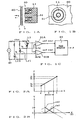
- FIGs. 9A and 9B are a schematic front view and a sectional view, respectively, showing an example where the iron cores (magnetic cores) 45 and 46 in the detecting coils 41 and 42 are oriented in the radial direction of the rotation shaft 22.
- Figs. 11A and 11B the same reference characters as in Figs.
- the arrangement of providing the radial air gap as shown in Figs. 11A and 11B advantageously allows detection of a rotational position to be made without being influenced by mechanical shakes in the thrust direction in the case where the present invention is applied to an environment or machine in which the rotation shaft 22 is apt to shape in the thrust direction. It will be obvious that a modification similar to the one of Figs. 11A and 11B is also possible in other embodiments shown in and after Figs. 12A and 12B.
- stator base 44 allows the detector device to be installed while properly avoiding an obstacle 49, even where there is such an obstacle 49 at a place as shown in Figs. 12A and 12B.
- Such a limited or biased placement of the coils 41 and 42 in the stator section 40 will prove very useful in a situation where the rotary-type position detector device of the present invention is to be installed in a previously-installed machine.
- the rotation shaft 22 i.e. , the object to be detected, itself may be designed to be able to rotate continuously through more than one full rotation or through only a limited angular range less than one full rotation (namely, reciprocatively swing within the limited angular range).
- two coils 41 and 42 are positioned, in spaced apart relation to each other, form an angle of about 45° with respect the rotation shaft 22, and a magnetism-responsive member 21A of the rotor section 20 is designed into a specific shape, such as an oval or near-oval shape, that can bring about progressively increasing/decreasing variations of a two-cycle sine function in the impedance of the coils 41 and 42 per mechanical rotation of the rotation shaft 22.
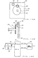
- Figs. 14A to 14C show a position detector device in accordance with another embodiment of the present invention, where the stator section 40 includes only one detecting coil 41 and signals equivalent to two A.C. output signals sin ⁇ sin ⁇ t and cos ⁇ sin ⁇ t are generated on the basis of the output from the only coil 41 and reference voltage Vr.
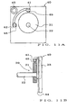
- Fig. 14A is a schematic front view of a principal part of the position detector device, which shows an example of a physical positional relationship between the detecting coil 41 of the stator section 40 and a magnetic-responsive member 21B of the rotor section 20 in the position detector device.
- Fig. 14B is a sectional side view of the part of the rotary-type position detector device shown in Fig. 14A, and Fig.
- FIG. 14C is a block diagram showing an example of electric and electronic circuitry associated with the detecting coil 41 of the stator section 40.
- the magnetic-responsive member 21B of the rotor section 20 is generally in the shape of a swirl cam, which is designed such that the phase component ⁇ in the amplitude functions of the A.C. output signals presents a variation within a range of about 90° relative to a mechanical rotational angle range of the rotation shaft 22. Due to the swirl-cam shape of the rotor section 20, the embodiment of Figs.
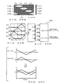
- a between-terminal voltage Vs' of the coil 41 presents a characteristic increasing (or decreasing) linearly in one direction within a predetermined mechanical rotational angle range less than one complete rotation of the rotation shaft 22, as typically illustrated in Fig. 15.
- a value twice as great as a minimum or near-minimum value Vm is set as a reference voltage Vr' and produced by means of the dummy coil 43.
- the output voltages from the coils 41 and 43 are fed to the arithmetic operation circuit 31.
- the amplitude function characteristics of these A.C. output signals within a range W shown in Fig. 15 can be associated equivalently with a single quadrant (90° range) of sine and cosine functions.
- the first A.C. output signal can be associated with the sine function and treated equivalently as sin ⁇ sin ⁇ t
- the second A.C. output signal can be associated with the cosine function and treated equivalently as cos ⁇ sin ⁇ t.
- the range of the phase component ⁇ with respect to the predetermined mechanical rotational angle range W of the rotation shaft 22 is 90°.
- the phase angle ⁇ detected via the phase detection circuit 32 of Fig. 14C will take a value in the range of 0° to 90°, which will indicate, in absolute representation, a rotational position within the predetermined mechanical rotational angle range W of the rotation shaft 22.
- first and second A.C. output signals Va and Vb presenting substantially linear amplitude variation characteristics are associated with the sine and cosine functions sin ⁇ sin ⁇ t and cos ⁇ sin ⁇ t, then their respective amplitude characteristics sin ⁇ and cos ⁇ will present slight non-linearity relative to the predetermined mechanical rotational angle range W of the rotation shaft 22, namely, they will not present real sine and cosine function characteristics.
- the phase detection circuit 32 of Fig. 14C performs its phase detection process while apparently treating the A.C. output signals Va and Vb as signals sin ⁇ sin ⁇ t and cos ⁇ sin ⁇ t having sine and cosine functional amplitude characteristics.
- the detected phase angle ⁇ does not show linearity relative to the rotational angle of the rotation shaft 22 that is the object to be detected here.
- non-linearity between detection output data (indicative of the detected phase angle 8) and actual position to be detected does not matter so much in many cases; namely, it is only necessary that the position detection be performed with predetermined repetitive reproducibility.
- the output data from the phase detection circuit 32 may be converted using an appropriate data conversion table so that accurate linearity can be readily produced between the detection output data and the actual position to be detected. Therefore, the A.C.
- the present invention requires only a primary coil and can eliminate a need for a secondary coil to produce an induced output, so that the present invention can significantly simplify the necessary coil structure and hence can provide a rotary-type position detector device of a greatly simplified structure.
- circuitry for producing the difference in the between-terminal voltages of the coils in each of the coil pairs may be simplified by differentially connecting the coils 41 and 41A and differentially connecting the coils 42 and 42A to provide the respective differences "Vs - Vsa" and "Vc - Vca" without using the specific arithmetic operation circuit 31.
- the magnetism-responsive member 21 is made of a substance of good electrical conductivity, such as copper, the inductance of each of the coils decreases due to an eddy-current loss, and the between-terminal voltage of the coil decreases as the magnetism-responsive member 21 moves closer to the coil. In this case too, the position detecting operations can be performed in the manner as described above. Also note that the magnetism-responsive member 21 may be of a hybrid type comprising a combination of a magnetic substance and an electrically conductive substance. Further, the magnetism-responsive member 21 may comprise a permanent magnet as in the case noted above.
- each of the above-described embodiments may be constructed such that the magnetism-responsive member 21 is fixed while the detecting coils 41 and 42 are provided for movement relative to the magnetism-responsive member 21 in response to displacement of the object to be detected.
- Figs. 17A to 17C show a position detector device in accordance with the other embodiment of the present invention which is designed such that amplitude variations can be produced over a full electric angle range of 0° to 360° in two A.C. output signals of amplitudes presenting sine and cosine function characteristics. More specifically, Fig. 17A is a schematic perspective view of a principal part of the position detector device, which shows an example of a physical positional relationship between a coil section 10 and a magnetism-responsive member 11 in the position detector device. Fig. 17B is a sectional side view of the part of the position detector device taken along the axis of the coil section 10, and Fig . 17C is a block diagram showing an example of electric circuitry associated with the coil section 10.
- the coil section 10 is fixed while the magnetism-responsive member 11 is arranged to move linearly relative to the coil section 10 in response to displacement of the object to be detected.
- the magnetism-responsive member 11 may be fixed while the coil section 10 is arranged to move linearly relative to the magnetism-responsive member 11 in response to displacement of the object to be detected.
- the coil section 10 includes a plurality of coil segments (in the illustrated example, six coil segments L ⁇ , LA, LB, LC, LD and L ⁇ ) disposed in series along a direction in which the object to be detected is displaced, and these coil segments of the coil section 10 are excited by a predetermined single-phase A.C. signal.
- these coil segments L ⁇ , LA, LB, LC, LD and L ⁇ are equal to each other in the number of coil turns, coil length, etc.
- the magnetism-responsive member 11 is formed of a magnetic substance, such as iron, into a shape of a rod or the like, and movable into a space defined by the coil segments of the coil section 10.
- Axial range corresponding to the four intermediate coil segments LA, LB, LC and LD constitutes an effective detecting range of the position detector device. If the axial length of each one of the intermediate coil segments LA, LB, LC and LD is represented by "K", then an axial length four time as great as the length K equals the effective detecting range.
- the coil segments L ⁇ and L ⁇ located immediately before and after the effective detecting range 4K are auxiliary coil segments that are provided in order to more reliably achieve cosine function characteristics; these auxiliary coil segments L ⁇ and L ⁇ may be dispensed with or omitted in a situation where very high detecting accuracy is not required.
- the individual coil segments L ⁇ , LA, LB, LC, LD and L ⁇ are excited, at a constant voltage or current, by a predetermined single-phase A.C. signal ("sin ⁇ t") generated by an A.C. power supply 30.
- Voltages between the respective opposite ends (between-terminal voltages) of these coil segments La, LA, LB, LC, LD and L ⁇ are denoted here by "V ⁇ ", “VA”, “VB”, “VC”, “VD” and “V ⁇ ", respectively, and taps 13 - 19 are provided to take out these voltages V ⁇ , VA, VB, VC, VD and V ⁇ .
- the coil segments L ⁇ , LA, LB, LC, LD and L ⁇ need not necessarily be physically-separated coils, and they may be implemented by just a single continuous coil divided into six coil lengths or portions by the intermediate taps 13 - 19; that is, the coil portion between the taps 13 and 14 functions as the coil segment L ⁇ , the coil portion between the taps 14 and 15 functions as the coil segment LA, the coil portion between the taps 15 and 16 functions as the coil segment LB, the coil portion between the taps 16 and 17 functions as the coil segment LC, the coil portion between the taps 17 and 18 functions as the coil segment LD, and the coil portion between the taps 18 and 19 functions as the coil segment L ⁇ .
- the output voltages V ⁇ , VA, VB, VC, VD and V ⁇ from the individual coil segments are delivered, in predetermined combinations, to analog arithmetic operation circuits 311 and 312, in which they are subjected to an addition and/or subtraction based on predetermined mathematical expressions.
- analog arithmetic operation circuits 311 and 312 produce two A.C. output signals of amplitudes that present sine and cosine function characteristics (i.e., two A.C. output signals having amplitude function characteristics phase-shifted from each other by 90°) corresponding to a current position of the object to be detected.
- the output signal from the analog arithmetic operation circuit 311 is denoted by sin ⁇ sin ⁇ t while the output signal from the other analog arithmetic operation circuit 312 is denoted by and cos ⁇ sin ⁇ t.
- the analog arithmetic operation circuits 311 and 312 comprise operational amplifiers OP1, OP2 and resistor circuits RS1, RS2.
- the present invention is not limited to the foregoing arrangements and the coil segments L ⁇ , LA, LB, LC, LD and L ⁇ may be implemented by separate coils connected in series; in such a case, the separate coils may be excited together by a predetermined single-phase A.C. signal or may be excited parallel via separate exciting circuits in a same phase by a predetermined single-phase A.C. signal.
- the above-described embodiment where a single continuous coil is divided into a plurality of coil segments and the output voltages from these divided coil segments are taken out by intermediate taps is most preferable because it can be simplest in structure.
- the coil segments L ⁇ , LA - LD and L ⁇ will hereinafter be referred to simply as "coils".
- the self-inductance, i.e., impedance, of the coil increases, and thus the voltage between the opposite ends of the coil increases progressively during displacement of the tip 11a of the magnetism-responsive member 11 from one end to the other of that coil.
- a slope in each of the curves, indicative of the output voltage from any one of the coils, represents a region where the tip 11a of the magnetism-responsive member 11 is moving from one end toward the other of the coil in question.
- the progressively-increasing variation curve of the voltage between the opposite ends of the coil which takes place during the movement of the magnetism-responsive member 11 from the coil's one end to the other, can be likened to a functional value variation within a 90° range of the sine or cosine function.
- the analog arithmetic operation circuit 311 can provide an A.C. output signal presenting an amplitude curve of the sine function characteristic as shown in part (B) of Fig. 18, by performing arithmetic operations on the output voltages VA, VB, VC and VD from the coils LA, LB, LC and LD in accordance with Expression (4) below; the A.C. output signal can be represented equivalently by "sin ⁇ sin ⁇ t". (VA - VB) + (VD - VC)
- the other analog arithmetic operation circuit 312 can provide an A.C. output signal presenting an amplitude curve of the cosine function characteristic as shown in part (B) of Fig. 18, by performing arithmetic operations on the output voltages V ⁇ , VA, VB, VC, VD and V ⁇ from the coils L ⁇ , LA, LB, LC, LD and L ⁇ in accordance with Expression (5) below.
- the amplitude curve of the cosine function characteristic as shown in part (B) of Fig. 18 actually presents a minus cosine function characteristic, i.e., "-cos ⁇ sin ⁇ t"
- the amplitude curve corresponds to the cosine function characteristic since it presents a 90° shift relative to the sine function characteristic.
- the A.C. output signal "-cos ⁇ sin ⁇ t" of the minus cosine function characteristic evaluated by Expression (5) may be electrically phase-inverted by 180° to thereby actually generate a signal of "cos ⁇ sin ⁇ t" for use as the A.C. output signal of the cosine function characteristic.
- the A.C. output signal "-cos ⁇ sin ⁇ t" of the minus cosine function characteristic can of course be used just as it is.
- the A.C. output signal "cos ⁇ sin ⁇ t" of the actual cosine function characteristic can be generated by performing the following mathematical expression instead of Expression (5): (VA - V ⁇ ) + (VC - VB) + (VD - V ⁇ )
- phase angle ⁇ in the sine and cosine functions which are amplitude components of the individual A.C. output signals, corresponds to a current position of the object to be detected, and the phase angle ⁇ within a 90° range corresponds to the length K of one of the coils.
- the effective detecting range of the 4K length corresponds to phase angles ⁇ ranging from 0° to 360°. Therefore, every position within the effective detecting range of the 4K length can be detected in an absolute value by detecting such a phase angle ⁇ .
- each of the output voltages would vary to increase or decrease in one direction as depicted by dotted line in contradistinction to a solid-line curve.
- A.C the A.C.
- the variations would appear as positive and negative amplitude variations as shown by dotted lines in contradistinction with solid-line curves in part (B) of Fig. 18.
- the A.C. output signals can be represented as Asin ⁇ sin ⁇ t and Acos ⁇ sin ⁇ t, respectively, and it is this amplitude coefficient A that varies in response to a change in ambient temperature .
- the amplitude coefficient A indicative of the temperature characteristics does not influence the phase angle ⁇ in the sine and cosine functions.
- temperature characteristics can be duly compensated in an automatic fashion, to thereby achieve high-accuracy position detection.
- Every position of the object to be detected can be detected as an absolute value by the phase detection circuit (or amplitude-to-phase converting means) 32 measuring the phase angle ⁇ of the amplitude functions sin ⁇ and cos ⁇ in the A.C. output signals sin ⁇ sin ⁇ t and cos ⁇ sin ⁇ t of the sine and cosine functions.
- the phase detection circuit 32 may be designed in the same manner as noted above.
- the phase detection circuit 32 carries out the phase detection process while regarding these A.C. output signals sin ⁇ sin ⁇ t and cos ⁇ sin ⁇ t as apparently having real sine and cosine function characteristics.
- the detected phase angle ⁇ will not present linearity with respect to the position x of the object to be detected.
- non-linearity between the detection output data (detected phase angle ⁇ ) and the actual position of the object to be detected does not matter very much and can be adjusted whenever necessary, as noted earlier.
- Variation range of the phase angle ⁇ of the amplitude functions sin ⁇ and cos ⁇ in the A.C. output signals sin ⁇ sin ⁇ t and cos ⁇ sin ⁇ t of the sine and cosine functions may be set to be a limited angular range narrower than the full rotational range of 0° to 360° as employed in the above-mentioned embodiment.
- the detectable phase range may be set to be less than the full 360° range particularly where minute or microscopic displacement of the object to be detected is to be detected because the effective detecting range may be narrowed.
- the detectable phase range may also be set to be less than the full 360° range, depending on a purpose of the position detection. Thus, the following paragraphs describe such modifications of the detectable phase range.
- Fig. 19 is a block diagram showing an embodiment of the position detector device, in which phase variations can be produced over a range of 0° to 180°.
- the coil section 10 includes two coils LA and LB corresponding to an effective detecting range of the device and two auxiliary coils L ⁇ and L ⁇ located immediately before and after the coils LA and LB.
- Analog arithmetic operation circuit 313 receives respective between-terminal voltages V ⁇ , VA, VB and V ⁇ output from the coils, so that the operation circuit 313 performs an arithmetic operation as represented by Expression (6) below to thereby generate an A.C.
- the arithmetic operation represented by Expression (6) can generate an A.C. output signal sin ⁇ sin ⁇ t presenting an amplitude curve of a sine function characteristic for the 0°-180° range
- the arithmetic operation represented by Expression (7) can generate an A.C. output signal cos ⁇ sin ⁇ t presenting an amplitude curve of a cosine function characteristic for a range of -90° to 270° (i.e. , from minus 90°, through 0°, plus 90° and 180°, to 270°).
- the auxiliary coil L ⁇ can be omitted as in the above-described cases.
- Every position within the effective detecting range of the 2K length of the two coils LA and LB can be detected in an absolute value by detecting the phase angle ⁇ in the amplitude functions.
- the mathematical expressions employed here may be modified as desired rather than being limited to the above-mentioned alone. Namely, the mathematical expressions can be modified by changing the angular range over which the 180°-wide phase variation should arise. For example, in a situation where an effective phase variation is to take place for an angular range of 180° to 360°, a mathematical expression of "(V ⁇ - VA) + (V ⁇ - VB)" may be used to generate an A.C. output signal sin ⁇ sin ⁇ t of a sine function characteristic, and a mathematical expression of "(VB - VA)" may be used to generate an A.C. output signal cos ⁇ sin ⁇ t of a cosine function characteristic.
- Fig. 20 is a block diagram showing another embodiment of the position detector device, in which phase variations can be produced over a range of 0° to 90°.
- the coil section 10 includes a single coil LA corresponding to an effective detecting range of the device and two auxiliary coils L ⁇ and L ⁇ located immediately before and after the coil LA.
- Analog arithmetic operation circuit 314 receives respective between-terminal voltages V ⁇ , VA and V ⁇ output from the coils, so that the operation circuit 314 performs an arithmetic operation as represented by Expression (8) below to thereby generate an A.C.
- the arithmetic operation represented by Expression (8) can generate an A.C. output signal sin ⁇ sin ⁇ t presenting an amplitude curve of a sine function characteristic for a range of 0°-180° (from 0° through 90° to 180°), and the arithmetic operation represented by Expression (9) can generate an A.C. output signal cos ⁇ sin ⁇ t presenting an amplitude curve of a cosine function characteristic for a range of -90° to 90° (i.e., from minus 90°, through 0° to plus 90°). Therefore, the 0°-90° angular range can be allocated as the effective detecting range of the position detector device.
- the mathematical expressions employed may be modified as desired rather than being limited to the above-mentioned. Namely, the mathematical expressions can be modified by changing the angular range over which the 90° - wide phase variation should arise.
- auxiliary coils L ⁇ and L ⁇ located immediately before and after the effective detecting range
- these auxiliary coils L ⁇ and L ⁇ may be omitted.
- Figs. 21A to 21C shows such a modified embodiment which can produce phase variations within a range of 0° to 180°.
- the coil section 10 includes two coils LA and LB corresponding to the effective detecting range of the position detector device.
- These coils LA and LB are disposed in series along the displacement direction of the object to be detected, so that as the magnetism-responsive member 11 moves relative to the coils LA and LB in response to displacement of the object to be detected, the between-terminal voltages VA and VB of the coils LA and LB vary to increase progressively in sequence as illustrated in Fig. 21B.
- the voltage produced when the magnetism-responsive member 11 has not at all entered the coil is represented by "Vo"
- VN the voltage produced when the magnetism-responsive member 11 has fully entered any one of the coils
- a subtracter circuit 315 performing a subtractive arithmetic operation ("VA - VB") between the between-terminal voltage VA of the coil LA and the between-terminal voltage VB of the coil LB in the example of Fig. 21A, there can be generated an A.C. output signal sin ⁇ sin ⁇ t presenting a sine function characteristic.
- an adder circuit 316 adding together the between-terminal voltages VA and VB of the coils LA and LB and a subtracter circuit 317 performing an operation (“VA + VB - VN - Vo") subtracting the sum of the constant voltages VN and Vo, generated by a constant voltage generator circuit 27, from the sum of the between-terminal voltages VA and VB, there can be generated an A.C.
- the constant voltages VN and Vo generated by the constant voltage generator circuit 27 are caused to vary with temperature characteristics similar to those of the coils LA and LB; for that purpose, it is only necessary that the constant voltage generator circuit 27 be in the form of a dummy coil that has characteristics equal to those of the coil LA or LB and is excited by the same exciting A.C. signal. If a magnetic core similar in characteristics to the magnetism-responsive member 11 is always inserted in such a dummy coil, the same constant voltage as the maximum voltage produced VN produced when the magnetism-responsive member 11 has fully entered any one of the coils can be obtained constantly with temperature characteristics. If no such magnetic core is inserted in the dummy coil, then the same constant voltage as the minimum voltage value Vo can be obtained.
- the above-mentioned constant voltage generator circuit 27 is applicable not only to the case where the number of the coils is two but also to other cases where a smaller or greater number of the coils are employed.
- the A.C. output signal sin ⁇ sin ⁇ t presenting a sine function characteristic can be generated through an arithmetic operation of "VA-VB-VC+Vo" using the output voltages VA, VB and VC and constant voltages VN and Vo from the constant voltage generator circuit 27, and the A.C. output signal cos ⁇ sin ⁇ t presenting a cosine function characteristic can be generated through an arithmetic operation of "VA+VB-VC-VN".
- only one coil may be provided in correspondence with the effective detecting range of the position detector device.
- a phase variation width within the effective detecting range corresponding to the length K of the only coil is less than 90°.
- Figs. 22A to 22C show such an example, where, as shown in Fig. 22A, the only coil LA is connected in series with a resistor R1. With this arrangement, as the amplitude component in the between-terminal voltage VA of the coil LA progressively increases, as shown in Fig. 22B, in response to a movement of the magnetism-responsive member 11, the amplitude component in the between-terminal voltage drop VR of the resistor R1 decreases progressively.
- between-terminal voltage VR of the resistor R1 is regarded as an A.C. output signal sin ⁇ sin ⁇ t of a sine function characteristic and the between-terminal voltage VA of the coil LA is regarded as an A.C. output signal cos ⁇ sin ⁇ t of a cosine function characteristic
- they can be associated with characteristics within a given less-than-90° angular range where the sine and cosine functions cross each other. Therefore, by supplying these A.C. output signals to the phase detection circuit 32, a phase angle ⁇ within the less-than-90° angular range in question can be detected in an absolute value.
- Figs. 23A to 23E show a modification of the embodiment shown in Figs. 22A to 22C, where a dummy coil LN is provided in place of the resistor R1.
- the dummy coil LN is connected in series with the detecting coil LA that would be affected by the movement of the magnetism-responsive member 11, but is not itself affected the movement of the magnetism-responsive member 11.
- the same constant voltage as the maximum voltage produced VN produced when the magnetism-responsive member 11 has fully entered any one the coils can be obtained constantly with temperature characteristics.
- the between-terminal voltages VA and VN of the coil LA and dummy coil LN corresponding to the movement of the magnetism-responsive member 11 are produced in a manner as shown in Fig. 23B.
- Arithmetic operation circuit 318 computes these voltages VA and VN in accordance with predetermined mathematical expressions; for example, the arithmetic operation circuit 318 generates an A.C. output signal sin ⁇ sin ⁇ t of a sine function characteristic through an arithmetic operation of "VA + VN" and generates an A.C. output signal cos ⁇ sin ⁇ t of a cosine function characteristic through an arithmetic operation of "VA - VN".
- Fig. 23D can be associated with characteristics within a given less-than-90° angular range as shown in Fig. 23D. Therefore, by supplying these A.C. output signals to the phase detection circuit 32, a phase angle ⁇ within the less-than-90° angular range in question can be detected in an absolute value.
- the above-mentioned dummy coil LN may be connected with the detecting coil LA in parallel rather than in series as shown in Fig. 23E.
- the example of Fig. 23A can be said to be a modification of the embodiment shown in Figs. 1A - 1C. Because only one reference voltage VN is used, a narrower detectable phase angle range is provided.
- the present invention is not so limited and any desired positional relationship between the coil section 10 and the magnetism-responsive member 11 may be chosen.
- the coils L ⁇ , LA-LD and L ⁇ in the coil section 10 may be disposed such that their axes lie side by side along and the magnetism-responsive member 11 may be arranged to pass near the respective ends of the coils.
- the magnetism-responsive member 11 may be arranged to not move into the inner space defined by the coils, as shown by way of example in Fig. 25A.
- the magnetism-responsive member 11 is arranged to pass near the coils in parallel to their axes.
- an iron core 53 be inserted through an axial inner space defined by the coils L ⁇ , LA-LD and L ⁇ .
- Fig. 25B is a perspective view showing such a modification, where the magnetism-responsive member 11 is in the shape of a hollow cylindrical shape into which the coil section 10 is movable.
- an iron core 53 be inserted through an axial inner space defined by the coils L ⁇ , LA-LD and L ⁇ so that the magnetic flux can flow out to the outer periphery of the coils with increased efficiency.
- Fig. 26 is a schematic sectional side view showing other examples of the coil section 10 and magnetism-responsive member 11.
- the coils L ⁇ , LA-LD and L ⁇ are spaced from each other with a pitch K as in the example of Figs. 17A and 17B, but each of the coils is smaller in length than that in the example of Figs . 17A and 17B.
- every adjoining coils L ⁇ , LA-LD and L ⁇ need not be so close to each other as in the example of Figs. 17A and 17B and may be spaced from each other by any appropriate distance.
- the magnetism-responsive member 11 is tapered, over a length substantially equal to the coil length K, to have a pointed tip 11a.
- the position detector device is also applicable to detection of a position of an object to be detected moving along an arcuate or curved path within a predetermined range, in addition to detection of a position of an object to be detected moving along a completely linear path.
- Fig. 28 shows such an example where the principles of the present invention are applied to the linear position detection case.
- the coil section 10 includes coils LA - LD sequentially disposed arcuately over a predetermined angular range ⁇ , and the magnetism-responsive member 11 is arranged to swing about an axis C over the angular range ⁇ .
- the inventive position detector device can be constructed to detect an angle within a predetermined rotational angular range.
- the magnetism-responsive member 11 may be made of a non-magnetic substance of good electrical conductivity, such as copper or aluminum, rather than a magnetic substance. In such a case, an eddy-current loss will cause the between-terminal voltage of the coil to progressively decrease as the magnetism-responsive member 11 moves closer to the coil.
- the magnetism-responsive member 11 may comprise a permanent magnet and each of the coils in the coil section 10 may include an iron core, as illustratively shown in Fig. 30.
- the permanent magnet 11M functioning as the magnetism-responsive member 11 is in the shape of a ring into which the coil section 10 is movable, and an iron core 54 is inserted through an axial inner space defined by the individual coils L ⁇ , LA-LD and L ⁇ .
- the permanent magnet 11M gets close enough to any one of the coils, a portion of the magnetic core near the coil is magnetically saturated or supersaturated, so that the between-terminal voltage of the coil drops.
- the permanent magnet 11M has a length at least equal to one coil length K in such a manner that the between-terminal voltage of the coil decreases progressively during a movement of the permanent magnet 11M from one end to the other of the coil. Namely, even in the case where the permanent magnet 11M is used as the magnetism-responsive member 11, a progressive decrease can be caused in the between-terminal voltage of the coil during a movement of the permanent magnet 11M from one end to the other of the coil, as in the case where the non-magnetic substance of good electrical conductivity 11b is used. But, in the case of Fig.
- the inventive position detector device may be constructed to provide output amplitude level variations of desired sine and cosine function characteristics by performing appropriate analog arithmetic operations at a succeeding stage.
- the magnetically saturated or super-saturated state may be caused to persist by providing a succession of a plurality of the permanent magnets 11M as the magnetism-responsive member 11.
- the permanent magnet 11M may have any other shape than a ring, such as a rod, in which case the magnetism-responsive member 11 comprising the permanent magnet 11M may be arranged to pass the neighborhood of the coil section 10 in parallel to the axis of thereof. It is preferable that the magnetic core 54 in this modification be formed into a relatively thin shape so that magnetic saturation takes place easily.
- Figs . 31A and 31B show modifications of the placement of the coils in the coil section 10 of Fig. 25B, which is intended to prevent cross-talk between every adjoining coils and thereby enhance the detecting accuracy.
- the coils L ⁇ , LA-LD and L ⁇ are spaced from each other via magnetic spacers 62, so as to prevent spreading of the magnetic flux produced from the individual coils; namely, the magnetic flux from each of the coils follows a path denoted at ⁇ in the figure, along which it flows out from the interior of the coil, then passes a nearest end (i.e., the position of the magnetic spacer 62), outer periphery of the coil and another nearest end (i.e., the position of another magnetic spacer 62), and then returns to the interior of the coil.
- a nearest end i.e., the position of the magnetic spacer 62
- outer periphery of the coil i.e., the position of another magnetic spacer 62
- Such arrangements effectively prevent the undesired cross-talk between the coils, which can greatly improve responsiveness (impedance variations) of the individual coils with respect to the presence of the magnetism-responsive member 11 moving close to the outer periphery of the coils, thereby enhancing the detecting accuracy.
- two magnetic spacers 62 slightly spaced from each other, may be disposed between every adjoining coils as illustrated in Fig. 31B.
- a non-magnetic body may be used as a coil bobbin in place of the magnetic core 53.
- the idea of separating the coils from each other via the magnetic spacers 62a and 62b as in the modifications of Figs. 31A and 31B is also applicable to the embodiment of Fig. 30.
- Fig. 32 is a schematic axial sectional view showing still another embodiment of the position detector device of the present invention, which is arranged such that the coil inductance in the coil section 10 progressively decreases as the magnetism-responsive member 11 moves deeper into the coil section 10.
- Fig. 33A is a schematic perspective view showing a principal part of the detector device, showing an exemplary positional relationship between the coil section 10 and the magnetism-responsive member 11 of Fig. 32.
- Fig. 33B is a schematic sectional view taken along the axis of the coil section 10
- Fig. 33C is a block diagram showing electric circuitry associated with the coil section 10.
- the magnetism-responsive member 11 is in the shape of a hollow cylindrical shape into which the coil section 10 is movable, as in the examples of Figs. 25B and 30.
- the coil section 10 includes a plurality coils --in the illustrated example, four coils LA, LB, LC and LD-- sequentially wound around a bobbin 70, and a non-magnetic and electrically-non-conductive protective tube (which may alternatively be a coating or molding) 71 enclosing and thereby covering the outer periphery of the plurality of coils.
- the protective tube 71 may be formed of any suitable material; however, a heat-shrinkable protective tube made of insulating resin is most preferable because of its low cost.
- the bobbin 70 is in the form of a non-magnetic hollow cylinder, in which is received one or more magnetic rods 72.
- the rods 72 extend throughout the length of the coil section 10 and act to set an inductance value, i.e., impedance, along the entire length of the coil section 10.
- the setting of such an inductance value along the entire length of the coil section 10 can be changed as desired by appropriately adjusting the thickness and the number of the rods 72 received within the bobbin 70.
- each of the magnetic rods 72 is plated with copper or the like to provide a conductive coating on its peripheral surface so that the conductive coating helps to compensate temperature drift characteristics.
- the bobbin 70 may be formed of any suitable metal or resin as long as it is non-magnetic.
- the bobbin 70 be formed of metal, such as non-magnetic stainless steel, to assure a sufficient mechanical strength. In application to small-size equipment or apparatus, however, the bobbin 70 had better be formed of resin because of its lower cost and weight.
- the coils LA, LB, LC and LD which are equal to each other in the number of coil turns, coil length and various other characteristics, are placed in series along the direction in which the object to be detected is caused to move linearly.
- the relative positions between the coil section 10 and the magnetism-responsive member 11 vary in response to displacement of the object to be detected in a similar manner to the embodiment of Figs. 17A and 17B.
- auxiliary coils L ⁇ and L ⁇ may be provided immediately before and after the effective detecting range 4K in a similar manner to the above-described embodiments.
- the one or more magnetic rods 72 extend axially through the individual coils LA, LB, LC and LD at their respective core regions.
- the one or more magnetic rods 72 present a maximum inductance value unless the magnetism-responsive member 11 is located sufficiently close to the coil section 10. As the magnetism-responsive member 11 moves closer to or further into the magnetic field of any one of the coils, the self-inductance of the coil decreases; thus, a voltage between opposite ends of the coil decreases progressively as the tip 11a of the magnetism-responsive member 11 is displaced from one end to the other of the coil in question.
- the substance may be in the form of a just thin layer provided on the magnetism-responsive member 11.
- the magnetism-responsive member 11 may be formed such as by providing an electrically-conductive substance (e.g., copper plating) on and along an inner wall surface of a suitable base member (mobile member) having a hollow cylindrical shape.
- the individual coils LA, LB, LC and LD are excited, at a constant voltage or current, by a predetermined single-phase A.C. signal ("sin ⁇ t") generated by the A.C. power supply 30.
- Voltages between the respective opposite ends of these coils LA, LB, LC and LD are denoted in the figure by "VA”, “VB”, “VC” and “VD", respectively, and taps 14 - 18 are provided to take out these voltages VA, VB, VC and VD.
- the coils LA, LB, LC and LD need not necessarily be physically-separated coils, and they may be replaced by just a single continuous coil divided into four lengths or coil portions by the intermediate taps 14 - 18; that is, the coil portion between the taps 14 and 15 functions as the coil LA, the coil portion between the taps 15 and 16 functions as the coil LB, the coil portion between the taps 16 and 17 functions as the coil LC and the coil portion between the taps 17 and 18 functions as the coil LD.
- Output voltages VA, VB, VC and VD from the individual coils are delivered, in predetermined combinations, to the analog arithmetic operation circuits 311 and 312, in which they are subjected to an addition and/or subtraction based on predetermined mathematical expressions as will be later described.
- these analog arithmetic operation circuits 311 and 312 produce two A.C. output signals sin ⁇ sin ⁇ t and cos ⁇ sin ⁇ t of amplitudes that present sine and cosine function characteristics corresponding to a current position of the object to be detected.
- the self-inductance of the coil decreases, and thus the voltage between the opposite ends of the coil decreases progressively during displacement of the tip 11a of the member 11 from one end to the other of the coil.
- the coils LA, LB, LC and LD are placed in series along the displacement direction of the to-be-detected object, progressive variations in the respective voltages VA, VB, VC and VD of the coils LA, LB, LC and LD will occur sequentially, as illustratively shown in part (A) of Fig.
- a slope in each of the curves, indicative of the output voltages VA, VB, VC and VD from the coils LA, LB, LC and LD, represents a region where the tip 11a of the magnetism-responsive member 11 is moving from one end toward the other of the coil in question.
- a progressive variation curve of the voltage between the opposite ends of the coil which takes place during the movement of the magnetism-responsive member 11 from the coil's one end to the other, can be likened to a functional value variation within a 90° range of the sine or cosine function .
- VA, VB, VC and VD from the individual coils LA, LB, LC and LD and performing an addition and/or subtraction between the combinations, it is possible to produce two A.C. output signals sin ⁇ sin ⁇ t and cos ⁇ sin ⁇ t of amplitudes that present sine and cosine function characteristics corresponding to a current position of the object to be detected.
- the analog arithmetic operation circuit 311 can provide an A.C. output signal indicative of an amplitude curve of the sine function characteristic as shown in part (B) of Fig . 34, by performing arithmetic operations on the output voltages VA, VB, VC and VD from the coils LA, LB, LC and LD in accordance with Expression (10) below; the A.C. output signal can be represented equivalently by "sin ⁇ sin ⁇ t".
- Vo represents a reference voltage corresponding to a minimum inductance value obtained when the magnetism-responsive member 11 has covered the entirety of one of the coils and this reference voltage is used here to offset the output voltage to a zero level.
- the other analog arithmetic operation circuit 312 can provide an A.C. output signal indicative of an amplitude curve of the cosine function characteristic as shown in part (B) of Fig. 34, by performing arithmetic operations on the output voltages VA, VB, VC and VD from the coils LA, LB, LC and LD in accordance with Expression (11) below; the A.C. output signal can be represented equivalently by "cos ⁇ sin ⁇ t".
- Vp represents a reference voltage corresponding to a maximum inductance value obtained when the magnetism-responsive member 11 is not located sufficiently close to any one of the coils and this reference voltage is used here to offset the output voltage VD.
- generation of the reference voltages Vo and Vp had better be carried out using a suitable dummy coil so that these voltages Vo and Vp may be generated with the same temperature drift characteristics as those of the coils LA, LB, LC and LD.
- any other suitable temperature compensation means may of course be employed.
- Phase angle ⁇ in the sine and cosine functions which are amplitude components of the individual A.C. output signals, corresponds to the current position to be detected, and a phase angle ⁇ within the 90° range corresponds to the length of one of the coils .
- the effective detecting range of the 4K length corresponds to phase angles ⁇ ranging from 0° to 360°. Therefore, every position within the effective detecting range of the 4K length can be detected in an absolute value by detecting such a phase angle ⁇ .
- every position within the effective detecting range can be detected in an absolute value by means of the phase detection circuit (or amplitude-to-phase converting means) 32 which detects the phase component ⁇ of the amplitude functions sin ⁇ and cos ⁇ in the A.C. output signals sin ⁇ sin ⁇ t and cos ⁇ sin ⁇ t of the sine and cosine function characteristics.
- each of the output voltages VA, VB, VC and VD would vary to increase or decrease in one direction, relative to a solid-line curve, as depicted by dotted line, as in the case of Fig. 18.
- A.C the A.C.
- the conductive coatings on the magnetic rods 72 act to reduce the inductance of the magnetic circuit due to the eddy-current loss generated therein, the eddy-current loss in the conductive coatings decreases to cause the inductance of the magnetic circuit to increase relatively as the coil impedance increases, for example, in response to a temperature increase, which thus can compensate for the temperature drifts of the coil inductance.
- a similar temperature drift compensation effect can be provided by using a more or less conductive substance as the non-magnetic metal of the bobbin 70.
- each of the embodiments has been described above as generating two A.C. output signals sin ⁇ sin ⁇ t and cos ⁇ sin ⁇ t having amplitude characteristics of sine and cosine functions (so to speak, resolver-type two-phase outputs), the present invention is not so limited and may be designed to generate three or more A.C. output signals having amplitude characteristics of three or more trigonometric functions phase-shifted by a predetermined amount (e.g., sin ⁇ sin ⁇ t, sin( ⁇ -120°) ⁇ sin ⁇ t and sin( ⁇ -240°) ⁇ sin ⁇ t). Further, the number of the coils LA - LD may be greater than four.
- two groups of coils L ⁇ , LA-LD, L ⁇ and L ⁇ ', LA'-LD', L ⁇ ' may be provided in parallel while positionally deviating from each other by a predetermined distance d, in which case the magnetism-responsive member 11 is formed into a size sufficient to cover all the coil groups.
- the coils in all these groups are excited by a same-phase A.C. signal (e.g., sin ⁇ t).
- the deviation of distance b results in an appropriate phase difference less than 90°, and thus a plurality of A.C.
- only one of the analog arithmetic operation circuits 311 of Fig. 17C may be used to generate only one A.C. output signal sin ⁇ sin ⁇ t.
- position detecting data will be obtained from the amplitude voltage level of the only A.C. output signal sin ⁇ sin ⁇ t without using the phase detection circuit 32.
- a position detector device based on the known phase-shift-type phase detection principles can be constructed by combining a pair of the position detector devices capable of generating only one A.C. output signal sin ⁇ sin ⁇ t in the same manner as the above-described modification. Namely, in such a position detector device based on the known phase-shift-type phase detection principles, plural-phase primary coils are excited by two-phase A.C. signals (e.g., sin ⁇ t and cos ⁇ t), and an A.C. output signal (e.g., sin( ⁇ t+ ⁇ )), phase-shifted by a phase angle ⁇ corresponding to a current position of the object to be detected, can be produced as a composite of the output signals of the individual phases.
- A.C. signals e.g., sin ⁇ t and cos ⁇ t
- an A.C. output signal e.g., sin( ⁇ t+ ⁇
- the idea of the present invention may be applied to such a position detector device based on the known phase-shift-type phase detection principles.
- two coil groups may be provided in parallel and the coils in each of the groups may be excited by A.C. signals of different phases (e.g., sin ⁇ t and cos ⁇ t) in such a way that one of the coil groups outputs sin ⁇ cos ⁇ t while the other coil group outputs sin ⁇ sin ⁇ t and an addition or subtraction is performed on these two outputs.
- magnetism-responsive member 11 in each of the embodiments shown in Figs. 17A to 35 may be fixed while the coil section 10 is arranged to move linearly relative to the magnetism-responsive member 11 in response to displacement of the object to be detected.
- magnetism-responsive members 11a, 11b, ... are formed on the rod-shaped base member 66; specifically, each of the magnetism-responsive members 11a, 11b, ... comprises a pattern of a predetermined progressively-increasing or progressively-decreasing shape, which is formed on a surface of the rod-shaped base member 66.
- the patterns of the magnetism-responsive members 11a, 11b, ... differ from each other as appropriate and separate coils L1, L2, ... are provided in corresponding relation to the patterns.
- Various combinations of the substances forming these magnetism-responsive members 11a, 11b, ... and base member 66 may be chosen in the same manner as with the embodiment of Figs. 38A and 38B.
- Fig. 39A is a cross-sectional view showing the rod-shaped base member 66 and coil section 10.
- the coil section 10 is generally in the shape of a ring, in which the rod-shaped base member 66 is inserted for linear movement in the axial direction thereof.
- the first coil L1 is positioned in one half portion of the coil section 10 and the second coil L2 is positioned in the other one half portion of the coil section 10.
- Fig. 39B is a view showing the rod-shaped base member 66 and coil section 10 in an unfolded condition, where arrow x indicates a direction of linear displacement of the object to be detected.
- the magnetism-responsive members 11a and 11b comprise two separate patterns; that is, the first pattern 11a is a triangle progressively increasing or widening in a left-to-right direction while the second pattern 11b is a triangle progressively decreasing or narrowing in the left-to-right direction.
- the first coil L1 covers the positioned area of the pattern 11a.
- the second coil L2 covers the positioned area of the pattern 11b.
- Fig. 39C is a block diagram of electric circuitry associated with the individual coils L1 and L2 of Fig. 39A
- Figs. 39D end 39E are diagrams explanatory of position detecting operation of the embodiment.
- the rod-shaped base member 66 moves in response to displacement of the object to be detected
- the positions of the magnetism-responsive members 11a and 11b corresponding to the coils L1 and L2 change, so that there is produced, in the coils L1 and L2
- self-inductance, i.e., impedance corresponding to areas of the members 11a and 11b corresponding to the coils L1 and L2 and output voltages Va and Vb corresponding to a current position of the object to be detected are produced from the coils L1 and L2.
- Figs. 40A - 40D show the embodiment which can realize a full phase variation from a substantially zero degree to 360 degrees. More specifically, Fig. 40A is a diagram showing, in an unfolded condition, four different patterns 11a, 11b, 11c and 11d that are formed on the base member 66 by the magnetism-responsive member 11. These patterns 11a, 11b, 11c and 11d are positioned in corresponding relation to four regions of a peripheral surface of the rod-shaped base member 66 which are divided circumferentially along the peripheral surface.
- the rod-shaped base member 66 is shown in part (a) of the figure as being divided into four portions along the length thereof, and these divided portions are denoted by P1, P2, P3 and P4, respectively.
- Fig. 40B is a diagram showing progressively-increasing and progressively-decreasing variations in output voltages V1 - V4.
- Fig. 40D is a block diagram of electric circuitry associated with the individual coils L1 - L4, where an analog arithmetic operation circuit 101 performs arithmetic operations of "V1 - V3" and "V2 - V4".
- Fig. 40C is a graph showing an output signal provided as a result of the arithmetic operations.
- the voltage "V1 - V3" obtained by subtracting the output voltage V3 from the voltage V1 can be likened to a sine function characteristic falling within a range from a substantially zero degree to 360 degrees.
- the voltage "V2 - V4" obtained by subtracting the output voltage V4 from the voltage V2 can be likened to a cosine function characteristic falling within a range from a substantially zero degree to 360 degrees. Therefore, there can be generated signals to A.C. output signals (typically, sin ⁇ sin ⁇ t and cos ⁇ sin ⁇ t) having sine and cosine functional characteristics over the substantially 360° range.
- A.C. output signals typically, sin ⁇ sin ⁇ t and cos ⁇ sin ⁇ t
- the base member 66 may be in any other suitable shape than a rod, such as a flat plate, in which case the coils L1, L2, ... are placed in opposed relation to the magnetism-responsive members 11, 11a, 11b, ... formed on the plate.
Landscapes
- Physics & Mathematics (AREA)
- General Physics & Mathematics (AREA)
- Measurement Of Length, Angles, Or The Like Using Electric Or Magnetic Means (AREA)
- Transmission And Conversion Of Sensor Element Output (AREA)
Claims (30)
- Positionsdetektorvorrichtung, die folgendes aufweist:dadurch gekennzeichnet, dass die Impedanz der Spule (L1, L2; 41, 42; LA, LB) in einer solchen Weise geändert wird, dass eine in der Spule (L1, L2; 41, 42; LA, LB) erzeugte Spannung (Vx, Vy; Vs, Vc; Vs'; VA, VB) im Ansprechen auf eine Änderung der Impedanz der Spule (L1, L2; 41, 42; LA, LB) während der Änderung der Relativpositionen innerhalb eines vorgegebenen Bereichs geändert wird, und dass die Positionsdetektorvorrichtung des weiteren folgendes aufweist:einen Spulenabschnitt (50; 40; 10), der mindestens eine Spule (L1, L2; 41, 42; LA, LB) aufweist, die durch ein Wechselstrom- oder Wechselspannungssignal erregbar ist; undein magnetismusempfindliches Teil (60; 61; 62; 63; 64; 21; 21A; 21B; 11; 65; 11A, 11 B), das in bezug auf den Spulenabschnitt (50; 40; 10) bewegbar ist, wobei die Relativpositionen zwischen dem magnetismusempfindlichen Teil (60; 61; 62; 63; 64; 21; 21A; 21B; 11; 65; 11A, 11B) und dem Spulenabschnitt (50; 40; 10) sich im Ansprechen auf eine Verschiebung eines zu detektierenden Objekts ändert und die Impedanz der Spule (L1, L2; 41, 42; LA, LB) im Ansprechen auf die Änderung der Relativpositionen geändert wird,Referenzspannungserzeugungsmittel (Lr1, Lr2; 43; 27; R1; LN) zur Erzeugung mindestens einer vorgegebenen Referenzspannung (Va, Vb; Vr; Vr'; VN; VR) in Form eines Wechselspannungs- oder Wechselstromsignals; undeine an die Spule (L1, L2; 41, 42; LA, LB) und die Referenzspannungserzeugungsmittel (Lr1, Lr2; 43; 27; R1; LN) gekoppelte Schaltung (31A, 31B, 31C, 31D, 31; 315, 316, 317; 318), wobei die Schaltung (31A, 31B, 31C, 31D, 31; 315, 316, 317; 318) zum Empfangen der in der Spule (L1, L2; 41, 42; LA, LB) erzeugten Spannung (Vx, Vy; Vs, Vc; Vs'; VA, VB) und der vorgegebenen Referenzspannung (Va, Vb; Vr; Vr'; VN; VR) ausgelegt ist, wobei mindestens zwei Wechselspannungs- oder Wechselstrom-Ausgangssignale erzeugt werden, die vorgegebene zyklische Amplitudenfunktionen (sin , cos ) als Amplitudenkoeffizienten aufweisen, und die zyklischen Amplitudenfunktionen der beiden Wechselspannungs- oder Wechselstrom-Ausgangssignale sich hinsichtlich der zyklischen Charakteristiken voneinander durch eine vorgegebene Phase unterscheiden.
- Positionsdetektorvorrichtung nach Anspruch 1, bei der die Schaltung (31 A, 31 B, 31 C, 31D, 31; 315, 316, 317; 318) eine arithmetische Operationsschaltung (31A, 31B, 31C, 31D, 31; 315, 316, 317; 318) aufweist, die eine arithmetische Operation zwischen der in der Spule (L1, L2; 41, 42; LA, LB) erzeugten Spannung (Vx, Vy; Vs, Vc; Vs'; VA, VB) und der vorgegebenen Referenzspannung (Va, Vb; Vr; Vr'; VN; VR) durchführt, so dass mindestens zwei Wechselspannungs- oder Wechselstrom-Ausgangssignale erzeugt werden, die vorgegebene zyklische Amplitudenfunktionen (sin , cos ) als Amplitudenkoeffizienten aufweisen.
- Positionsdetektorvorrichtung nach Anspruch 2, bei der der Spulenabschnitt eine einzige Spule (L1) aufweist,
die Referenzspannungserzeugungsmittel erste und zweite Referenzspannungen (Va, Vb) erzeugen, und
die arithmetische Operationsschaltung (31A, 31 B) vorgegebene erste und zweite arithmetische Operationen unter Verwendung einer in der einzigen Spule erzeugten Spannung und der ersten und zweiten Referenzspannungen durchführt, um dadurch ein erstes Wechselspannungs- oder Wechselstrom-Ausgangssignal mit einer ersten Amplitudenfunktion als Amplitudenkoeffizient und ein zweites Wechselspannungs- oder Wechselstrom-Ausgangssignal mit einer zweiten Amplitudenfunktion als Amplitudenkoeffizient zu erzeugen. - Positionsdetektorvorrichtung nach Anspruch 3, bei der die ersten und zweiten Referenzspannungen spezifische Phasenabschnitte in zyklischen Charakteristiken der ersten und zweiten Amplitudenfunktionen der ersten und zweiten Wechselspannungs- oder Wechselstrom-Ausgangssignale definieren, und wobei eine Korrespondenz zwischen den spezifischen Phasenabschnitten und einem Variationsbereich der Relativpositionen durch Ändern der ersten und zweiten Referenzspannungen variiert werden kann.
- Positionsdetektorvorrichtung nach Anspruch 2, bei der der Spulenabschnitt zwei Spulen (L1, L2; 41, 42) aufweist, wobei Positionen der zwei Spulen in bezug auf das magnetismusempfindliche Teil mit entgegengesetzt gerichteten Charakteristiken im Ansprechen auf die Verschiebung des zu detektierenden Objekts gändert werden, worauf eine jeweilige Impedanz der zwei Spulen mit entgegengesetzt gerichteten Charakteristiken variiert.
die Referenzspannungserzeugungsmittel (Lr1) eine einzige Referenzspannung (Va) erzeugen, und
die arithmetische Operationsschaltung (31 C, 31 D) vorgegebene erste und zweite arithmetische Operationen unter Verwendung jeweiliger in den Spulen erzeugten Spannungen und der Referenzspannung durchführt, um dadurch ein erstes Wechselspannungs- oder Wechselstrom-Ausgangssignal mit einer ersten Amplitudenfunktion als Amplitudenkoeffizient und ein zweites Wechselspannungs- oder Wechselstrom-Ausgangssignal mit einer zweiten Amplitudenfunktion als Amplitudenkoeffizient zu erzeugen. - Positionsdetektorvorrichtung nach einem der Ansprüche 1 bis 5, bei der die Referenzspannungserzeugungsmittel mindestens eine Spule einer vorgegebenen Impedanz aufweisen, welche so positioniert ist, dass sie nicht durch eine Bewegung des magnetismusempfindlichen Teils beeinflußt wird.
- Positionsdetektorvorrichtung nach einem der Ansprüche 1 bis 6, bei der die Spule (L1, L2) einen Magnetkern (51, 52) aufweist und das magnetismusempfindliche Teil (60) eine ebene Oberfläche hat, die dem Magnetkern der Spule mit einem dazwischenliegenden Luftspalt gegenüberliegt, und wobei, wenn die ebene Fläche des magnetismusempfindlichen Teils sich im Ansprechen auf eine Positionsänderung des zu detektierenden Objekts bewegt, eine Größenänderung des Luftspalt stattfindet, welche eine Änderung der Impedanz der Spule herbeiführt.
- Positionsdetektorvorrichtung nach einem der Ansprüche 1 bis 6, bei der die Spule einen Magnetkern aufweist und wobei die Impedanz der Spule geändert wird, wenn ein Abstand, der durch einen Luftspalt zwischen dem Magnetkern und dem magnetismusempfindlichen Teil oder einem Bereich des Luftspalts definiert ist, sich im Ansprechen auf eine Positionsänderung des zu detektierenden Objekts ändert.
- Positionsdetektorvorrichtung nach Anspruch 3, bei der die ersten und zweiten Amplitudenfunktionen jeweils Sinus- und Cosinus-Funktionen sind.
- Positionsdetektorvorrichtung nach einem der Ansprüche 1 bis 9, bei der das magnetismusempfindliche Teil mindestens eine magnetische Substanz und/oder eine elektrisch leitende Substanz aufweist.
- Positionsdetektorvorrichtung nach einem der Ansprüche 1 bis 9, bei der das magnetismusempfindliche Teil einen Permanentmagnet aufweist und der Spulenabschnitt einen Magnetkern aufweist.
- Positionsdetektorvorrichtung nach einem der Ansprüche 1 bis 11, bei der die Positionsdetektorvorrichtung eine Dreh-Positionsdetektorvorrichtung ist und das magnetismus empfindliche Teil (21; 21 A; 21 B) drehend bewegbar in bezug auf den Spulenabschnitt ist.
- Positionsdetektorvorrichtung nach Anspruch 12, bei der der Spulenabschnitt zwei Spulen (41, 42) aufweist, die um einen vorgegebenen Winkel voneinander getrennt längs einer Änderungsrichtung der relativen Drehpositionen positioniert sind,
bei der die Referenzspannungserzeugungsmittel (43) eine Referenzspannung (Vr) erzeugen, die einem Variationsmittelpunkt der in jeder der zwei Spulen erzeugten Spannung (Vs, Vc) entspricht, und
bei der die Schaltung (31) eine arithmetische Operation ausführt, um die Referenzspannung von der in einer ersten der zwei Spulen erzeugten Spannung zu subtrahieren, um dadurch ein erstes Wechselspannungs- oder Wechselstrom-Ausgangssignal mit einer ersten zyklischen Amplitudenfunktion als Amplitudenkoeffizient zu erzeugen, wobei die Funktion um den Variationsmittelpunkt in eine positive und negative Richtung schwingt, und die Referenzspannung von der in einer zweiten der zwei Spulen erzeugten Spannung zu subtrahieren, um dadurch ein zweites Wechselspannungs- oder Wechselstrom-Ausgangssignal mit einer zweiten zyklischen Amplitudenfunktion als Amplitudenkoeffizient zu erzeugen, wobei die Funktion um den Variationsmittelpunkt in eine positive und negative Richtung schwingt. - Positionsdetektorvorrichtung nach Anspruch 12, bei der die Schaltung (31) vorgegebene erste und zweite arithmetische Operationen unter Verwendung der in der Spule erzeugten Spannung (Vs') und der Referenzspannung (Vr') durchführt, um dadurch ein erstes Wechselspannungs- oder Wechselstrom-Ausgangssignal mit einer ersten Amplitudenfunktion als Amplitudenkoeffizient und ein zweites Wechselspannungs- oder Wechselstrom-Ausgangssignal mit einer zweiten Amplitudenfunktion als Amplitudenkoeffizient zu erzeugen.
- Positionsdetektorvorrichtung nach Anspruch 12, bei der der Spulenabschnitt in einem vorgegebenen begrenzten Winkelbereich, der kleiner als eine Volldrehung des zu detektierenden Objekts ist, vorgesehen ist.
- Positionsdetektorvorrichtung nach Anspruch 12, bei der jede der Spulen in dem Spulenabschnitt einen Magnetkern aufweist, und die Impedanz von jeder der Spulen geändert wird, wenn ein Abstand, der durch einen Luftspalt zwischen dem Magnetkern und dem magnetismusempfindlichen Teil oder eine Fläche des Luftspalts definiert ist, sich im Ansprechen auf eine Drehpositionsänderung des zu detektierenden Objekts ändert.
- Positionsdetektorvorrichtung nach Anspruch 16, bei der der Magnetkern jeder der Spulen in dem Spulenabschnitt ein Ende aufweist, das in einer Axialrichtung einer Drehwelle ausgerichtet ist, die das zu detektierende Objekt ist, und der Luftspalt zwischen dem Ende des Magnetkerns und des magnetismusempfindlichen Teils im bezug auf die Axialrichtung der Drehwelle definiert ist.
- Positionsdetektorvorrichtung nach Anspruch 16, bei der der Magnetkern jeder der Spulen in dem Spulenabschnitt ein Ende aufweist, das in einer Radialrichtung einer Drehwelle ausgerichtet ist, die das zu detektierende Objekt ist, und der Luftspalt zwischen dem Ende des Magnetkerns und des magnetismusempfindlichen Teils im bezug auf die Radialrichtung der Drehwelle definiert ist, wodurch der Magnetkern gegen mechanisches Schütteln der Drehwelle umempfänglich ist.
- Positionsdetektorvorrichtung, die folgendes aufweist:dadurch gekennzeichnet, dass die Impedanz jedes der Spulensegmente in einer solchen Weise geändert wird, dass eine in mindestens einem der Spulensegmente erzeugte Spannung (Vs, Vsa; Vc, Vca; VA - VD, Vα, Vβ; Va, Vb; V1 - V4)) im Ansprechen auf eine Änderung der Impedanz des mindestens einen der Spulensegmente während der Änderung der Relativpositionen innerhalb eines vorgegebenen Bereichs geändert wird, und dass die Positionsdetektorvorrichtung des weiteren folgendes aufweist:einen Spulenabschnitt (40; 10), der eine Vielzahl von Spulensegmenten (41, 41 A, 42, 42A; LA - LD, Lα, Lβ: L1, L2; L1 - L4) aufweist, die durch ein vorgegebenes Wechselstrom- oder Wechselspannungssignal erregbar sind, wobei die Spulensegmente in einer vorgegebenen Reihenfolge längs einer Verschiebungsrichtung eines zu dektierenden Objekts angeordnet sind; undein magnetismusempfindliches Teil (21; 11; 11 a, 11b), das in bezug auf den Spulenabschnitt (40; 10) beweglich ist, wobei die Relativpositionen zwischen dem magnetismusempfindlichen Teil und dem Spulenabschnitt sich im Ansprechen auf eine Verschiebung eines zu detektierenden Objekts ändern und die Impedanz jedes der Spulensegmente im Ansprechen auf die Änderung der Relativpositionen zwischen dem magnetismusempfindlichen Teil und dem Spulenabschnitt geändert wird,eine an den Spulenabschnitt gekoppelte Schaltung (31; 311, 312; 313; 314; 100; 101), wobei die Schaltung ausgelegt ist, eine Vielzahl von Wechselspannungs- oder Wechselstrom-Ausgangssignalen zu erzeugen, die Amplituden auf der Grundlage von vorgegebenen zyklischen Funktionscharakteristiken (sin , cos ) präsentieren, die einer Position des zu detektierenden Objekts entsprechen, durch Abnehmen von Spannungen an den Spulensegmenten und Durchführen von Addition und/oder Subtraktion der abgenommenen Spannungen.
- Positionsdetektorvorrichtung nach Anspruch 19, bei der der Spulenabschnitt (10) eine Vielzahl von Spulensegmenten (LA - LD, Lα, Lβ) aufweist, die in Serie längs der Verschiebungsrichtung des zu detektierenden Objekts angeordnet sind, und bei der die zyklischen Funktionscharakteristiken (sin , cos ), die die Amplituden einer Vielzahl von Wechselspannungs- oder Wechselstrom-Ausgangssignalen definieren, sich voneinander durch eine vorgegebene Phase unterscheiden.
- Positionsdetektorvorrichtung nach Anspruch 19, bei der die Positionsdetektorvorrichtung eine Dreh-Positionsdetektorvorrichtung ist und das magnetismusempfindliche Teil (21) drehend bewegbar in bezug auf den Spulenabschnitt ist.
- Positionsdetektorvorrichtung nach Anspruch 21, bei der der Spulenabschnitt (40) mindestens zwei Spulensegmentepaare (41, 41 A; 42, 42A) aufweist, wobei die Spulensegmente jedes der Paare um einen Abstand, der einem vorgegebenen Drehwinkel entspricht, voneinander getrennt positioniert sind, und
wobei die relativen Drehpositionen zwischen dem magnetismusempfindlichen Teil (21) und dem Spulenabschnitt (40) im Ansprechen auf die Drehverschiebung des zu detektierenden Objekts variieren und die Impedanz jedes der Spulensegmente im Ansprechen auf eine Variation der relativen Drehpositionen in einer solchen Weise geändert wird, dass die in jedem der Spulensegmente erzeugte Spannung (Vs, Vsa, Vc, Vca) im Ansprechen auf eine Änderung der Impedanz der Spule während der Änderung der relativen Drehpositionen innerhalb eines vorgegebenen Winkelbereichs geändert wird, wobei die in den jeweiligen Spulensegmenten (41, 41 A; 42, 42A) erzeugten Spannungen (Vs, Vsa, Vc, Vca) in jedem der Paare die Differentialcharakteristiken präsentieren, und
bei der die Schaltung (31) für jedes der zwei Spulensegmentepaare (41, 41 A; 42, 42A) ein Wechselspannungs- oder Wechselstrom-Ausgangssignal mit einer der vorgegebenen zyklischen Funktionscharakteristiken (sin , cos ) als Aplitudenkoeffizient durch Abnehmen eines Unterschiedes der in den jeweiligen Spulensegmenten erzeugten Spannungen erzeugt, wobei die zyklischen Funktionscharakteristiken (sin , cos ) der Wechselspannungsoder Wechselstrom-Ausgangssignale, die für zwei Spulensegmentepaare erzeugt werden, in ihren zyklischen Charakteristiken sich durch eine vorgegebene Phase unterscheiden. - Positionsdetektorvorrichtung nach einem der Ansprüche 19 bis 22, bei der die Vielzahl von Wechselspannungs- oder Wechselstrom-Ausgangssignalen ein Wechselspannungs- oder Wechselstrom-Ausgangssignal aufweist, das eine Amplitude auf der Grundlage einer Sinus-Funktionscharakteristik präsentiert, welche der Position des zu detektierenden Objekts entspricht, und ein Wechselspannungs- oder Wechselstrom-Ausgangssignal aufweist, das eine Amplitude auf der Grundlage einer Cosinus-Funktionscharakteristik präsentiert, welche der Position des zu detektierenden Objekts entspricht.
- Positionsdetektorvorrichtung nach einem der Ansprüche 19 bis 23, bei der das magnetismusempfindliche Teil mindestens eine magnetische Substanz und/oder eine elektrisch leitende Substanz aufweist.
- Positionsdetektorvorrichtung nach einem der Ansprüche 19 bis 23, bei der das magnetismusempfindliche Teil einen Permanentmagnet aufweist und der Spulenabschnitt einen Magnetkern aufweist.
- Positionsdetektorvorrichtung nach einem der Ansprüche 19 bis 25, bei der der Spulenabschnitt einen Magnetkern aufweist.
- Positionsdetektorvorrichtung nach Anspruch 19 oder 20, bei der Spulenabschnitt um einen Spulenkörper angeordnet ist und der Spulenkörper einen zylindrischen Abschnitt aufweist, der aus einer nicht-magnetischen Substanz und einem oder mehreren Magnetstäben hergestellt ist, die in dem zylindrischen Abschnitt aufgenommen werden.
- Positionsdetektorvorrichtung nach Anspruch 27, bei der jeder Magnetstab der Spule eine elektrisch leitende Beschichtung hat, die auf seiner Oberfläche ausgebildet ist.
- Positionsdetektorvorrichtung nach Anspruch 19 oder 20, bei der der Spulenabschnitt im wesentlichen eine Spule aufweist, die längs der Verschiebungsrichtung des zu detektierenden Objekts verläuft, und die Vielzahl der Spulensegmente von der einen Spule durch Vorsehen von Ausgangsanschlüssen an vorgegebenen Zwischenpunkten der einen Spule gebildet werden.
- Positionsdetektorvorrichtung nach einem der vorhergehenden Ansprüche, welche außerdem einen Amplituden-Phasen-Konvertierungsabschnitt (32) aufweist, der ausgelegt ist, um die Vielzahl von durch die Schaltung erzeugten Wechselspannungs- oder Wechselstrom-Ausgangssignalen zu empfangen, dann durch eine Korrelation von Amplitudenwerten der Wechselspannungsoder Wechselstrom-Ausgangssignale einen spezifischen Phasenwert in den vorgegebenen zyklischen Funktionen, die die Amplitudenwerte definieren, zu detektieren und anschließend Positionsdetektionsdaten, die für eine Position des zu detektierenden Objekts kennzeichnend sind, zu erzeugen.
Applications Claiming Priority (6)
| Application Number | Priority Date | Filing Date | Title |
|---|---|---|---|
| JP6922999 | 1999-03-15 | ||
| JP6922999 | 1999-03-15 | ||
| JP24975599 | 1999-09-03 | ||
| JP24975599 | 1999-09-03 | ||
| JP35943199 | 1999-12-17 | ||
| JP35943199 | 1999-12-17 |
Publications (2)
| Publication Number | Publication Date |
|---|---|
| EP1037017A1 EP1037017A1 (de) | 2000-09-20 |
| EP1037017B1 true EP1037017B1 (de) | 2003-12-17 |
Family
ID=27299984
Family Applications (1)
| Application Number | Title | Priority Date | Filing Date |
|---|---|---|---|
| EP00105216A Expired - Lifetime EP1037017B1 (de) | 1999-03-15 | 2000-03-13 | Induktiver Stellungsdetektor |
Country Status (3)
| Country | Link |
|---|---|
| US (2) | US6566862B1 (de) |
| EP (1) | EP1037017B1 (de) |
| DE (1) | DE60007202T2 (de) |
Families Citing this family (74)
| Publication number | Priority date | Publication date | Assignee | Title |
|---|---|---|---|---|
| DE60007202T2 (de) * | 1999-03-15 | 2004-11-04 | Goto, Atsutoshi, Fuchu | Induktiver Stellungsdetektor |
| DE10042602A1 (de) | 2000-08-30 | 2002-03-28 | Bosch Gmbh Robert | Verfahren zur Erweiterung des Absolutwinkelmessbereiches bei Magnetfeldsensoren |
| EP1321744A4 (de) * | 2000-09-19 | 2005-09-07 | Honda Motor Co Ltd | Drehpositionsdetektor und mit drehpositionsdetektor ausgestatteter motor |
| EP1248076A1 (de) * | 2001-07-30 | 2002-10-09 | Esec Trading S.A. | Induktiver Sensor für die Positionserfassung eines metallischen Werkstücks |
| EP1283409A1 (de) * | 2001-08-08 | 2003-02-12 | Université de Liège | Detektorvorrichtung |
| WO2003029753A2 (en) * | 2001-10-03 | 2003-04-10 | Measurement Specialties, Inc. | Modular non-contacting position sensor |
| FR2849915B1 (fr) * | 2003-01-10 | 2005-04-22 | Univ Caen Basse Normandie | Dispositif de determination de la forme et/ou de la position d'une surface conductrice, notamment de forme variable dans le temps |
| US7554324B2 (en) * | 2003-10-28 | 2009-06-30 | Honeywell International Inc. | Turbine blade proximity sensor and control system |
| KR100573736B1 (ko) * | 2004-02-16 | 2006-04-25 | 재단법인서울대학교산학협력재단 | 비틀림파를 발생 및 측정할 수 있는 트랜스듀서와 이를이용한 이상진단 장치 및 방법 |
| DE102004041107A1 (de) * | 2004-03-08 | 2005-10-06 | Micro-Epsilon Messtechnik Gmbh & Co Kg | Berührungslos arbeitendes Wegmesssystem |
| US20060001419A1 (en) * | 2004-07-02 | 2006-01-05 | Grand Door Development Limited | Angular sensor and safety mechanism therefor |
| US7124047B2 (en) * | 2004-09-03 | 2006-10-17 | Eaton Corporation | Mathematical model useful for determining and calibrating output of a linear sensor |
| JP4727209B2 (ja) * | 2004-11-08 | 2011-07-20 | Ntn株式会社 | センサ付車輪用軸受 |
| DE102004062278A1 (de) * | 2004-12-23 | 2006-07-13 | Siemens Ag | Messelement und Messverfahren mit einer Spur zur Bestimmung einer Lage |
| US7197424B2 (en) * | 2005-03-31 | 2007-03-27 | Caterpillar Inc | Position sensing system for moveable member |
| DE102005014659A1 (de) * | 2005-03-31 | 2006-10-05 | Robert Bosch Gmbh | Verfahren und Vorrichtung zur berührungslosen Drehwinkelerfassung eines drehbaren Elements |
| DE102005015285A1 (de) * | 2005-04-04 | 2006-10-12 | Knorr-Bremse Systeme für Nutzfahrzeuge GmbH | Niveauregulierungsvorrichtung eines Fahrzeugs |
| JP5094390B2 (ja) * | 2005-06-26 | 2012-12-12 | 株式会社アミテック | 位置センサ |
| FR2891362B1 (fr) * | 2005-09-23 | 2007-11-30 | Billanco | Capteur et procede de mesure de position et de vitesse |
| US7576532B2 (en) * | 2006-04-03 | 2009-08-18 | Scientific Drilling International | Motion transducer for motion related to the direction of the axis of an eddy-current displacement sensor |
| US7456629B2 (en) | 2006-07-11 | 2008-11-25 | Continental Automotive Systems Us, Inc. | Rotary angle sensing system |
| CH698811B1 (de) * | 2006-11-02 | 2009-10-30 | Hsr Hochschule Fuer Technik Ra | Verfahren und Messsystem zum Erfassen und Verarbeiten einer physikalischen Grösse. |
| US7550965B2 (en) * | 2006-11-14 | 2009-06-23 | Raytheon Company | Angular position measurement device |
| DE102006056906A1 (de) * | 2006-12-02 | 2008-06-05 | Continental Teves Ag & Co. Ohg | Sensoranordnung zur Bestimmung eines Absolutwinkels |
| JP4649430B2 (ja) * | 2007-03-20 | 2011-03-09 | セイコーエプソン株式会社 | 非接触電力伝送装置 |
| US9823090B2 (en) | 2014-10-31 | 2017-11-21 | Allegro Microsystems, Llc | Magnetic field sensor for sensing a movement of a target object |
| JP5105201B2 (ja) * | 2008-07-30 | 2012-12-26 | Tdk株式会社 | 角度検出装置、及び角度検出方法 |
| JP5415040B2 (ja) * | 2008-08-01 | 2014-02-12 | 三重電子株式会社 | 自動工具交換装置用モジュール |
| JP5133199B2 (ja) * | 2008-10-28 | 2013-01-30 | 株式会社ミツトヨ | 誘導検出型ロータリーエンコーダ |
| US8269487B2 (en) * | 2008-11-11 | 2012-09-18 | Aisan Kogyo Kabushiki Kaisha | Sheet coil type resolver |
| JP5626962B2 (ja) * | 2010-03-25 | 2014-11-19 | 株式会社ワコム | 位置検出装置および位置入力装置 |
| WO2012008107A1 (ja) * | 2010-07-12 | 2012-01-19 | パナソニック株式会社 | 位相ずれ検出装置、モータ駆動装置、およびブラシレスモータ、並びに位相ずれ検出方法 |
| CN102565754B (zh) * | 2010-11-30 | 2014-02-26 | 华硕电脑股份有限公司 | 可移动装置的定位方法及定位系统 |
| JP2012159495A (ja) * | 2011-01-10 | 2012-08-23 | Aisan Ind Co Ltd | 位置センサ |
| US8947075B2 (en) * | 2011-07-05 | 2015-02-03 | Asmo Co., Ltd. | Variable reluctance type angle sensor |
| US8847720B2 (en) * | 2011-11-04 | 2014-09-30 | Harold J. Goldbaum | Electromagnetic induction device for generation of electrical power |
| US9068815B1 (en) * | 2011-11-09 | 2015-06-30 | Sturman Industries, Inc. | Position sensors and methods |
| JP5752322B2 (ja) * | 2012-04-26 | 2015-07-22 | 三菱電機株式会社 | 磁気式位置検出装置 |
| US9817078B2 (en) | 2012-05-10 | 2017-11-14 | Allegro Microsystems Llc | Methods and apparatus for magnetic sensor having integrated coil |
| US9464881B2 (en) * | 2012-08-01 | 2016-10-11 | Silicon Works Co., Ltd. | Displacement sensor, apparatus for detecting displacement, and method thereof |
| US10856452B1 (en) * | 2013-03-14 | 2020-12-01 | David Fiori, Jr. | Sensor apparatus |
| CZ2013205A3 (cs) * | 2013-03-22 | 2014-10-22 | Rieter Cz S.R.O. | Zařízení pro snímání polohy otáčejícího se pracovního prostředku v aktivním magnetickém ložisku |
| US10145908B2 (en) | 2013-07-19 | 2018-12-04 | Allegro Microsystems, Llc | Method and apparatus for magnetic sensor producing a changing magnetic field |
| US10495699B2 (en) * | 2013-07-19 | 2019-12-03 | Allegro Microsystems, Llc | Methods and apparatus for magnetic sensor having an integrated coil or magnet to detect a non-ferromagnetic target |
| US9425640B2 (en) * | 2013-09-26 | 2016-08-23 | The Charles Stark Draper Laboratory, Inc. | System and method of inductive charging and localization through using multiple primary inductive coils to detect the induced voltage of a secondary inductive coil |
| US10018654B2 (en) * | 2013-11-13 | 2018-07-10 | Semiconductor Components Industries, Llc | Sensor circuit for detecting rotation of an object and method therefor |
| US9733317B2 (en) * | 2014-03-10 | 2017-08-15 | Dmg Mori Seiki Co., Ltd. | Position detecting device |
| DE102014006420A1 (de) * | 2014-05-02 | 2015-11-05 | Diehl Bgt Defence Gmbh & Co. Kg | Winkelsensor |
| US10573453B2 (en) * | 2014-06-19 | 2020-02-25 | Texas Instruments Incorporated | Position sensing using coil sensor |
| US9528857B2 (en) * | 2014-10-17 | 2016-12-27 | Infineon Technologies Ag | Time capture based resolver to digital converter |
| US10712403B2 (en) | 2014-10-31 | 2020-07-14 | Allegro Microsystems, Llc | Magnetic field sensor and electronic circuit that pass amplifier current through a magnetoresistance element |
| US9823092B2 (en) | 2014-10-31 | 2017-11-21 | Allegro Microsystems, Llc | Magnetic field sensor providing a movement detector |
| WO2016140149A1 (ja) * | 2015-03-05 | 2016-09-09 | 日立オートモティブシステムズ株式会社 | 位置検出装置 |
| DE102015220650A1 (de) * | 2015-10-22 | 2017-04-27 | Robert Bosch Gmbh | Drehwinkelsensor |
| US9577185B1 (en) * | 2016-04-28 | 2017-02-21 | Texas Instruments Incorporated | Fluxgate device with low fluxgate noise |
| US10641842B2 (en) | 2017-05-26 | 2020-05-05 | Allegro Microsystems, Llc | Targets for coil actuated position sensors |
| US11428755B2 (en) | 2017-05-26 | 2022-08-30 | Allegro Microsystems, Llc | Coil actuated sensor with sensitivity detection |
| US10996289B2 (en) | 2017-05-26 | 2021-05-04 | Allegro Microsystems, Llc | Coil actuated position sensor with reflected magnetic field |
| US10837943B2 (en) | 2017-05-26 | 2020-11-17 | Allegro Microsystems, Llc | Magnetic field sensor with error calculation |
| WO2019142780A1 (ja) * | 2018-01-16 | 2019-07-25 | 三木 篤子 | 位置検出装置 |
| US10823586B2 (en) | 2018-12-26 | 2020-11-03 | Allegro Microsystems, Llc | Magnetic field sensor having unequally spaced magnetic field sensing elements |
| DE102019213387A1 (de) * | 2019-09-04 | 2021-03-04 | Zf Friedrichshafen Ag | Induktive Verschiebungs- und/oder Positionserfassung |
| US11280637B2 (en) | 2019-11-14 | 2022-03-22 | Allegro Microsystems, Llc | High performance magnetic angle sensor |
| US11237020B2 (en) | 2019-11-14 | 2022-02-01 | Allegro Microsystems, Llc | Magnetic field sensor having two rows of magnetic field sensing elements for measuring an angle of rotation of a magnet |
| US11262422B2 (en) | 2020-05-08 | 2022-03-01 | Allegro Microsystems, Llc | Stray-field-immune coil-activated position sensor |
| US11467003B1 (en) | 2020-06-11 | 2022-10-11 | Blue Origin, Llc | Voltage-current phase-based method for linear and rotary transformer systems, and associated systems and methods |
| US11353337B2 (en) | 2020-11-03 | 2022-06-07 | Semiconductor Components Industries, Llc | Offset cancel systems and methods for resolver-type sensors |
| US11936317B2 (en) | 2021-02-10 | 2024-03-19 | Blue Origin, Llc | Low-voltage fault-tolerant rotating electromechanical actuators, and associated systems and methods |
| US11493361B2 (en) | 2021-02-26 | 2022-11-08 | Allegro Microsystems, Llc | Stray field immune coil-activated sensor |
| US11987395B2 (en) | 2021-06-07 | 2024-05-21 | Blue Origin, Llc | Thrusting rails for launch vehicles, and associated systems and methods |
| US11578997B1 (en) | 2021-08-24 | 2023-02-14 | Allegro Microsystems, Llc | Angle sensor using eddy currents |
| DE102023203231A1 (de) * | 2023-04-06 | 2024-10-10 | Volkswagen Aktiengesellschaft | Positionssensor für ein Ventil und ein Verfahren zur Positionsmessung eines Ventils |
| CN117450903A (zh) * | 2023-10-12 | 2024-01-26 | 精进电动科技股份有限公司 | 一种感应式位置传感器及电磁离合器 |
| US12523717B2 (en) | 2024-02-15 | 2026-01-13 | Allegro Microsystems, Llc | Closed loop magnetic field sensor with current control |
Family Cites Families (11)
| Publication number | Priority date | Publication date | Assignee | Title |
|---|---|---|---|---|
| US4112365A (en) * | 1977-02-15 | 1978-09-05 | Eaton Corporation | Position detecting system |
| US4612503A (en) | 1980-10-21 | 1986-09-16 | Kabushiki Kaisha S G | Rotation speed detection device having a rotation angle detector of inductive type |
| US5109193A (en) * | 1990-06-07 | 1992-04-28 | F.M.E. Corporation | Inductive digital encoder array |
| EP0743508A2 (de) * | 1995-05-16 | 1996-11-20 | Mitutoyo Corporation | Positionssensor unter Anwendung des Strominduktionsprinzips |
| JP4002308B2 (ja) * | 1995-08-10 | 2007-10-31 | 株式会社アミテック | 誘導型回転位置検出装置 |
| US5710509A (en) * | 1995-10-30 | 1998-01-20 | Atsutoshi Goto | Phase difference detection device for an inductive position detector |
| JP3036285U (ja) * | 1996-03-16 | 1997-04-15 | 忠敏 後藤 | シリンダ位置検出装置 |
| US6002250A (en) * | 1996-05-13 | 1999-12-14 | Mitutoyo Corporation | Electronic linear scale using a self-contained, low-power inductive position transducer |
| JP3946827B2 (ja) * | 1996-08-26 | 2007-07-18 | 株式会社アミテック | 近接検出装置 |
| JP3978268B2 (ja) * | 1996-10-13 | 2007-09-19 | 株式会社アミテック | 誘導型位置検出装置 |
| DE60007202T2 (de) * | 1999-03-15 | 2004-11-04 | Goto, Atsutoshi, Fuchu | Induktiver Stellungsdetektor |
-
2000
- 2000-03-13 DE DE60007202T patent/DE60007202T2/de not_active Expired - Lifetime
- 2000-03-13 EP EP00105216A patent/EP1037017B1/de not_active Expired - Lifetime
- 2000-03-14 US US09/525,281 patent/US6566862B1/en not_active Expired - Lifetime
-
2002
- 2002-12-31 US US10/334,384 patent/US6707291B2/en not_active Expired - Lifetime
Also Published As
| Publication number | Publication date |
|---|---|
| EP1037017A1 (de) | 2000-09-20 |
| US6707291B2 (en) | 2004-03-16 |
| DE60007202T2 (de) | 2004-11-04 |
| US20030102862A1 (en) | 2003-06-05 |
| DE60007202D1 (de) | 2004-01-29 |
| US6566862B1 (en) | 2003-05-20 |
Similar Documents
| Publication | Publication Date | Title |
|---|---|---|
| EP1037017B1 (de) | Induktiver Stellungsdetektor | |
| EP0795738B1 (de) | Induktive Linearpositionsgebervorrichtung | |
| US9810550B2 (en) | Position detection device | |
| EP1081390B1 (de) | Hubsensor der selbstinduktiven Art | |
| US7088025B2 (en) | Variable-reluctance resolver and rotational angle sensor using same | |
| JP4390348B2 (ja) | 回転型位置検出装置 | |
| US5708344A (en) | Resolver for detecting rotation position on the basis of response current to pulse voltage | |
| JP5522845B2 (ja) | 回転型位置検出装置 | |
| US6731107B2 (en) | Star-connected sensor | |
| JP2001141409A (ja) | 位置検出装置 | |
| JP2001174206A (ja) | シリンダ位置検出装置 | |
| US5394042A (en) | Angular position homopolar reluctance sensor | |
| JP4336070B2 (ja) | 回転型位置検出装置 | |
| JP4471471B2 (ja) | 相対的回転位置検出装置 | |
| JP2001141410A (ja) | 位置検出装置 | |
| JP2001272204A (ja) | ねじれ量測定装置 | |
| US12613111B2 (en) | Detection device for a position sensor and detection system comprising such a detection device | |
| JP2002107250A (ja) | 圧力計 | |
| JP5135277B2 (ja) | 回転型位置検出装置 | |
| US20230304831A1 (en) | Detection device for a position sensor and detection system comprising such a detection device | |
| JP4612143B2 (ja) | 相対的回転位置検出装置 | |
| JP2005172441A (ja) | 角度および角速度一体型検出装置 | |
| JP2011220851A (ja) | 回転角センサ | |
| JP2002107238A (ja) | 荷重センサ | |
| JPH0989516A (ja) | 位置検出装置用付加装置 |
Legal Events
| Date | Code | Title | Description |
|---|---|---|---|
| PUAI | Public reference made under article 153(3) epc to a published international application that has entered the european phase |
Free format text: ORIGINAL CODE: 0009012 |
|
| 17P | Request for examination filed |
Effective date: 20000313 |
|
| AK | Designated contracting states |
Kind code of ref document: A1 Designated state(s): DE FR GB |
|
| AX | Request for extension of the european patent |
Free format text: AL;LT;LV;MK;RO;SI |
|
| AKX | Designation fees paid |
Free format text: DE FR GB |
|
| 17Q | First examination report despatched |
Effective date: 20021112 |
|
| GRAH | Despatch of communication of intention to grant a patent |
Free format text: ORIGINAL CODE: EPIDOS IGRA |
|
| GRAS | Grant fee paid |
Free format text: ORIGINAL CODE: EPIDOSNIGR3 |
|
| GRAA | (expected) grant |
Free format text: ORIGINAL CODE: 0009210 |
|
| AK | Designated contracting states |
Kind code of ref document: B1 Designated state(s): DE FR GB |
|
| REG | Reference to a national code |
Ref country code: GB Ref legal event code: FG4D |
|
| REF | Corresponds to: |
Ref document number: 60007202 Country of ref document: DE Date of ref document: 20040129 Kind code of ref document: P |
|
| ET | Fr: translation filed | ||
| PLBE | No opposition filed within time limit |
Free format text: ORIGINAL CODE: 0009261 |
|
| STAA | Information on the status of an ep patent application or granted ep patent |
Free format text: STATUS: NO OPPOSITION FILED WITHIN TIME LIMIT |
|
| 26N | No opposition filed |
Effective date: 20040920 |
|
| REG | Reference to a national code |
Ref country code: DE Ref legal event code: R082 Ref document number: 60007202 Country of ref document: DE Representative=s name: KEHL, ASCHERL, LIEBHOFF & ETTMAYR PATENTANWAEL, DE |
|
| REG | Reference to a national code |
Ref country code: DE Ref legal event code: R082 Ref document number: 60007202 Country of ref document: DE Representative=s name: KEHL, ASCHERL, LIEBHOFF & ETTMAYR PATENTANWAEL, DE Effective date: 20140321 Ref country code: DE Ref legal event code: R081 Ref document number: 60007202 Country of ref document: DE Owner name: AMITEQ CO., LTD., JP Free format text: FORMER OWNER: GOTO, ATSUTOSHI, FUCHU, JP Effective date: 20140321 Ref country code: DE Ref legal event code: R081 Ref document number: 60007202 Country of ref document: DE Owner name: AMITEQ CO., LTD., HACHIOJI-SHI, JP Free format text: FORMER OWNER: GOTO, ATSUTOSHI, FUCHU, TOKIO/TOKYO, JP Effective date: 20140321 Ref country code: DE Ref legal event code: R082 Ref document number: 60007202 Country of ref document: DE Representative=s name: KEHL, ASCHERL, LIEBHOFF & ETTMAYR - PATENTANWA, DE Effective date: 20140321 |
|
| REG | Reference to a national code |
Ref country code: FR Ref legal event code: TP Owner name: AMITEQ CO., LTD., JP Effective date: 20140416 |
|
| REG | Reference to a national code |
Ref country code: GB Ref legal event code: 732E Free format text: REGISTERED BETWEEN 20140501 AND 20140507 |
|
| REG | Reference to a national code |
Ref country code: FR Ref legal event code: PLFP Year of fee payment: 17 |
|
| REG | Reference to a national code |
Ref country code: FR Ref legal event code: PLFP Year of fee payment: 18 |
|
| REG | Reference to a national code |
Ref country code: FR Ref legal event code: PLFP Year of fee payment: 19 |
|
| PGFP | Annual fee paid to national office [announced via postgrant information from national office to epo] |
Ref country code: GB Payment date: 20190325 Year of fee payment: 20 Ref country code: FR Payment date: 20190326 Year of fee payment: 20 |
|
| PGFP | Annual fee paid to national office [announced via postgrant information from national office to epo] |
Ref country code: DE Payment date: 20190523 Year of fee payment: 20 |
|
| REG | Reference to a national code |
Ref country code: DE Ref legal event code: R071 Ref document number: 60007202 Country of ref document: DE |
|
| REG | Reference to a national code |
Ref country code: GB Ref legal event code: PE20 Expiry date: 20200312 |
|
| PG25 | Lapsed in a contracting state [announced via postgrant information from national office to epo] |
Ref country code: GB Free format text: LAPSE BECAUSE OF EXPIRATION OF PROTECTION Effective date: 20200312 |