EP1037069A2 - Télémètre - Google Patents
Télémètre Download PDFInfo
- Publication number
- EP1037069A2 EP1037069A2 EP00105549A EP00105549A EP1037069A2 EP 1037069 A2 EP1037069 A2 EP 1037069A2 EP 00105549 A EP00105549 A EP 00105549A EP 00105549 A EP00105549 A EP 00105549A EP 1037069 A2 EP1037069 A2 EP 1037069A2
- Authority
- EP
- European Patent Office
- Prior art keywords
- light
- camera
- intensity
- image
- rangefinder
- Prior art date
- Legal status (The legal status is an assumption and is not a legal conclusion. Google has not performed a legal analysis and makes no representation as to the accuracy of the status listed.)
- Withdrawn
Links
Images











Classifications
-
- G—PHYSICS
- G01—MEASURING; TESTING
- G01S—RADIO DIRECTION-FINDING; RADIO NAVIGATION; DETERMINING DISTANCE OR VELOCITY BY USE OF RADIO WAVES; LOCATING OR PRESENCE-DETECTING BY USE OF THE REFLECTION OR RERADIATION OF RADIO WAVES; ANALOGOUS ARRANGEMENTS USING OTHER WAVES
- G01S17/00—Systems using the reflection or reradiation of electromagnetic waves other than radio waves, e.g. lidar systems
- G01S17/88—Lidar systems specially adapted for specific applications
- G01S17/89—Lidar systems specially adapted for specific applications for mapping or imaging
-
- G—PHYSICS
- G06—COMPUTING OR CALCULATING; COUNTING
- G06Q—INFORMATION AND COMMUNICATION TECHNOLOGY [ICT] SPECIALLY ADAPTED FOR ADMINISTRATIVE, COMMERCIAL, FINANCIAL, MANAGERIAL OR SUPERVISORY PURPOSES; SYSTEMS OR METHODS SPECIALLY ADAPTED FOR ADMINISTRATIVE, COMMERCIAL, FINANCIAL, MANAGERIAL OR SUPERVISORY PURPOSES, NOT OTHERWISE PROVIDED FOR
- G06Q50/00—Information and communication technology [ICT] specially adapted for implementation of business processes of specific business sectors, e.g. utilities or tourism
- G06Q50/10—Services
- G06Q50/20—Education
-
- G—PHYSICS
- G01—MEASURING; TESTING
- G01S—RADIO DIRECTION-FINDING; RADIO NAVIGATION; DETERMINING DISTANCE OR VELOCITY BY USE OF RADIO WAVES; LOCATING OR PRESENCE-DETECTING BY USE OF THE REFLECTION OR RERADIATION OF RADIO WAVES; ANALOGOUS ARRANGEMENTS USING OTHER WAVES
- G01S17/00—Systems using the reflection or reradiation of electromagnetic waves other than radio waves, e.g. lidar systems
- G01S17/02—Systems using the reflection of electromagnetic waves other than radio waves
- G01S17/06—Systems determining position data of a target
- G01S17/08—Systems determining position data of a target for measuring distance only
-
- G—PHYSICS
- G01—MEASURING; TESTING
- G01S—RADIO DIRECTION-FINDING; RADIO NAVIGATION; DETERMINING DISTANCE OR VELOCITY BY USE OF RADIO WAVES; LOCATING OR PRESENCE-DETECTING BY USE OF THE REFLECTION OR RERADIATION OF RADIO WAVES; ANALOGOUS ARRANGEMENTS USING OTHER WAVES
- G01S17/00—Systems using the reflection or reradiation of electromagnetic waves other than radio waves, e.g. lidar systems
- G01S17/02—Systems using the reflection of electromagnetic waves other than radio waves
- G01S17/06—Systems determining position data of a target
- G01S17/42—Simultaneous measurement of distance and other co-ordinates
-
- G—PHYSICS
- G01—MEASURING; TESTING
- G01S—RADIO DIRECTION-FINDING; RADIO NAVIGATION; DETERMINING DISTANCE OR VELOCITY BY USE OF RADIO WAVES; LOCATING OR PRESENCE-DETECTING BY USE OF THE REFLECTION OR RERADIATION OF RADIO WAVES; ANALOGOUS ARRANGEMENTS USING OTHER WAVES
- G01S7/00—Details of systems according to groups G01S13/00, G01S15/00, G01S17/00
- G01S7/48—Details of systems according to groups G01S13/00, G01S15/00, G01S17/00 of systems according to group G01S17/00
- G01S7/481—Constructional features, e.g. arrangements of optical elements
-
- G—PHYSICS
- G01—MEASURING; TESTING
- G01S—RADIO DIRECTION-FINDING; RADIO NAVIGATION; DETERMINING DISTANCE OR VELOCITY BY USE OF RADIO WAVES; LOCATING OR PRESENCE-DETECTING BY USE OF THE REFLECTION OR RERADIATION OF RADIO WAVES; ANALOGOUS ARRANGEMENTS USING OTHER WAVES
- G01S7/00—Details of systems according to groups G01S13/00, G01S15/00, G01S17/00
- G01S7/48—Details of systems according to groups G01S13/00, G01S15/00, G01S17/00 of systems according to group G01S17/00
- G01S7/497—Means for monitoring or calibrating
-
- G—PHYSICS
- G09—EDUCATION; CRYPTOGRAPHY; DISPLAY; ADVERTISING; SEALS
- G09B—EDUCATIONAL OR DEMONSTRATION APPLIANCES; APPLIANCES FOR TEACHING, OR COMMUNICATING WITH, THE BLIND, DEAF OR MUTE; MODELS; PLANETARIA; GLOBES; MAPS; DIAGRAMS
- G09B19/00—Teaching not covered by other main groups of this subclass
- G09B19/06—Foreign languages
-
- G—PHYSICS
- G09—EDUCATION; CRYPTOGRAPHY; DISPLAY; ADVERTISING; SEALS
- G09B—EDUCATIONAL OR DEMONSTRATION APPLIANCES; APPLIANCES FOR TEACHING, OR COMMUNICATING WITH, THE BLIND, DEAF OR MUTE; MODELS; PLANETARIA; GLOBES; MAPS; DIAGRAMS
- G09B5/00—Electrically-operated educational appliances
- G09B5/06—Electrically-operated educational appliances with both visual and audible presentation of the material to be studied
Definitions
- the present invention relates to a rangefinder for measuring the three-dimensional (3D) shape or obtaining range information of an object.
- Figure 24 illustrates an exemplary configuration for a prior art rangefinder.
- the rangefinder shown in Figure 24 captures a set of images of an object by projecting light on-to the object, thereby measuring the 3D shape of the object based on the principle of triangulation.
- the rangefinder shown in Figure 24 was designed to operate in real time.
- the rangefinder includes laser light sources 101A and 101B , half mirror 102 , light source controller 103 , rotating mirror 104 , rotation controller 105 , lens 107 , wavelength separating filters 108A and 108B , CCD's 109A , 109B , 109C , signal processors 110A , 110B , 111 , distance calculator 112 and controller 113 .
- the wavelengths of laser beams emitted from the light sources 101A and 101B are slightly different from each other.
- the laser beams outgoing from the light sources 101A and 101B are combined with each other at the half mirror 102.
- the intensities of the beams emitted from the light sources 101A and 101B are controlled by the light source controller 103.
- the rotating mirror 104 is provided to scan the combined laser radiation and the rotation thereof is controlled by the rotation controller 105 .
- the laser radiation which has been projected onto an object 106 and reflected therefrom, is condensed by the lens 107 , selectively passed through the wavelength separating filters 108A and 108B and then incident on the CCD's 109A , 109B and 109C.
- the filters 108A and 108B separate parts of the reflected radiation with the same wavelengths as those of the light sources 101A and 101B , respectively.
- the CCD's 109A and 109B capture monochromatic images of the object 106
- the other CCD 109C captures a color image of the object 106 .
- the signal processors 110A , 110B and 111 are provided for these CCD's 109A , 109B and 109C , respectively.
- the distance calculator 112 obtains, by computation, information about the distance or shape of the object 106 based on the intensities of the beams incident on the CCD's 109A and 109B .
- the controller 113 synchronizes or controls the overall operating timing of this rangefinder.
- the laser light sources 101A and 101B emit laser beams with slightly different wavelengths. These laser beams are in the shape of a slit with an optical cross section crossing the scanning direction of the rotating mirror 104 at right angles. That is to say, if the rotating mirror 104 scans the laser beams horizontally, then the slitlike beams extend vertically.
- Figure 25 illustrates how the intensities of the laser beams projected from these two light sources 101A and 101B change with wavelength.
- the beams emitted from these light sources 101A and 101B have close wavelengths. This is because the reflectance of the object 106 is less dependent on the wavelength in such a case.
- the laser beams emitted from the laser light sources 101A and 101B are combined into a single beam at the half mirror 102 . Then, the combined beam is scanned at the rotating mirror 104 toward the object 106 .
- the rotation controller 105 drives the rotating mirror 104 on a field-by-field basis, thereby scanning the laser beams that have been projected from the light sources 101A and 101B .
- the light source controller 103 changes the intensities of the beams emitted from these light sources 101A and 101B as shown in Figure 26(a) within the cycle time of one field. That is to say, the intensities of the laser beams are changed while the rotating mirror is driven.
- the laser radiation that has been reflected from the object 106 is condensed by the lens 107 toward the CCD's 109A , 109B and 109C .
- the wavelength separating filter 108A selectively transmits only a part of the laser radiation with the same wavelength as that of the beam emitted from the light source 101A but reflects the remaining parts of the radiation with other wavelengths.
- the wavelength separating filter 108B selectively transmits only a part of the laser radiation with the same wavelength as that of the beam emitted from the light source 101B but reflects the remaining parts of the radiation with other wavelengths.
- the signal processors 110A and 110B perform signal processing on the outputs of the CCD's 109A and 109B as is done for an ordinary monochromatic camera.
- the signal processor 111 performs signal processing on the output of the CCD 109C as is done for an ordinary color camera.
- the distance calculator 112 obtains distances for respective pixels based on the outputs of the CCD's 109A and 109B , the baseline length and the coordinates of the pixels.
- the distance calculator 112 calculates an intensity ratio of the reflected parts of the laser radiation.
- the relationship between the intensity ratio and the scanning time is known. Accordingly, if an intensity ratio is given, then a specific point in time during one scan period can be estimated automatically. And the angle ⁇ of rotation of the rotating mirror 104 can be derived from the specific point in time. For example, as shown in Figure 26(b) , supposing the intensity ratio is Iao/Ibo, then the scanning time is estimated to be t0, from which the angle ⁇ of rotation of the rotating mirror 104 is known. This angle ⁇ corresponds to the angle formed by a visual axis, which extends from the light source to the object, with the X-axis.
- a characteristic table representing the relationship between the intensity ratio Ia/Ib and the angle ⁇ of rotation may be prepared by substituting the angle ⁇ of rotation for the axis of abscissas of the graph shown in Figure 26(b) .
- the angle ⁇ of rotation can be derived directly from the given intensity ratio without using the scanning time t .
- Figure 27 diagrammatically illustrates how the distance calculator 112 derives the distance.
- O is the center of the lens 107
- P is a point of incidence on the object 106
- Q is a point at which the axis of rotation of the rotating mirror 104 is located.
- the CCD 109 is illustrated as being located closer to the object 106 .
- the distance between the CCD 109 and the center O of the lens 107 is identified by f .
- the angle formed by a visual axis QP with the X-axis within the XZ plane is ⁇
- the angle formed by another visual axis OP with the X-axis within the XZ plane is ⁇
- the angle formed by still another visual axis OP with the Z-axis within the YZ plane is ⁇
- Y L ⁇ tan ⁇ ⁇ tan ⁇ ⁇ tan ⁇ /(tan ⁇ +tan ⁇ )
- Z L ⁇ tan ⁇ ⁇ tan ⁇ /(tan ⁇ +tan ⁇ )
- the angle ⁇ can be derived from the intensity ratio of the reflected beams that are being monitored by the CCD's 109A and 109B as described above.
- the rangefinder of this type includes no sweep means such as laser light sources or rotating mirrors. Instead, the rangefinder includes a light source section that can project multiple beams with mutually different two-dimensional (2D) radiation patterns.
- this alternative rangefinder projects multiple beams with different 2D radiation patterns onto an object on a timing-sharing basis, makes cameras capture the images of the object as represented by the reflected beams thereof and estimates the distance of the object based on the intensities of the reflected beams.
- the rangefinder estimates the distance by deriving three-dimensional information about the object based on the coordinates of the images and in accordance with the relationship between the intensity ratio or the intensities of the reflected beams and the angles of projection of beams irradiated.
- the rangefinder of this type can perform three-dimensional measurement much more stably and reliably, because the entire measurement process is implemented by electronic operations. In addition, since this rangefinder needs no mechanical operations, the cost thereof is relatively low.
- the prior art rangefinder has the following drawbacks.
- the rangefinder including the light source section for projecting multiple beams with mutually different 2D radiation patterns ordinarily uses xenon flash lamps as its light sources.
- the intensity of a beam emitted from such a flash lamp is variable by about ⁇ 5% or less every time the beam is emitted. Accordingly, even when the same object is imaged, the intensity of a beam reflected therefrom or the intensity ratio is changeable. In addition, variation is also found among individual flash lamps. Thus, the distance of the object cannot be estimated accurately without taking those variations into account.
- each of the beams emitted from the light sources is vertically magnified by a lens system, transformed into a slitlike beam and then made to sweep the object using a rotating mirror.
- a rangefinder estimates the distance of the object while assuming the intensity of the projected beam is variable only horizontally but is constant vertically.
- the intensity of the slitlike beam is non-uniform due to the effects of lens shading. Specifically, since the intensity of the beam locally attenuates when passing through the lens system, the intensity at the edges of the slit is weaker than the intensity at the center of the slit.
- an inventive rangefinder includes: a light source for projecting light onto an object such that an intensity of the projected light varies on the object at least from place to place; a camera for capturing an image of the object by using part of the projected light, which part has been reflected from the object; and a 3D information generator for generating 3D information of the object from the reflected light image captured by the camera.
- the 3D information generator includes a light intensity corrector. The corrector corrects an intensity of the reflected light image according to correction information representing an intensity of the projected light, and generates the 3D information using an image that has been corrected by the light intensity corrector.
- the intensity of the reflected light image captured by the camera is corrected by the light intensity corrector according to the correction information representing the intensity of the projected light.
- the 3D information generator generates the 3D information using an image that has been corrected by the light intensity corrector.
- the light source may project multiple light beams with mutually different projection patterns.
- the light intensity corrector may correct respective intensities of reflected light images corresponding to the projected beams.
- the 3D information generator may generate the 3D information based on a ratio of intensities of the reflected light images that have been corrected by the light intensity corrector.
- the rangefinder may further include a light receiver for detecting an intensity of the light that has been projected from the light source and outputting the intensity as the correction information.
- the light intensity corrector may use, as the correction information, brightness in a predetermined part of the image captured by the camera.
- the light intensity corrector may perform offset processing on the reflected light image by subtracting black level components from image data and then make the correction.
- Another inventive rangefinder includes: a light source for projecting light onto an object such that a characteristic of the projected light varies depending on a direction in which the light has been projected; a camera for capturing an image of the object by using part of the projected light, which part has been reflected from the object; and a 3D information generator for generating 3D information of the object from the reflected light image captured by the camera.
- the 3D information generator includes multiple lookup tables, each describing a correspondence between the characteristic of the reflected light and the direction in which the light has been projected, selects at least one of the lookup tables for each pixel location in the image captured by the camera and generates the 3D information by reference to the lookup table(s) selected.
- the 3D information generator includes multiple lookup tables, each describing a correspondence between the characteristic of the reflected light and the direction in which the light has been projected, and selects one of the tables for each pixel location in the image captured by the camera.
- the 3D information generator includes multiple lookup tables, each describing a correspondence between the characteristic of the reflected light and the direction in which the light has been projected, and selects one of the tables for each pixel location in the image captured by the camera.
- the lookup tables may be provided for at least some epipolar lines in the image captured by the camera. On each and every epipolar line, one-to-one correspondence is always met between the optical characteristic of the reflected light and the direction in which the light has been projected. Thus, it would be more efficient and cost effective if the lookup tables are provided for the respective epipolar lines. As a result, highly accurate 3D information can be generated with reasonable computational cost and storage capacity consumed.
- the 3D information generator may newly make a lookup table for pixels on one of the epipolar lines that is associated with none of the lookup tables by performing interpolation on at least two of the existent lookup tables associated with corresponding ones of the epipolar lines near the epipolar line on target.
- the light source and the camera may be placed such that a line connecting the light source and the camera together matches an X-axis of a world coordinate system and is parallel to an x-axis of a camera coordinate system.
- the epipolar lines are parallel to the x-axis in the image captured by the camera.
- Figure 1 illustrates an arrangement of a rangefinder according to a first embodiment of the present invention.
- a light source section 2 includes two flash lamps 2a and 2b for projecting light onto an object 106 such that the intensity of the projected light varies on the object 106 from place to place.
- a camera 1 receives part of the light that has been projected from the light source section 2 and then reflected from the object 106 .
- a light source controller 5 gets each of the light sources 2a and 2b alternately flashed once a frame or field.
- a distance calculator 6 which is equivalent to the 3D information generator as defined in the appended claims, generates a range image representing the 3D information of the object 106 from an image that has been captured by the camera 1 by using the reflected light. In this specification, such an image will be called a "reflected light image”.
- light receivers 21a and 21b are provided for the light sources 2a and 2b in the light source section 2 to detect the intensities of the light beams emitted from the light sources 2a and 2b , respectively.
- the light intensities that have been detected by the light receivers 21a and 21b are provided to the light source controller 5 , which in turn sends these values as predetermined correction information to the distance calculator 6 .
- the distance calculator 6 corrects the reflected light image and generates the range image from the corrected image.
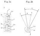
- Figure 2(a) is a perspective view illustrating exemplary configurations for the light sources 2a and 2b .
- flash lamps 7 and 8 such as xenon lamps are vertically stacked such that the axes thereof are aligned with each other.
- Reflectors 9 and 10 are placed behind these lamps 7 and 8 , respectively, such that the range of the light reflected from one of these reflectors 9 and 10 shifts from that of the light reflected from the other by a predetermined angle around the axis.
- the light receivers 21a and 21b are herein implemented as photodiodes provided for the reflectors 9 and 10 , respectively, to detect the intensities of the light beams emitted from these light sources 2a and 2b .
- Figure 2(b) is a plan view of the light sources 2a and 2b shown in Figure 2(a) .
- the light sources 2a and 2b radiate, or project, the light beams within the ranges A and B , respectively.
- the xenon lamps preferably have small emissive portions such that these lamps can be regarded as point light sources in the plan view.
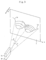
- Figure 3 schematically illustrates exemplary light patterns that have been radiated from the light sources 2a and 2b shown in Figure 2 .
- the solid lines La and Lb represent the brightness on a virtual screen Y , on which the light beams have been projected from the light sources 2a and 2b .
- the higher the solid lines La and Lb in the direction indicated by the arrow in Figure 3 the brighter the light.
- the light projected from each of these light sources 2a and 2b is intensest, or brightest, on the center axis of the projection range and gradually becomes weaker, or darker, toward the peripheral regions of the range.
- Such a distribution results from the disposition of the semi-cylindrical reflectors 9 and 10 behind the flash lamps 7 and 8 , respectively. And depending on which directions these reflectors 9 and 10 face, the light beams projected from the light sources 2a and 2b may or may not partially overlap with each other.
- Figure 4 is a graph illustrating a relationship between a horizontal position on the virtual screen Y (i.e., in the direction H shown in Figure 3 ) and the light intensity.
- a range ⁇ of the light pattern projected from one of the light sources 2a and 2b through the space of the object has relatively bright and relatively dark parts on right- and left-hand sides of the light source 2a or 2b , respectively.
- the range ⁇ of the light pattern projected from the other light source 2b or 2a through the space of the object has relatively dark and relatively bright parts on right- and left-hand sides of the light source 2b or 2a , respectively.
- the light intensities of the light sources 2a and 2b in the range ⁇ will be represented as Ia and Ib, respectively.
- the distributions of light intensities shown in Figure 4 are about a plane passing through the center of the lens of the camera 1 and corresponding to a predetermined y coordinate (e.g., 0). Actually, the distributions differ depending on the y coordinate.
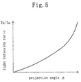
- Figure 5 is a graph illustrating a relationship between the projection angle ⁇ of the light outgoing from the light source section 2 and a light intensity ratio Ib/Ia in the range ⁇ shown in Figure 4 . As shown in Figure 5 , there is a substantially linear relationship between the light intensity ratio Ib/Ia and the projection angle ⁇ of the light in the range ⁇ .
- two types of light patterns should be projected in advance onto a plane standing vertically and the light beams that have been reflected from the plane should be received by the camera 1 .
- the relationship between the light intensity ratio and the projection angle of the light such as that shown in Figure 5 should be obtained in advance for each y coordinate.
- the light source section 2 should be disposed such that a line connecting the center of the lens of the camera 1 to the light source section 2 is parallel to the x-axis of the image plane. In such a case, the distance of the object can be estimated accurately based on the data representing the relationships between the light intensity ratios and projection angles of the light associated with respective y coordinates.
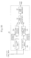
- Figure 6 illustrates an exemplary internal configuration for the distance calculator 6 .
- the distance calculator 6 includes first and second image memories 61a and 61b , first and second light intensity correctors 62a and 62b , a light intensity ratio calculator 63 and a range image generator 64 .
- Image signals representing the reflected light images captured by the camera 1 are temporarily stored on the first and second image memories 61a and 61b on a frame-by-frame basis.
- the first and second light intensity correctors 62a and 62b correct the light intensities represented by the image signals stored on the first and second image memories 61a and 61b , respectively, according to the correction information.
- the light intensity ratio calculator 63 calculates the ratio of the light intensities that have been corrected by the first and second light intensity correctors 62a and 62b . And based on the light intensity ratio obtained, the range image generator 64 generates a range image of the object 106 .
- An image signal representing a reflected part of the light projected from the light source 2a is stored on the first image memory 61a .
- an image signal representing a reflected part of the light projected from the light source 2b is stored on the second image memory 61a .
- the light intensity detected by the light receiver 21a is provided as correction information Isa to the first light intensity corrector 62a
- the light intensity detected by the light receiver 21b is provided as correction information Isb to the second light intensity corrector 62b .
- reference values Ira and Irb used for correcting the light intensities are stored in advance on the first and second light intensity correctors 62a and 62b , respectively.
- Each of the reference values Ira and Irb may be an average of intensities that have been actually measured several times by the light receiver 21a or 21b for the light beam projected from the light sources 2a or 2b .
- the rangefinder estimates the distance of the object.
- the depth Z i.e., Z coordinate
- the distance calculator 6 corrects the light intensity.
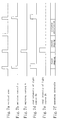
- Figure 7 is a timing diagram illustrating how the rangefinder operates in accordance with this embodiment.
- the light source controller 5 in response to the vertical sync signal (shown in portion (a) of Figure 7 ) provided from the camera 1 , the light source controller 5 alternately outputs emission control signal a or b (shown in portions (b) and (c) of Figure 7 ) at regular intervals (e.g., once a frame or field), thereby getting the light sources 2a and 2b flashed one after the other.
- the light receivers 21a and 21b detect the intensities of the light beams emitted from the light sources 2a and 2b by turns. And the light intensities detected by the light receivers 21a and 21b are supplied to the light source controller 5 at respective times shown in portions (d) and (e) of Figure 7 .
- the camera 1 captures the reflected light images on a time-sharing basis. Specifically, the camera 1 captures a reflected light image resulting from the light projected from the light source 2a during a first imaging interval, and then captures a reflected light image resulting from the light projected from the light source 2b during a second imaging interval. The reflected light image corresponding to the light projected from the light source 2a is written on the first image memory 61a , while the reflected light image corresponding to the light projected from the light source 2b is written on the second image memory 61b .
- the light source controller 5 sends the data, which represents the light intensity of the light source 2a that has been detected by the light receiver 21a , as the correction information Isa to the light intensity corrector 62a of the distance calculator 6 . In the same way, the light source controller 5 sends the data, which represents the light intensity of the light source 2b that has been detected by the light receiver 21b , as the correction information Isb to the light intensity corrector 62b .
- the distance calculator 6 generates a range image.
- the light intensity correctors 62a and 62b correct the reflected light images that have been written on the image memories 61a and 61b using the correction information Isa and Isb supplied from the light source controller 5 and the reference values Ira and Irb stored beforehand.
- the light intensity corrector 62a calculates a conversion ratio Ira/Isa of the pre-stored reference value Ira to the correction information Isa , and then multiplies the light intensity data of the reflected light image stored on the image memory 61a by this conversion ratio Ira/Isa.
- the product is output as corrected light intensity Ia to the light intensity ratio calculator 63 .
- the light intensity corrector 62b calculates a conversion ratio Irb/Isb of the pre-stored reference value Irb to the correction information Isb , and then multiplies the light intensity data of the reflected light image stored on the image memory 61b by this conversion ratio Irb/Isb .
- the product is output as corrected light intensity Ib to the light intensity ratio calculator 63 .
- the light intensity ratio calculator 63 calculates a light intensity ratio Ib/Ia of the corrected light intensities Ia and Ib and then outputs the ratio Ib/Ia to the range image generator 64 .
- the range image generator 64 identifies the angles ⁇ and ⁇ for every pixel, thereby obtaining the distance Z and outputting a range image.
- the range image generator 64 In the range image generator 64 , relationships between the light intensity ratios and the projection angles ⁇ such as that shown in Figure 5 are defined in advance for all y coordinates through actual measurements.
- the range image generator 64 selects one of the relationships between the light intensity ratios and the angles ⁇ , which is associated with the y coordinate of the point P , thereby identifying the projection angle ⁇ corresponding to the point P .
- the range image generator 64 obtains the angle ⁇ formed by a visual axis, which extends from the center of the camera 1 to the point P , with the X-axis based on the coordinates of a pixel associated with the point P and various camera parameters including focal length f and coordinates of the optical center of the lens system.
- the range image generator 64 estimates the depth z of the point P by the triangulation technique using the two angles obtained ⁇ and ⁇ and a baseline length D , i.e., the distance between the position of the light source and the optical center of the camera.
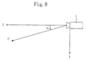
- the optical center of the camera 1 is defined as the origin O of the coordinate system; the optical axis of the camera 1 as the Z-axis thereof; horizontal and vertical directions as the X- and Y-axes thereof; an angle formed by a visual axis extending from the light source 2 to the point P with the X-axis as ⁇ ; an angle formed by a visual axis extending from the camera 1 to the point P with the X-axis as ⁇ ; and the coordinates of the light source 2 are (-D, 0, 0) (i.e., the baseline length is D).
- the distance calculator 6 calculates the distance Z as the only item of 3D information and outputs the result of this computation as a range image.
- all of the 3D coordinates (X, Y, Z) of the point P may be calculated by the following Equations (2) using the angle ⁇ shown in Figure 8 and output as the 3D information of the object.
- X Z / tan ⁇
- Y Z ⁇ tan ⁇
- the light intensity corrector 62a or 62b makes the correction simply by multiplying the light intensity data by the conversion ratio Ira/Isa or Irb/Isb .
- offset processing is preferably performed before this multiplication.
- offset processing may be performed on the reflected light image data stored on the image memory 61a or 61b by subtracting black level components (e.g., "10") from the image data. And then the image data is multiplied by the conversion ratio Ira/Isa or Irb/Isb .
- the values of the black level components should be estimated in advance just once. If such processing is performed, then the error of measurement may be reduced to about 10% compared to non-corrected data even if the emission intensity of the light source has varied by about 5%. That is to say, the correction can be made far more accurately.
- the offset processing may also be performed by subtracting the intensity of the reflected light image when no light is projected (i.e., when there is nothing but background light), not the black level components. In such a case, not only the effects of the background light but also those of the black level components can be compensated for, thus realizing even more accurate correction.
- Figure 9 illustrates another exemplary internal configuration for the distance calculator.
- the distance calculator 6A shown in Figure 9 includes, as an alternate light intensity corrector, a light-intensity-ratio-calculating LUT section 71 instead of the light intensity correctors 62a and 62b and the light intensity ratio calculator 63 shown in Figure 6 .
- a light-intensity-ratio-calculating LUT section 71 instead of the light intensity correctors 62a and 62b and the light intensity ratio calculator 63 shown in Figure 6 .
- multiple lookup tables (LUT's) are stored for respective conversion ratios.
- LUT's should be prepared for all the conversion ratios within a range needed to calculate the light intensity ratios such that every possible correction information supplied from the light source controller 5 can be processed. For example, if the emission intensities of the light sources 2a and 2b are variable with respect to the reference light intensities by ⁇ 5%, then the LUT's should be provided for all the conversion ratios in the range from 0.95 to 1.05. In each of the LUT's, data about the ratio of light intensities that have been corrected by the associated conversion ratio is stored for the data about the original light intensities.
- the LUT section 71 obtains a conversion ratio to be adopted for correction according to the correction information provided from the light source controller 5 and selects one of the LUT's associated with the conversion ratio obtained. Subsequently, the LUT section 71 extracts the light intensity data from the respective image memories 61a and 61b on a pixel-by-pixel basis, thereby directly obtaining a corrected light intensity ratio for each item of the light intensity data by reference to the selected LUT. Then, the LUT section 71 outputs the ratios to the range image generator 64 .
- the light sources 2a and 2b are flashed on the time-sharing basis.
- these light sources 2a and 2b may be flashed at the same time. In such a case, the measuring time can be shortened.
- the light beams emitted from the light sources 2a and 2b should have mutually different wavelengths and filters should be provided for the camera 1 to selectively receive the light beams with those particular wavelengths.
- the light receivers 21a and 21b are provided inside the light sources 2a and 2b , respectively.
- these light receivers 21a and 21b may be provided somewhere outside of the light sources 2a and 2b so long as the light intensities of the light sources 2a and 2b can be detected.
- the light receivers 21a and 21b are provided to detect the light intensities of the light sources 2a and 2b and thereby obtain the predetermined correction information.
- the light receivers do not have to be provided to obtain the correction information.
- Figure 10 illustrates an exemplary internal configuration for a distance calculator according to a modified example of the first embodiment.
- brightness in a predetermined region of the image captured by the camera 1 is used as the correction information
- the first light intensity corrector 62a uses, as the correction information, the brightness in a predetermined region of the captured image stored on the first image memory 61a .
- the second light intensity corrector 62b uses, as the correction information, the brightness in a predetermined region of the captured image stored on the second image memory 61b.
- an object with a reference brightness such as that of white paper may be disposed within an imaging area and the brightness of the object in the image captured may be used as the correction information.
- FIG 11 illustrates an arrangement of a rangefinder according to a second embodiment of the present invention.
- this rangefinder includes laser light sources 210A and 210B .
- a light source section 200 is made up of these laser light sources 210A and 210B , half mirror 102 and rotating mirror 104 .
- a camera section 300 is made up of the lens 107 , wavelength separating filters 108A and 108B , CCD's 109A and 109B and signal processors 110A and 110B .
- the x-y coordinate system will be used as a coordinate system for the visual field of a camera and the X-Y-Z coordinate system will be used as a coordinate system in real-world space to represent a 3D position.
- these coordinate systems will be simply referred to as “camera coordinate system” and “world coordinate system”, respectively.
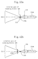
- Figures 12(a) and 12(b) illustrate an optical system for the light source 210A of the rangefinder shown in Figure 11 .
- a lens 211 is disposed between the laser light source 210A and the rotating mirror 104 .
- the lens 211 transforms the luminous flux emitted from the light source 210A into a slitlike light beam 212 and focuses the luminous flux on the center 104a of the rotating mirror 104 .
- the same optical system is also provided for the other light source 210B .
- the optical system shown in Figure 12(a) is in an ideal state, in which the focus 213 of the slitlike light beam 212 matches the center 104a of the rotating mirror 104 .
- the focus 213 of the slitlike light beam 212 does not always match the center 104a of the rotating mirror 104 as in the optical system shown in Figure 12(b) .
- the gap between the focus 213 and the center 104a might cause an error in distance measurement theoretically speaking.
- this gap can be relatively small and substantially negligible in practice, because the lookup table (LUT) is prepared such that an estimated distance of a reference plane matches a known Z coordinate.
- the rangefinder further includes an LUT holder 220 , in which multiple LUT's are stored.
- Each of these LUT's represents one-to-one correspondence between the intensity ratio of reflected parts of the light beams projected from the light sources 210A and 210B and the rotation angle of the rotating mirror (i.e., the projection angle of the light beams outgoing from the light sources 210A and 210B ).
- the distance calculator 230 selects one of the LUT's stored on the LUT holder 220 for each pixel location in the image captured by the camera, thereby generating a range image as 3D information using the LUT selected.
- a 3D information generator 400 is made up of the LUT holder 220 and the distance calculator 230 .
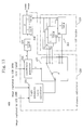
- Figure 13 illustrates respective internal configurations for the LUT holder 220 and distance calculator 230 .
- a light intensity ratio calculator 231 calculates a light intensity ratio in accordance with the data representing the images captured by the CCD's 109A and 109B on a pixel-by-pixel basis.
- a coordinate generator 232 In response to sync signals for the image data, a coordinate generator 232 generates x and y coordinates. Depending on the y coordinate generated by the coordinate generator 232 , an LUT selector 233 selects one of the LUT's 221 to be consulted.
- the light intensity ratio obtained by the light intensity ratio calculator 231 is converted into projection angle information 1/tan ⁇ .
- a converter 234 converts the x coordinate, which has been generated by the coordinate generator 232 , into camera angle information 1/tan ⁇ .
- Equation (3) is obtained by dividing the denominator and numerator of the right side of Equation (1) by tan ⁇ ⁇ tan ⁇ and is essentially the same as Equation (1).
- both ⁇ and ⁇ are set to the vicinity of 90 degrees during actual measurement.
- higher computational stability is attainable by using 1/tan ⁇ and 1/tan ⁇ as angle information than by using tan ⁇ and tan ⁇ , because tan ⁇ and tan ⁇ are indefinite when ⁇ and ⁇ are equal to 90 degrees.
- Supposing an item of light intensity data is composed of 8 bits and an item of projection angle information 1/tan ⁇ output from each LUT 221 is made up of 2 bytes, the size of a single LUT 221 is approximately 130 KB ( ⁇ 2 8 ⁇ 2 8 ⁇ 2).
- the 3D coordinates (X, Y, Z) are obtained basically as already described with reference to Figure 27 .
- the operation of this rangefinder is characterized by selectively using one of the LUT's for each pixel location in the camera image in deriving the projection angle ⁇ of the light.
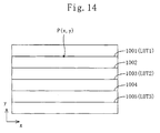
- FIG 14 schematically illustrates a correspondence between a camera image and LUT's.
- CCD lines 1001 through 1005 are illustrated for the sake of simplicity.
- LUT's 1, 2 and 3 have been prepared for the CCD lines 1001 , 1003 and 1005 , respectively.
- LUT's may be provided for around 10 CCD lines. These LUT's should be prepared while this rangefinder is being designed or fabricated.
- each LUT provided is associated an epipolar line.
- the "epipolar line” means a line appearing on a camera image when a line in the space is imaged.
- the line in the space results from the linear laser light that has been projected from the light source.
- the camera is placed at such a position that the respective CCD lines 1001 through 1005 are aligned with these epipolar lines, i.e., such that the epipolar lines extend horizontally on the camera image.
- the camera should be disposed such that the line connecting the center 107a of the camera lens 107 and the center 104a of the rotating mirror 104 is aligned with the X-axis of the world coordinate system and is parallel to the x-axis of the camera coordinate system.
- the distance calculator 230 determines which LUT should be used by not only calculating the light intensity ratio for each pixel in the image captured by each CCD but also obtaining the coordinates P(x, y) of the pixel P in the camera coordinate system. For example, if the pixel P in question is located on the CCD line 1001 as shown in Figure 14 , then the LUT 1 is adopted. In the same way, if the pixel P in question is located on the CCD line 1003 or 1005 , then the LUT 2 or 3 is adopted. On the other hand, if the pixel P in question is located on the CCD line 1002 with no associated LUT, then linear interpolation is carried out between the LUT's 1 and 2 provided for the nearest two CCD lines 1001 and 1003 .
- Figure 15 schematically illustrates the operating principle of the rangefinder according to the second embodiment based on the world coordinate system.
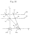
- Figure 16 is a simplified version of Figure 15 .
- the camera 1104 is disposed to meet the above-specified conditions. That is to say, the center 107a of the lens of the camera 1104 and the center 104a of the rotating mirror 104 are both located on the X-axis of the world coordinate system.
- a virtual light source 1105 is provided herein to illustrate the operating principle and to project linear laser radiation with the two types of light patterns such as those shown in Figure 25 on a time-sharing basis.
- FIG. 15 and 16 two reference planes CP1 and CP2 with Z coordinates of Z1 and Z2 (Z1 ⁇ Z2), respectively, are defined.
- Figure 15 only the respective upper halves of the reference planes CP1 and CP2 within the visual field of the camera 1104 are illustrated.
- the illustration of the other lower half of the camera visual field is omitted in Figure 15 for the sake of simplicity, because the lower half is symmetrical to the upper half.
- an angle formed by a vertical plane including a point in question and the rotation axis of the rotating mirror 104 with the X-axis is defined as ⁇ .
- the angle formed between a vertical plane VPA including a point PA1 in question and the rotation axis of the rotating mirror 104 and the X-axis is ⁇ A
- the angle formed between a vertical plane VPB including another point PB1 in question and the rotation axis of the rotating mirror 104 and the X-axis is represented as ⁇ B .
- an angle formed by the projective line of a line connecting a point in question to a viewpoint (i.e., the center 107a of the lens or the center 104a of the rotating mirror) on the YZ plane with the Z-axis is herein defined as an angle of elevation ⁇ .
- the centers 107a and 104a of the lens and the rotating mirror are both located on the X-axis to meet the positional conditions of the camera.
- the angle of elevation associated with a point as viewed from the center 107a of the lens is always equal to that associated with the point as viewed from the center 104a of the rotating mirror.
- the angle ⁇ is defined as shown in Figure 15 .
- the linear laser radiation emitted from the light source 1105 is reflected at the center 104a of the rotating mirror and is made to sweep the object as the rotating mirror 104 rotates. Also, as the light source 1105 changes its angle, the emission angle ⁇ L of the linear laser radiation also changes gradually. This emission angle ⁇ L corresponds to the angle of elevation ⁇ .
- Such a light source 1105 is supposed here to represent the lens-shading effects on the light actually projected from the light source section in the Y-axis direction. That is to say, the actual light source section sweeps the object by irradiating it with a slitlike light beam in parallel to the Y-axis, and the intensity of the projected light is supposed to change only in the sweeping direction (i.e., the X-axis direction). Actually, though, a so-called "lens-shading" phenomenon occurs. Specifically, the light intensity of the slitlike light beam attenuates in the peripheral regions compared to the center region thereof. For that reason, the light source 1105 is herein supposed to project linear laser radiation and the lens-shading phenomenon occurring in the real-world light source section is reproduced using the emission angle ⁇ L as a parameter.
- Figure 17 schematically illustrates relationships between the locations of respective points PA1, PA2, PB1 and PB2 on the camera image and a CCD line.
- the points PA1 and PA2 are intersections of linear light LA with a constant intensity ratio ⁇ A with the reference planes CP1 and CP2 , respectively.
- the points PB1 and PB2 are intersections of linear light LB with a constant intensity ratio ⁇ B with the reference planes CP1 and CP2 , respectively.
- the respective parts of the light LA that have been reflected from various points with mutually different Z coordinates are located on the single CCD line 1001 associated with the same y coordinate in the camera image.
- the x coordinates thereof are always different from each other.
- these points can be identified from each other based on the x coordinates.
- the LUT may be prepared in the following manner, for example.
- a reference plane (vertical plane) is disposed at a known Z coordinate and is irradiated with the light from the light sources 210A and 210B . Then, LUT's are made for respective y coordinates such that the measured distance of the reference plane matches the known Z coordinate.
- only a single reference plane may be prepared as a matter of principle. However, if an LUT is made using a plurality of reference planes, then the accuracy of measurement can be improved to a practical level.
- the LUT's may be prepared for all the CCD lines. Alternatively, as is done in the foregoing embodiment, the LUT's may be prepared selectively for some of the CCD lines at regular intervals. In that case, a substitute LUT may be formed for pixels on a CCD line associated with no LUT by performing linear interpolation on the LUT's provided for the closest, or vertically adjacent, CCD lines, for example.
- approximation of function may be carried out over the entire camera image using intensity ratios ⁇ and pixel locations (x, y) as parameters.
- the camera should be disposed to meet the conditions that the epipolar lines are parallel to the x-axis of the camera coordinate system and aligned with the CCD lines. Specifically, the camera needs to be positioned such that the line connecting the center 107a of the camera lens to the center 104a of the rotating mirror is aligned with the X-axis of the world coordinate system and is parallel to the x-axis of the camera coordinate system. Thus, the camera and the light sources cannot be disposed so freely.
- a rangefinder according to the third embodiment of the present invention is adapted to make the camera and light sources placeable more freely compared to the second embodiment.
- the basic arrangement and operation of the rangefinder of the third embodiment are the same as those described in the second embodiment.
- the third embodiment is different from the second embodiment in respects of how to dispose the camera, how to define the epipolar lines, how to make the LUT's and how the distance calculator works.
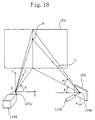
- Figure 18 is a schematic perspective view illustrating the operating principle of the rangefinder according to the third embodiment based on the world coordinate system.
- the camera is disposed to meet the following conditions.
- the center 107a of the lens of the camera 1104 is defined as the origin O of the world coordinate system.
- the optical axis of the camera 1104 is aligned with the Z-axis.
- the direction of the x-axis of the camera coordinate system i.e., the direction in which the CCD lines extend
- the center 104a of the rotating mirror does not have to be located on the X-axis.
- the camera and light sources can be disposed more freely than the second embodiment.
- the epipolar lines are not parallel to each other in the camera image as opposed to the second embodiment. Accordingly, to make an LUT, the shapes of the epipolar lines in the camera image should be identified first.
- Figures 19(a) and 19(b) illustrate the shapes of the epipolar lines according to the third embodiment.
- the epipolar lines radiate from a vanishing point S (xm, ym) as shown in Figure 19(b) .
- the shapes of these epipolar lines can be determined.
- angles ⁇ , ⁇ and ⁇ are defined as shown in Figure 18 .
- the angle ⁇ is not the angle of elevation as defined in the second embodiment but an angle formed by the unit direction vector u with the XZ plane.
- multiple (i.e., three in this example) linear light beams L1, L2 and L3 which have mutually different light intensity ratios ⁇ 1 , ⁇ 2 and ⁇ 3 and will result in different epipolar lines in the camera image, are projected from the center 104a of rotation onto a plurality of reference planes CP1 and CP2 with known Z coordinates Z1 and Z2 .
- These linear light beams L1 , L2 and L3 are reflected from the reference plane CP1 at points P11, P21 and P31 , and from the reference plane CP2 at points P12, P22 and P32 , respectively.
- Figure 19(b) illustrates where these six points P11 , P12, P21, P22, P31 and P32 of reflection and the epipolar lines associated with the three linear light beams L1, L2 and L3 between the two reference planes CP1 and CP2 are located on the camera image.
- the coordinates A (Xm, Ym, Zm) of the center 104a of the rotating mirror can be obtained from the world coordinates of the six points P11, P12, P21, P22, P31 and P32 .
- the coordinates (xm, ym) of the vanishing point S can be derived from the camera coordinates of the six points P11, P12, P21, P22, P31 and P32 as an intersection among the three epipolar lines.
- epipolar lines are drawn from the vanishing point S in desired directions and LUT's corresponding to these lines are made.
- LUT's LUT's
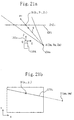
- Figure 20 is a simplified plan view illustrating a situation where a linear light beam LC with a constant intensity ratio ⁇ has been projected onto a point B with known coordinates on the reference plane CP1 .
- a single epipolar line 1701 is formed on the camera image by the linear light with the intensity ratio ⁇ 2 .
- the correspondence between the intensity ratio ⁇ and the rotation angle ⁇ and the correspondence between the intensity ratio ⁇ and the angle of elevation ⁇ in the vertical plane containing the line AB are defined for the point B .
- the correspondence between the intensity ratio ⁇ and the rotation angle ⁇ and the correspondence between the intensity ratio ⁇ and the angle of elevation ⁇ can also be defined in the same way for the other points on the epipolar line 1701 .
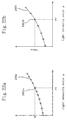
- Figures 22(a) and 22(b) illustrate information to be stored on an LUT associated with a single epipolar line.
- Figure 22(a) is a graph illustrating a relationship between the intensity ratio ⁇ and the angle of rotation ⁇
- Figure 22(b) is a graph illustrating a relationship between the intensity ratio ⁇ and the angle of elevation tan ⁇ .
- the points 1801a and 1801b correspond to the point B shown in Figures 21(a) and 21(b) .
- LUT's can be made in the same way for other desired epipolar lines.
- An LUT is selected based on the coordinates (x, y) of the point P in question in the camera coordinate system. And the vector ( cos ⁇ , tan ⁇ , sin ⁇ ) representing the direction from the light source toward the point P is known from the light intensity ratio ⁇ of the pixel associated with the point P by reference to the LUT selected.
- the camera and the light source can be disposed more freely according to the third embodiment than the second embodiment.
- the center 107a of the lens is supposed to be located at the origin O of the world coordinate system.
- the center 107a of the lens does not have to be defined as the origin O . Nevertheless, if the center 107a and the origin O are located at different positions, then corrections should be made on the coordinate system.
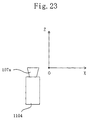
- Figure 23 illustrates a positional relationship between the origin O of the world coordinate system and the center 107a of the lens in this modified example.
- corrections may be made on the coordinate system by determining the positional relationship between the center 107a of the lens and the origin O according to a known camera calibration method (see Seiji Inoguchi and Kosuke Sato, "3D Imaging Techniques for Measurement", Shokodo, pp. 92-95).
- the following camera parameter matrix (18) is obtained by the known camera calibration method:
- a relationship as represented by the following Equation (19) is met between the camera coordinates (x, y) and the world coordinates (X, Y, Z):
- the position A (Xm, Ym, Zm) of the center 104a of the rotating mirror, the coordinates S (xm, ym) of the vanishing point and the LUT's are obtained as in the third embodiment.
- the Z coordinate of the point P in question can also be estimated basically in the same way as the third embodiment. However, instead of obtaining the intersection between the line represented by Equation (12) and the plane represented by Equation (14), the coordinates (X, Y, Z) are derived by solving the following Equation (20) using Equations (12) and (19):
- both x and y coordinates on the camera image are required.
- the camera and light source can be disposed even more freely.
- an LUT is provided for each predetermined epipolar line.
- an LUT may be provided for each and every pixel based on the same principle. However, some redundancy is unavoidable in such a case because the same information is contained in several LUT's.
- the accuracy of 3D information can be improved compared to the prior art by providing LUT's for respective y coordinates.
- LUT's may also be provided for respective x coordinates. Even so, the accuracy of 3D information obtained is still higher compared to providing just one LUT for the entire camera image.
- the second and third embodiments two light sources are provided.
- a single light source may be provided and two types of modulated light beams may be alternately projected at regular intervals, for example.
- the rangefinder according to the second or third embodiment uses the laser light sources and rotating mirror.
- the same effects are attainable according to the second and third embodiments even by using a pair of flash lamps as substitute light sources as in the first embodiment.
- the vertical gap between these two flash lamps should be as small as possible such that the epipolar lines resulting from the two flash lamps can be regarded as being substantially aligned with each other within the measurement range.
Landscapes
- Engineering & Computer Science (AREA)
- Physics & Mathematics (AREA)
- General Physics & Mathematics (AREA)
- Electromagnetism (AREA)
- Computer Networks & Wireless Communication (AREA)
- Radar, Positioning & Navigation (AREA)
- Remote Sensing (AREA)
- Business, Economics & Management (AREA)
- Tourism & Hospitality (AREA)
- Marketing (AREA)
- Educational Administration (AREA)
- Health & Medical Sciences (AREA)
- Economics (AREA)
- General Health & Medical Sciences (AREA)
- Human Resources & Organizations (AREA)
- Educational Technology (AREA)
- Primary Health Care (AREA)
- Strategic Management (AREA)
- General Business, Economics & Management (AREA)
- Theoretical Computer Science (AREA)
- Measurement Of Optical Distance (AREA)
- Length Measuring Devices By Optical Means (AREA)
Applications Claiming Priority (2)
| Application Number | Priority Date | Filing Date | Title |
|---|---|---|---|
| JP7259299 | 1999-03-17 | ||
| JP7259299 | 1999-03-17 |
Publications (2)
| Publication Number | Publication Date |
|---|---|
| EP1037069A2 true EP1037069A2 (fr) | 2000-09-20 |
| EP1037069A3 EP1037069A3 (fr) | 2004-01-14 |
Family
ID=13493831
Family Applications (1)
| Application Number | Title | Priority Date | Filing Date |
|---|---|---|---|
| EP00105549A Withdrawn EP1037069A3 (fr) | 1999-03-17 | 2000-03-16 | Télémètre |
Country Status (3)
| Country | Link |
|---|---|
| US (1) | US6441888B1 (fr) |
| EP (1) | EP1037069A3 (fr) |
| KR (1) | KR20000071453A (fr) |
Cited By (3)
| Publication number | Priority date | Publication date | Assignee | Title |
|---|---|---|---|---|
| EP1221582A3 (fr) * | 2001-01-05 | 2004-12-29 | Leuze electronic GmbH + Co. | Dispositif opto-électronique |
| CN103983961A (zh) * | 2014-05-20 | 2014-08-13 | 南京理工大学 | 一种3d激光雷达和摄像机联合标定立体标定靶 |
| TWI812493B (zh) * | 2022-09-28 | 2023-08-11 | 勝薪科技股份有限公司 | 測距裝置及其測距方法 |
Families Citing this family (34)
| Publication number | Priority date | Publication date | Assignee | Title |
|---|---|---|---|---|
| US6636627B1 (en) * | 1999-07-12 | 2003-10-21 | Fuji Photo Film Co., | Light source direction estimating method and apparatus |
| US6600168B1 (en) * | 2000-02-03 | 2003-07-29 | Genex Technologies, Inc. | High speed laser three-dimensional imager |
| US6618123B2 (en) * | 2000-10-20 | 2003-09-09 | Matsushita Electric Industrial Co., Ltd. | Range-finder, three-dimensional measuring method and light source apparatus |
| JP2002131016A (ja) * | 2000-10-27 | 2002-05-09 | Honda Motor Co Ltd | 距離測定装置、及び距離測定方法 |
| DE10063380B4 (de) * | 2000-12-19 | 2005-06-09 | Heraeus Med Gmbh | Verfahren und Vorrichtung zur Video-Aufnahme eines beleuchteten Feldes |
| US7310431B2 (en) * | 2002-04-10 | 2007-12-18 | Canesta, Inc. | Optical methods for remotely measuring objects |
| US6963671B2 (en) * | 2002-04-17 | 2005-11-08 | Mitsubishi Electric Research Labs, Inc. | Method for determining distances to a surface from a range image |
| AU2003252443A1 (en) * | 2002-08-01 | 2004-02-23 | Asahi Glass Company, Limited | Curved shape inspection method and device |
| JP2005067281A (ja) * | 2003-08-20 | 2005-03-17 | Toshiba Corp | 距離検出装置、エアバッグ制御装置および距離検出方法 |
| JP4230525B2 (ja) * | 2005-05-12 | 2009-02-25 | 有限会社テクノドリーム二十一 | 3次元形状計測方法およびその装置 |
| CA2670214A1 (fr) | 2006-11-21 | 2008-05-29 | Mantisvision Ltd. | Modelisation geometrique en 3d et creation de contenu video en 3d |
| US8090194B2 (en) | 2006-11-21 | 2012-01-03 | Mantis Vision Ltd. | 3D geometric modeling and motion capture using both single and dual imaging |
| KR100791389B1 (ko) * | 2006-12-26 | 2008-01-07 | 삼성전자주식회사 | 스트럭쳐드 라이트를 이용한 거리 측정 장치 및 방법 |
| WO2008120217A2 (fr) * | 2007-04-02 | 2008-10-09 | Prime Sense Ltd. | Cartographie de profondeur au moyen de profils projetés |
| WO2009115343A1 (fr) * | 2008-03-20 | 2009-09-24 | Cedes Ag | Détecteur destiné à la surveillance d'une zone de surveillance |
| JP2009250772A (ja) * | 2008-04-04 | 2009-10-29 | Sony Corp | 位置検出システム、位置検出方法、プログラム、物体判断システム、および物体判断方法 |
| US8531650B2 (en) * | 2008-07-08 | 2013-09-10 | Chiaro Technologies LLC | Multiple channel locating |
| CN101699313B (zh) * | 2009-09-30 | 2012-08-22 | 北京理工大学 | 基于摄像机和三维激光雷达的外部参数标定方法及系统 |
| KR20110116325A (ko) * | 2010-04-19 | 2011-10-26 | 삼성전자주식회사 | 영상 처리 장치 및 그 방법 |
| TWI407080B (zh) * | 2010-04-30 | 2013-09-01 | Quanta Comp Inc | 用以檢測三維感測器之系統及方法 |
| US8736676B2 (en) * | 2011-04-04 | 2014-05-27 | CyPhy Works, Inc. | Imaging based stabilization |
| JP2014163690A (ja) * | 2013-02-21 | 2014-09-08 | Mitsutoyo Corp | 形状測定装置 |
| WO2014145722A2 (fr) * | 2013-03-15 | 2014-09-18 | Digimarc Corporation | Photographie coopérative |
| US10473461B2 (en) * | 2013-04-01 | 2019-11-12 | Panasonic Intellectual Property Management Co., Ltd. | Motion-sensor device having multiple light sources |
| JP6223169B2 (ja) * | 2013-12-19 | 2017-11-01 | キヤノン株式会社 | 情報処理装置、情報処理方法およびプログラム |
| US9562760B2 (en) | 2014-03-10 | 2017-02-07 | Cognex Corporation | Spatially self-similar patterned illumination for depth imaging |
| US9536320B1 (en) * | 2014-12-23 | 2017-01-03 | John H. Prince | Multiple coordinated detectors for examination and ranging |
| US10571668B2 (en) | 2015-05-09 | 2020-02-25 | Cognex Corporation | Catadioptric projector systems, devices, and methods |
| US10445894B2 (en) * | 2016-05-11 | 2019-10-15 | Mitutoyo Corporation | Non-contact 3D measuring system |
| CN109635619B (zh) | 2017-08-19 | 2021-08-31 | 康耐视公司 | 用于三维重建的结构化光图案的编码距离拓扑 |
| US10699429B2 (en) | 2017-08-19 | 2020-06-30 | Cognex Corporation | Coding distance topologies for structured light patterns for 3D reconstruction |
| US10593055B2 (en) * | 2018-03-23 | 2020-03-17 | Capsovision Inc | Method and apparatus for capturing images and associated 3D model based on a single image sensor and structured-light patterns in the visible spectrum |
| DE102018133312B4 (de) * | 2018-12-21 | 2021-08-05 | Irlbacher Blickpunkt Glas Gmbh | Vorrichtung zur abstandsabhängigen Erkennung eines mobilen Objektes sowie Verfahren zu deren Betrieb |
| IL273779B2 (en) * | 2020-04-02 | 2024-10-01 | Yehuda Hai Vidal | Method and apparatus for mapping and ranging based on coherent-time comparison |
Family Cites Families (18)
| Publication number | Priority date | Publication date | Assignee | Title |
|---|---|---|---|---|
| US4594001A (en) * | 1981-07-07 | 1986-06-10 | Robotic Vision Systems, Inc. | Detection of three-dimensional information with a projected plane of light |
| US4744664A (en) * | 1986-06-03 | 1988-05-17 | Mechanical Technology Incorporated | Method and apparatus for determining the position of a feature of an object |
| US4895434A (en) * | 1986-07-11 | 1990-01-23 | Robotic Vision Systems, Inc. | Apparatus and method for 3-D measurement using holographic scanning |
| US5051906A (en) * | 1989-06-07 | 1991-09-24 | Transitions Research Corporation | Mobile robot navigation employing retroreflective ceiling features |
| US5280542A (en) * | 1989-12-28 | 1994-01-18 | Kabushiki Kaisha Toyota Chuo Kenkyusho | XYZ coordinates measuring system |
| US5064291A (en) * | 1990-04-03 | 1991-11-12 | Hughes Aircraft Company | Method and apparatus for inspection of solder joints utilizing shape determination from shading |
| EP0548079A1 (fr) * | 1990-05-25 | 1993-06-30 | Axiom Innovation Limited | Systeme d'acquisition d'images |
| GB9115537D0 (en) * | 1991-07-18 | 1991-09-04 | Secr Defence | An electro-optical detection system |
| US5608455A (en) * | 1992-07-30 | 1997-03-04 | Fuji Photo Film Co., Ltd | Interline transfer CCD image sensor with reduced dark current |
| US5682229A (en) * | 1995-04-14 | 1997-10-28 | Schwartz Electro-Optics, Inc. | Laser range camera |
| IL114278A (en) * | 1995-06-22 | 2010-06-16 | Microsoft Internat Holdings B | Camera and method |
| US6044170A (en) * | 1996-03-21 | 2000-03-28 | Real-Time Geometry Corporation | System and method for rapid shape digitizing and adaptive mesh generation |
| US5930383A (en) * | 1996-09-24 | 1999-07-27 | Netzer; Yishay | Depth sensing camera systems and methods |
| JP3732643B2 (ja) * | 1998-02-02 | 2006-01-05 | 松下電器産業株式会社 | レンジファインダ装置及び画像伝送装置 |
| US6040910A (en) * | 1998-05-20 | 2000-03-21 | The Penn State Research Foundation | Optical phase-shift triangulation technique (PST) for non-contact surface profiling |
| JP4111592B2 (ja) * | 1998-06-18 | 2008-07-02 | コニカミノルタセンシング株式会社 | 3次元入力装置 |
| US6313902B1 (en) * | 1998-12-21 | 2001-11-06 | Fuji Photo Film Co. Ltd. | Image processing method and apparatus |
| US6137566A (en) * | 1999-02-24 | 2000-10-24 | Eoo, Inc. | Method and apparatus for signal processing in a laser radar receiver |
-
2000
- 2000-03-16 EP EP00105549A patent/EP1037069A3/fr not_active Withdrawn
- 2000-03-17 KR KR1020000013508A patent/KR20000071453A/ko not_active Withdrawn
- 2000-03-17 US US09/527,476 patent/US6441888B1/en not_active Expired - Lifetime
Cited By (3)
| Publication number | Priority date | Publication date | Assignee | Title |
|---|---|---|---|---|
| EP1221582A3 (fr) * | 2001-01-05 | 2004-12-29 | Leuze electronic GmbH + Co. | Dispositif opto-électronique |
| CN103983961A (zh) * | 2014-05-20 | 2014-08-13 | 南京理工大学 | 一种3d激光雷达和摄像机联合标定立体标定靶 |
| TWI812493B (zh) * | 2022-09-28 | 2023-08-11 | 勝薪科技股份有限公司 | 測距裝置及其測距方法 |
Also Published As
| Publication number | Publication date |
|---|---|
| US6441888B1 (en) | 2002-08-27 |
| EP1037069A3 (fr) | 2004-01-14 |
| KR20000071453A (ko) | 2000-11-25 |
Similar Documents
| Publication | Publication Date | Title |
|---|---|---|
| US6441888B1 (en) | Rangefinder | |
| US11105617B2 (en) | Hybrid light measurement method for measuring three-dimensional profile | |
| US9170097B2 (en) | Hybrid system | |
| US6600168B1 (en) | High speed laser three-dimensional imager | |
| US9329035B2 (en) | Method to compensate for errors in time-of-flight range cameras caused by multiple reflections | |
| KR101605386B1 (ko) | 측정 물체 표면 위에서 3d 좌표들을 결정하기 위한 광학 측정 방법 및 측정 시스템 | |
| US6721679B2 (en) | Distance measuring apparatus and distance measuring method | |
| US11073379B2 (en) | 3-D environment sensing by means of projector and camera modules | |
| EP1596158A1 (fr) | Dispositif pour déterminer la forme d'un objet en trois dimensions | |
| CN1253636A (zh) | 远心光阑3维照相机及方法 | |
| KR20180032989A (ko) | ToF(time of flight) 촬영 장치 및 다중 반사에 의한 깊이 왜곡 저감 방법 | |
| JP2001116526A (ja) | 3次元形状計測装置 | |
| Fuchs et al. | Compensation for multipath in tof camera measurements supported by photometric calibration and environment integration | |
| WO2019008330A1 (fr) | Compensation de mouvement dans un éclairage de lumière structurée à décalage de phase permettant de mesurer des dimensions d'objets susceptibles de se déplacer librement | |
| CN103486979A (zh) | 混合系统 | |
| JPH1194520A (ja) | 実時間レンジファインダ | |
| JP2000147604A (ja) | レンジファインダ | |
| JP3517628B2 (ja) | レンジファインダ装置 | |
| CN110007289A (zh) | 一种基于飞行时间深度相机的运动伪差减小方法 | |
| WO2005100910A1 (fr) | Méthode de mesure d'une forme en trois dimensions et son équipement | |
| JP2006337254A (ja) | 撮像装置、撮像画像距離測定方法、撮像画像距離測定プログラム、及び記録媒体 | |
| JP3672731B2 (ja) | レンジファインダ装置 | |
| JP7438555B2 (ja) | 三次元計測方法および三次元計測装置 | |
| JPH1038511A (ja) | 照明方法および照明装置 | |
| JP3711808B2 (ja) | 形状計測装置および形状計測方法 |
Legal Events
| Date | Code | Title | Description |
|---|---|---|---|
| PUAI | Public reference made under article 153(3) epc to a published international application that has entered the european phase |
Free format text: ORIGINAL CODE: 0009012 |
|
| AK | Designated contracting states |
Kind code of ref document: A2 Designated state(s): AT BE CH CY DE DK ES FI FR GB GR IE IT LI LU MC NL PT SE |
|
| AX | Request for extension of the european patent |
Free format text: AL;LT;LV;MK;RO;SI |
|
| PUAL | Search report despatched |
Free format text: ORIGINAL CODE: 0009013 |
|
| AK | Designated contracting states |
Kind code of ref document: A3 Designated state(s): AT BE CH CY DE DK ES FI FR GB GR IE IT LI LU MC NL PT SE |
|
| AX | Request for extension of the european patent |
Extension state: AL LT LV MK RO SI |
|
| 17P | Request for examination filed |
Effective date: 20040301 |
|
| AKX | Designation fees paid |
Designated state(s): DE FR GB IT |
|
| STAA | Information on the status of an ep patent application or granted ep patent |
Free format text: STATUS: THE APPLICATION HAS BEEN WITHDRAWN |
|
| 18W | Application withdrawn |
Effective date: 20061222 |