EP1037400A2 - Réduction par des décalages de codes d'une réception inadéquate de canal adjacent sur une liaison montante dans un système de communication utilisant un satellite effectuant des traitements d'informations - Google Patents
Réduction par des décalages de codes d'une réception inadéquate de canal adjacent sur une liaison montante dans un système de communication utilisant un satellite effectuant des traitements d'informations Download PDFInfo
- Publication number
- EP1037400A2 EP1037400A2 EP00104577A EP00104577A EP1037400A2 EP 1037400 A2 EP1037400 A2 EP 1037400A2 EP 00104577 A EP00104577 A EP 00104577A EP 00104577 A EP00104577 A EP 00104577A EP 1037400 A2 EP1037400 A2 EP 1037400A2
- Authority
- EP
- European Patent Office
- Prior art keywords
- uplink
- stagger
- data
- coded
- value
- Prior art date
- Legal status (The legal status is an assumption and is not a legal conclusion. Google has not performed a legal analysis and makes no representation as to the accuracy of the status listed.)
- Granted
Links
- 238000004891 communication Methods 0.000 title claims description 14
- 238000012545 processing Methods 0.000 title description 5
- 230000000116 mitigating effect Effects 0.000 title description 3
- 238000000034 method Methods 0.000 claims abstract description 44
- 230000001939 inductive effect Effects 0.000 claims 2
- 208000011580 syndromic disease Diseases 0.000 description 13
- 230000005540 biological transmission Effects 0.000 description 11
- 125000004122 cyclic group Chemical group 0.000 description 8
- 238000010586 diagram Methods 0.000 description 5
- 238000012986 modification Methods 0.000 description 3
- 230000004048 modification Effects 0.000 description 3
- 230000010287 polarization Effects 0.000 description 3
- 239000003086 colorant Substances 0.000 description 2
- 238000012937 correction Methods 0.000 description 2
- 230000000694 effects Effects 0.000 description 2
- 230000002238 attenuated effect Effects 0.000 description 1
- 230000015572 biosynthetic process Effects 0.000 description 1
- 230000010267 cellular communication Effects 0.000 description 1
- 230000007423 decrease Effects 0.000 description 1
- 230000003111 delayed effect Effects 0.000 description 1
- 230000002939 deleterious effect Effects 0.000 description 1
- 230000001419 dependent effect Effects 0.000 description 1
- 238000011161 development Methods 0.000 description 1
- 239000000203 mixture Substances 0.000 description 1
- 230000000063 preceeding effect Effects 0.000 description 1
- 238000012546 transfer Methods 0.000 description 1
Images


Classifications
-
- H—ELECTRICITY
- H04—ELECTRIC COMMUNICATION TECHNIQUE
- H04B—TRANSMISSION
- H04B7/00—Radio transmission systems, i.e. using radiation field
- H04B7/14—Relay systems
- H04B7/15—Active relay systems
- H04B7/185—Space-based or airborne stations; Stations for satellite systems
- H04B7/1851—Systems using a satellite or space-based relay
- H04B7/18513—Transmission in a satellite or space-based system
Definitions
- the present invention relates to mitigation of false co-channel uplink reception (also known as "show-thru") in a satellite communication system.
- the present invention relates to staggering data transmissions in uplink beams to allow a receiving satellite to reliably discard show-thru signals.
- a multi-beam satellite system may transmit and receive numerous beams distinguished by the frequency and polarization of the signals present in the beam.
- the same frequency, same polarization beams i.e., the same "color" beams
- Beam reuse renders the same color beams susceptible to co-channel interference such that a portion of the signal from a beam B is observed in a beam A.
- co-channel interference arises primarily because of the practical limitations in implementing an antenna system which, ideally, would provide perfect rejection of same-color signals from other than the desired beam.
- the coverage provided for beam A inevitably provides some response to signals originating in beam B due to real world limitations in the physical realization of the antenna system.
- 12, 16, or more beams of the same color may be reused over a coverage area, correspondingly increasing the potential for CCI in any one of the beams.
- Processing satellite systems may further employ TDMA (time division multiple access) techniques that permit several user earth terminals to time share a frequency channel by sending short traffic bursts in assigned time slots. These bursts typically exploit powerful error correcting codes to ensure the integrity of the traffic being carried. However, when the time slots in two same-color beams, A & B, are time aligned, a phenomenon known as show-thru may occur.
- TDMA time division multiple access
- Another object of the present invention is to provide a simple and effective method of reliably discarding show-thru signals at a receiver.
- Yet another object of the present invention is to use the cyclic nature of error correcting codes in a staggered transmission system to reliably discard show-thru signals at a receiver.
- a predetermined set of staggering values for each same color uplink beam in a predetermined reuse plan may be generated.
- the staggering values may then be distributed among the user earth terminals generating the uplinks in the reuse plan.
- the method may use a full length error correcting code capable of correcting t errors.
- the method generally selects an uplink B stagger value differing from the uplink A stagger value by more than t codeword symbols.
- the uplink A stagger value may be zero and the uplink B stagger value may be t+1.
- the method may use a shortened error correcting code capable of correcting t errors.
- the method generally selects an uplink B stagger value differing from the uplink A stagger value by at least one codeword symbol.
- a difference in staggering value of more than t codeword symbols is also appropriate.
- the method is not limited to any particular number of uplink beams and thus, for example, the method may also select an uplink C stagger value differing from the uplink A stagger value and differing from the uplink B stagger value, code the uplink C data, and transmit the uplink C data staggered by the uplink C stagger value, in a separate uplink C.
- Figure 1 illustrates a satellite cellular communication system 100 including a frequency reuse plan 102 generated by a satellite 104.
- the frequency reuse plan 102 may make use of multiple frequencies and polarizations (for example, differently colored beams A and A* in Figure 1) to reduce interference between cells.
- the reuse plan 102 includes multiple cells 106-112, for example, that correspond to spot beams separately transmitted (as a downlink) and received (as an uplink) by the satellite 104 and received and transmitted by user earth terminals (UETs).
- UATs user earth terminals
- Figure 1 shows that multiple identically colored beams may exist in the frequency reuse plan 102.
- the cells 106 (supported by beam A) and 110 (supported by beam B) share the same color and are therefore candidates for CCI and show-thru.
- the cells 114-122 all share the same color as the cells 108 and 110.
- the discussion below proceeds with reference to beams A and B, it is noted that the techniques discussed below are also applicable to numerous additional same color beams in any frequency reuse plan.
- satellite communication signals typically employ highly effective error correction codes.
- a concatenated code may be applied to a raw data word before transmission.
- the concatenated coding process typically applies a first (outer) block code followed by a second (inner) convolutional code.
- the block code may, for example, be a Reed-Solomon block code.
- n the total length of a codeword
- k the number of information bytes in the codeword
- k n - 2*t where t is the number of (byte) errors the code can correct.
- the present invention exploits the cyclic property of codewords.
- cyclic codewords including, for example Reed-Solomon codewords
- a cyclic permutation of the symbols in one codeword generates a new codeword.
- the cyclic property as explained in more detail below, may be used in both full length and shortened codewords to greatly reduce show-thru.
- FIG 2 that figure shows a data diagram 200 of show-thru reception in uplink A of a staggered codeword from uplink B.
- Term Explanation z The current decoding epoch (i.e., the time during which the z th codeword in uplink A is being decoded).
- a z (X) The observable processed by the uplink A receiver during the uplink A epoch z.
- B z (X) The codeword transmitted in uplink B during uplink B epoch z.
- B z,m The m th byte of the uplink B epoch z codeword.
- Figure 2 illustrates uplink A decoding windows z-1 (reference 202), z (reference 204), and z+1 (reference 206), each n bytes in length.
- Figure 2 also illustrates uplink B transmission epochs z-1 (reference 208), z (reference 210), and z+1 (reference 212).
- the missed codeword symbols 214 and the substituted codeword symbols 216 are also illustrated.
- the data received in uplink A during epoch z is shown both as an observable 218 and a codeword plus errors 220.
- the resultant error pattern syndrome 222 induced by the stagger is also illustrated.
- the uplink B codewords are staggered by s codeword symbols from the uplink A codewords.
- the uplink B codewords are delayed during transmission (i.e., arrive "late” during show-thru in the receiver for uplink A).
- uplink A codewords rather, are early with respect to uplink B codewords, the primary importance is not in relative terms like “early” or "late”, but in the concept of staggering to prevent uplink codewords (among any number of beams) from arriving in coextensive decoding windows.
- the uplink A observable 218 will encompass portions of two codewords from beam B.
- the first term in the right hand side (rhs) of equation (1) indicates that the last component (i.e., the high order term) of the uplink B epoch z-1 codeword appears as the low order term in the uplink A decoding window.
- the last term in the rhs cancels the high order term of the uplink B epoch z codeword (which will subsequently appear in the uplink A epoch z+1 decoding window 206).
- Equation (3) asserts that, when the uplink B codeword is staggered one codeword symbol late relative to the uplink A codewords, the result appears to the uplink A decoder as a codeword with a possible error in position 0.
- a z (X) is formed from n-1 codeword symbols of the staggered B z (X) (these match another codeword) and a potential error in the low order codeword symbol.
- the error has a magnitude of (B z-1,n-1 ⁇ B z,n-1 ), which is the XOR of the high order components of the uplink B epoch z-1 codeword and the uplink B epoch z codeword.
- the observable A z (X) will decode satisfactorily in a t error correcting Reed-Solomon decoder because the observable contains at most a single error. In other words, at most, one byte is in error (neglecting noise and other sources of interference) although the byte may be in error in many bits.
- the observable A z (X) 218 is thus formed from the s codeword symbols from the uplink B z-1 epoch codeword, followed by n-s codeword symbols from the uplink B epoch z codeword.
- the high order s codeword symbols from the uplink B epoch z codeword are lost (and represent, for example, missed codeword symbols 214) and the high order s codeword symbols from the uplink B epoch z-1 form part of the uplink A observable 218 (and represent, for example, the substituted codeword symbols 216).
- the uplink A observable A z (X) represents a codeword plus errors 220 presented to the uplink A decoder, with a corresponding error syndrome 222.
- decoder failure may be used to discard uplink A observables present due to show-thru from the uplink B. In other words, show-thru is prevented, with a very high probability, when the uplink B is staggered by more than t codeword symbols from other uplinks, including the uplink A.
- a potential show-thru uplink B codeword (presented as an uplink A observable) reaches the uplink A decoder with 13 or more of its 255 (byte) symbols in error when the stagger is 13 or more codewords between the uplink A and the uplink B.
- the probability that the uplink A Reed-Solomon decoder will not produce a decode failure is less than 1.5 parts per billion. This probability is consistent with the typical requirement for Cell Misinsertion Ratio (CMR) in an ATM network and, as a result, allows satellites to reliably receive and process ATM cells.
- CMR Cell Misinsertion Ratio
- Equations (4) through (7) above may be modified for the case where the stagger is early.
- the corresponding equations (8) through (11) are presented below:
- a z (X) B z,s (X)*X ⁇ -s ⁇ X ⁇ -s*B z (X) ⁇ B z+1,s (X)*X ⁇ (n-s)
- C(X) B z,s (X)*X ⁇ -s ⁇ X ⁇ -s*B z (X) ⁇ B z,s (X)*X ⁇ (n-s)
- a z (X) C(X) ⁇ (B z,s (X) ⁇ B z+1,s (X))*X ⁇ (n-s)
- E(X) (B z,s (X) ⁇ B z+1,s (X)) *X ⁇ (n-s)
- Equation (8) reveals that the observable at the uplink A decoder is comprised of the uplink B epoch z codeword, excluding the first s codeword symbols (which are designed B z,s (X)), together with the first s codeword symbols of the uplink B epoch z+1 codeword, denoted B z+1,s (X).
- Equation (9) shows that B z,s (X), shifted cyclicly by s codeword symbols (in the opposite direction to the previous discussion with respect to equation (5), is also a codeword.
- Equation (10) illustrates that the uplink A observable A z (X) may be considered a codeword having some additional (error syndrome) components in its upper s codeword symbol positions.
- Equation (11) shows that the error syndrome E(X) may be categorized as an error pattern of up to s codeword symbol errors.
- the uplink A observable presented to the uplink A decoder will induce decoder failure with high probability when show-thru from B occurs with early stagger, provided that s>t.
- n 2 ⁇ v) - 1 .
- a shortened codeword may be thought of as having been formed by filling out the high order (2 ⁇ v) - 1 - n terms of the information bytes with zeroes, encoding the result to form a full length codeword, and truncating the result to the (shortened) length n by dropping the zero fill.
- a decoder need not consider the (assumed zero) high order terms of the shortened codeword.
- the received observable may be considered to be filled out with zeroes, decoded, and then the fill discarded.
- All codewords of a shortened code are also codewords in the full length code; however, not all codewords in the full length code, when truncated to the shortened value of n (e.g., 236), are codewords in the shortened code.
- Clark and Cain provide a discussion in Chapter 5 of decoding techniques, including the formation of syndromes, the error locator polynomial ⁇ (X), and the error evaluator polynomial ⁇ (X). Clark and Cain further provide a discussion of the Chien search and its implementation.
- the syndrome formed during the decoding process for the shortened decoder is the same as would be formed by the full length decoder when presented with an observable X ⁇ s*B z (X) ⁇ B z,s (X)*X ⁇ n .
- the term B z,s (X)*X ⁇ n serves algebraically to remove the s high order terms because the syndrome of X ⁇ s*B z (X) is zero for the full length code.
- the syndrome results in error locator and error evaluator polynomials ( ⁇ (X) and ⁇ (X)) that reflect the probable presence of errors in the s positions n through n + s - 1 . Because the process of forming ⁇ (X) and ⁇ (X)from the syndrome is the same for the full length decoder and for the shortened decoder, the same polynomials will be derived in either case.
- the Chien search portion of the decoding process is typically restricted to positions 0 through n-1 for a shortened codeword.
- the related roots of ⁇ (X) at locations with index of n or higher are not encountered in the decoding process.
- Decoder failure occurs because the number of roots of ⁇ (X) found in the search does not match the degree of ⁇ (X).
- decoder failure will occur in the shortened case as long as not all s terms of B z,s (X) are zero. If the s coefficients of B z,s (X) are independent, equally likely, random variables, then the probability that all s are zero is (2 ⁇ -v) ⁇ s , which is small for large s.
- the decoder for the shortened code knowing it is decoding a shortened code, restricts its search for roots to positions 0 through 235 and will, therefore find only 4 roots rather than the 8 required for a valid decode. This results in decoder failure and the discard of the show-thru from B.
- the degree of protection against show-thru afforded by the invention is essentially independent of the amount of CCI.
- the present invention does not depend in any way on the show-thru being small but only on the fact that the staggering generates, with high probability, more than t errors in an observable (or even a single error in high order codeword symbol positions assumed zero for a shortened code).
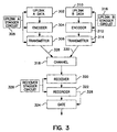
- the communication system 300 includes, generally on the ground, an uplink A data input 302, an uplink A encoder 304, an uplink A transmitter 306, and the uplink A stagger circuit 308.
- the communication system includes an uplink B data input 310, an uplink B encoder 312, an uplink B transmitter 314, and the uplink B stagger circuit 316.
- signals transmitted over the channel 318 are received and processed using a receiver 320, an uplink A decoder 322, a gate circuit 324, as controlled by the receiver stagger circuit 326.
- the uplink A data 302 arrives for transmission and may be stored in a buffer or the like.
- the uplink A coder 304 for example, a (236, 212) Reed-Solomon coder (optionally followed by an inner coder), produces coded uplink A data for transmission by the uplink A transmitter 306.
- the uplink A stagger circuit 308 may include clocks, for example, that control the clocking of data into the uplink A encoder 304, the clocking of the uplink A encoder 304, or the clocking of the uplink A transmitter 306 to introduce a predetermined amount of stagger in the uplink A 328.
- the stagger circuits 308, 316, 326 may be implemented in numerous ways. As noted above, the stagger circuits may generate or control clock signals. As another example, the stagger circuits (or any of the elements shown in Figure 3) may by incorporated into a single DSP, ASIC, or the like, and may comprise discrete circuitry that controls the encoders, decoders, transmitters, or receivers, for example, to introduce the appropriate stagger values in the uplinks.
- the uplink B coder 312 produces coded uplink B data for transmission by the uplink B transmitter 314.
- the uplink B stagger circuit 316 may control the clocking of data into the uplink B encoder 312, the clocking of the uplink B encoder 312, or the clocking of the uplink B transmitter 314 to introduce a predetermined amount of stagger in the uplink B 330.
- the uplink A stagger and the uplink B stagger differ, preferably, by more than t codeword symbols to prevent with near certainty successful decoding of show-thru data.
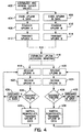
- the appropriate uplink decoding windows are established according to the stagger values noted above.
- the uplink A and the uplink B are received at steps 418, 420 (for example, by one or more antenna onboard a satellite).
- the signals received in the uplink A and B are subjected to demodulation and additional processing (not shown) to generate baseband uplink A data and uplink B data.
- the uplink A data and the uplink B data are applied to decoders at the decoding steps 422 and 424 which generate decoded A data and decoded B data, respectively.
- decoder failure results with very high probability because of staggering during show-thru (and, in general, whenever more than t errors are present in the data input to the decoder).
- the receiver checks for decoder failure, and if asserted, discards the decoded A or B data. Processing continues at the reception steps 416, 418.
- the absence of decoder failure is an extremely good indication that, as the case may be, the decoded A data or the decoded B data is correct data intended to be received by the uplink A receiver or the uplink B receiver.
- the resultant correct decoded A data may be switched, recoded, remodulated, and retransmitted to any appropriate destination.
- the resultant correct decoded B data may be switched, recoded, remodulated, and retransmitted to any appropriate destination.
- the decoding window for the uplink A may encompass partially noise or part or all of the overhead portion of bursts in the uplink B that are showing-thru.
- the case where part of the uplink A decoding window is overlapped by noise or by burst overhead is similar and the same coding properties that are effective with full overlap are applicable as discussed above.
- the effectiveness of the invention is not dependent on the level of show-thru (in terms of the resultant signal to noise ration) since it depends only on the property of a Reed-Solomon error control system to recognize, with high probability, a sequence that is beyond its decoding capability.
- noise will be present; however, since the probability of show-thru decreases with increasing noise level, the stagger method disclosed above is no less effective in terms of mitigating show-thru when noise is present.
- the present invention may be efficiently implemented in practice using staggered clocks between uplink processing and transmitting circuitry for same color beams. Furthermore, presently available encoders at the UET and matching decoders at the satellite may be used without modification and therefore blend seamlessly with the scrambling and descrambling of the present invention. With the addition of gate circuitry responsive to decoder failure indicators, the present invention greatly reduces show-thru with minimal impact on cost or complexity of a communication system.
Landscapes
- Engineering & Computer Science (AREA)
- Physics & Mathematics (AREA)
- Astronomy & Astrophysics (AREA)
- Aviation & Aerospace Engineering (AREA)
- General Physics & Mathematics (AREA)
- Computer Networks & Wireless Communication (AREA)
- Signal Processing (AREA)
- Radio Relay Systems (AREA)
- Error Detection And Correction (AREA)
- Detection And Prevention Of Errors In Transmission (AREA)
Applications Claiming Priority (2)
| Application Number | Priority Date | Filing Date | Title |
|---|---|---|---|
| US270572 | 1999-03-16 | ||
| US09/270,572 US6507926B1 (en) | 1999-03-16 | 1999-03-16 | Mitigation of false co-channel uplink reception in a processing satellite communication system using stagger |
Publications (3)
| Publication Number | Publication Date |
|---|---|
| EP1037400A2 true EP1037400A2 (fr) | 2000-09-20 |
| EP1037400A3 EP1037400A3 (fr) | 2003-04-23 |
| EP1037400B1 EP1037400B1 (fr) | 2005-11-23 |
Family
ID=23031859
Family Applications (1)
| Application Number | Title | Priority Date | Filing Date |
|---|---|---|---|
| EP00104577A Expired - Lifetime EP1037400B1 (fr) | 1999-03-16 | 2000-03-14 | Réduction par des décalages de codes d'une réception inadéquate de canal adjacent sur une liaison montante dans un système de communication utilisant un satellite effectuant des traitements d'informations |
Country Status (6)
| Country | Link |
|---|---|
| US (1) | US6507926B1 (fr) |
| EP (1) | EP1037400B1 (fr) |
| JP (1) | JP3476734B2 (fr) |
| AT (1) | ATE311046T1 (fr) |
| CA (1) | CA2300657C (fr) |
| DE (1) | DE60024161T2 (fr) |
Cited By (1)
| Publication number | Priority date | Publication date | Assignee | Title |
|---|---|---|---|---|
| DE102021109391B3 (de) | 2021-04-14 | 2022-08-25 | Infineon Technologies Ag | Multibytefehler-Erkennung |
Families Citing this family (12)
| Publication number | Priority date | Publication date | Assignee | Title |
|---|---|---|---|---|
| US6337980B1 (en) * | 1999-03-18 | 2002-01-08 | Hughes Electronics Corporation | Multiple satellite mobile communications method and apparatus for hand-held terminals |
| EP1316233B1 (fr) | 2000-08-02 | 2011-10-05 | ATC Technologies, LLC | Réutilisation coordonnée de fréquences d'un système terrestre et d'un système satellitaire. |
| US6859652B2 (en) | 2000-08-02 | 2005-02-22 | Mobile Satellite Ventures, Lp | Integrated or autonomous system and method of satellite-terrestrial frequency reuse using signal attenuation and/or blockage, dynamic assignment of frequencies and/or hysteresis |
| US7792488B2 (en) | 2000-12-04 | 2010-09-07 | Atc Technologies, Llc | Systems and methods for transmitting electromagnetic energy over a wireless channel having sufficiently weak measured signal strength |
| US6993288B2 (en) * | 2002-07-17 | 2006-01-31 | The Boeing Company | Managing satellite fixed beam uplink using virtual channel assignments |
| US8358971B2 (en) | 2002-07-23 | 2013-01-22 | Qualcomm Incorporated | Satellite-based programmable allocation of bandwidth for forward and return links |
| US7379758B2 (en) * | 2002-07-23 | 2008-05-27 | Qualcomm Incorporated | Satellite communication system constituted with primary and back-up multi-beam satellites |
| US7525934B2 (en) * | 2003-09-24 | 2009-04-28 | Qualcomm Incorporated | Mixed reuse of feeder link and user link bandwidth |
| US7173552B1 (en) * | 2003-10-01 | 2007-02-06 | Analog Devices, Inc. | High accuracy segmented DAC |
| US7995667B2 (en) * | 2004-02-13 | 2011-08-09 | Broadcom Corporation | Reduced latency concatenated reed solomon-convolutional coding for MIMO wireless LAN |
| US7774688B1 (en) * | 2006-10-11 | 2010-08-10 | Marvell International Ltd. | Hardware efficient decoding system for Bose, Ray-Chaudhuri, Hocquenghem (BCH) product codes |
| US10104677B2 (en) | 2017-03-13 | 2018-10-16 | Microsoft Technology Licensing, Llc | Code shortening at a secondary station |
Family Cites Families (11)
| Publication number | Priority date | Publication date | Assignee | Title |
|---|---|---|---|---|
| US3818442A (en) * | 1972-11-08 | 1974-06-18 | Trw Inc | Error-correcting decoder for group codes |
| DE3563807D1 (en) * | 1984-07-03 | 1988-08-18 | Ant Nachrichtentech | Tdma print-to-multipoint communication system |
| JPH0787424B2 (ja) * | 1993-06-30 | 1995-09-20 | 日本電気株式会社 | バースト信号送信システム |
| US5951709A (en) * | 1995-02-28 | 1999-09-14 | Kabushiki Kaisha Toshiba | Radio communication system using TDD scheme |
| US5745484A (en) * | 1995-06-05 | 1998-04-28 | Omnipoint Corporation | Efficient communication system using time division multiplexing and timing adjustment control |
| US6091936A (en) * | 1996-03-29 | 2000-07-18 | Ericsson Inc. | Method and apparatus for reducing co-channel interference |
| GB2317303B (en) * | 1996-09-09 | 1998-08-26 | I Co Global Communications | Communications apparatus and method |
| US6031846A (en) * | 1996-12-06 | 2000-02-29 | Philips Electronics North America Corp. | Method and apparatus for improved time division multiple access (TDMA) communication |
| US6240083B1 (en) * | 1997-02-25 | 2001-05-29 | Telefonaktiebolaget L.M. Ericsson | Multiple access communication network with combined contention and reservation mode access |
| SE518224C2 (sv) * | 1997-06-24 | 2002-09-10 | Ericsson Telefon Ab L M | Sätt och system i ett cellbaserat nät |
| US6138261A (en) * | 1998-04-29 | 2000-10-24 | Trw Inc. | Concatenated coding system for satellite communications |
-
1999
- 1999-03-16 US US09/270,572 patent/US6507926B1/en not_active Expired - Lifetime
-
2000
- 2000-03-14 DE DE60024161T patent/DE60024161T2/de not_active Expired - Fee Related
- 2000-03-14 AT AT00104577T patent/ATE311046T1/de not_active IP Right Cessation
- 2000-03-14 EP EP00104577A patent/EP1037400B1/fr not_active Expired - Lifetime
- 2000-03-14 CA CA002300657A patent/CA2300657C/fr not_active Expired - Fee Related
- 2000-03-15 JP JP2000072187A patent/JP3476734B2/ja not_active Expired - Fee Related
Cited By (1)
| Publication number | Priority date | Publication date | Assignee | Title |
|---|---|---|---|---|
| DE102021109391B3 (de) | 2021-04-14 | 2022-08-25 | Infineon Technologies Ag | Multibytefehler-Erkennung |
Also Published As
| Publication number | Publication date |
|---|---|
| EP1037400A3 (fr) | 2003-04-23 |
| ATE311046T1 (de) | 2005-12-15 |
| CA2300657A1 (fr) | 2000-09-16 |
| US6507926B1 (en) | 2003-01-14 |
| DE60024161D1 (de) | 2005-12-29 |
| JP2000295159A (ja) | 2000-10-20 |
| DE60024161T2 (de) | 2006-06-08 |
| JP3476734B2 (ja) | 2003-12-10 |
| CA2300657C (fr) | 2006-10-03 |
| EP1037400B1 (fr) | 2005-11-23 |
Similar Documents
| Publication | Publication Date | Title |
|---|---|---|
| US8683292B2 (en) | Method and system for providing low density parity check (LDPC) coding for scrambled coded multiple access (SCMA) | |
| US6507926B1 (en) | Mitigation of false co-channel uplink reception in a processing satellite communication system using stagger | |
| US6263466B1 (en) | System and method of separately coding the header and payload of a data packet for use in satellite data communication | |
| US6992992B1 (en) | Downlink beam hopping waveform | |
| US6707916B1 (en) | Mitigation of false co-channel uplink reception in a processing satellite communication system using scrambling sequences | |
| EP0722227A1 (fr) | Emetteur/récepteur en diversité à spectre étalé | |
| Sklar | A structured overview of digital communications-A tutorial review-part I | |
| JPH11112481A (ja) | ダイバシティシステムのためのデータ電送方法 | |
| Synchronization | Channel coding—summary of concept and rationale | |
| EP0989688B1 (fr) | Emetteur/récepteur en diversité à spectre étalé | |
| US20100316161A1 (en) | Method and apparatus for transmitting/receiving data using satellite channel | |
| Sklar | A structured overview of digital communications--A tutorial review--Part II | |
| EP0245781B1 (fr) | Système de codage/décodage enchaîné pour la protection contre les interférences de transmissions numériques par un amplificateur répéteur régénératif intermédiaire | |
| US20050088986A1 (en) | Systems and methods for distributing data | |
| US11632194B2 (en) | System and method for satellite communication in a helicopter | |
| Salkield et al. | SpaceJam: Protocol-aware Jamming Attacks against Space Communications | |
| Nakayama et al. | Cell discard and TDMA synchronization using FEC in wireless ATM systems | |
| EP3518436A1 (fr) | Architecture de système de communication par satellite pour traitement partiel amélioré | |
| Bhargava et al. | Coding theory and its applications in communication systems | |
| Alminde et al. | Robustness of Radio Link between AAU-CubeSat and Ground Station | |
| EP0769856A2 (fr) | Méthode et appareil pour relais entre satellites sans erreurs | |
| Ray | Robust message integrity for FANS 1 and CNS/ATM | |
| Kim | Throughput enhancement of frequency-hopping spread-spectrum network with adaptive antenna array and packet combining | |
| Spink et al. | An analysis of mitigation techniques to reduce the impact of nuisance jamming and interference on commercial satcom links supporting ATM network services | |
| CA2351001A1 (fr) | Longueur de trame de liaison descendante commune pour debits de codage differents selon la forme d'onde de saut |
Legal Events
| Date | Code | Title | Description |
|---|---|---|---|
| PUAI | Public reference made under article 153(3) epc to a published international application that has entered the european phase |
Free format text: ORIGINAL CODE: 0009012 |
|
| AK | Designated contracting states |
Kind code of ref document: A2 Designated state(s): AT BE CH CY DE DK ES FI FR GB GR IE IT LI LU MC NL PT SE |
|
| AX | Request for extension of the european patent |
Free format text: AL;LT;LV;MK;RO;SI |
|
| PUAL | Search report despatched |
Free format text: ORIGINAL CODE: 0009013 |
|
| AK | Designated contracting states |
Designated state(s): AT BE CH CY DE DK ES FI FR GB GR IE IT LI LU MC NL PT SE |
|
| AX | Request for extension of the european patent |
Extension state: AL LT LV MK RO SI |
|
| 17P | Request for examination filed |
Effective date: 20030707 |
|
| RAP1 | Party data changed (applicant data changed or rights of an application transferred) |
Owner name: NORTHROP GRUMMAN CORPORATION |
|
| 17Q | First examination report despatched |
Effective date: 20031010 |
|
| RAP1 | Party data changed (applicant data changed or rights of an application transferred) |
Owner name: NORTHROP GRUMMAN CORPORATION |
|
| AKX | Designation fees paid |
Designated state(s): AT BE CH CY DE DK ES FI FR GB GR IE IT LI LU MC NL PT SE |
|
| GRAP | Despatch of communication of intention to grant a patent |
Free format text: ORIGINAL CODE: EPIDOSNIGR1 |
|
| GRAS | Grant fee paid |
Free format text: ORIGINAL CODE: EPIDOSNIGR3 |
|
| GRAA | (expected) grant |
Free format text: ORIGINAL CODE: 0009210 |
|
| AK | Designated contracting states |
Kind code of ref document: B1 Designated state(s): AT BE CH CY DE DK ES FI FR GB GR IE IT LI LU MC NL PT SE |
|
| PG25 | Lapsed in a contracting state [announced via postgrant information from national office to epo] |
Ref country code: IT Free format text: LAPSE BECAUSE OF FAILURE TO SUBMIT A TRANSLATION OF THE DESCRIPTION OR TO PAY THE FEE WITHIN THE PRESCRIBED TIME-LIMIT;WARNING: LAPSES OF ITALIAN PATENTS WITH EFFECTIVE DATE BEFORE 2007 MAY HAVE OCCURRED AT ANY TIME BEFORE 2007. THE CORRECT EFFECTIVE DATE MAY BE DIFFERENT FROM THE ONE RECORDED. Effective date: 20051123 Ref country code: NL Free format text: LAPSE BECAUSE OF FAILURE TO SUBMIT A TRANSLATION OF THE DESCRIPTION OR TO PAY THE FEE WITHIN THE PRESCRIBED TIME-LIMIT Effective date: 20051123 Ref country code: FI Free format text: LAPSE BECAUSE OF FAILURE TO SUBMIT A TRANSLATION OF THE DESCRIPTION OR TO PAY THE FEE WITHIN THE PRESCRIBED TIME-LIMIT Effective date: 20051123 Ref country code: AT Free format text: LAPSE BECAUSE OF FAILURE TO SUBMIT A TRANSLATION OF THE DESCRIPTION OR TO PAY THE FEE WITHIN THE PRESCRIBED TIME-LIMIT Effective date: 20051123 Ref country code: BE Free format text: LAPSE BECAUSE OF FAILURE TO SUBMIT A TRANSLATION OF THE DESCRIPTION OR TO PAY THE FEE WITHIN THE PRESCRIBED TIME-LIMIT Effective date: 20051123 Ref country code: CH Free format text: LAPSE BECAUSE OF FAILURE TO SUBMIT A TRANSLATION OF THE DESCRIPTION OR TO PAY THE FEE WITHIN THE PRESCRIBED TIME-LIMIT Effective date: 20051123 Ref country code: LI Free format text: LAPSE BECAUSE OF FAILURE TO SUBMIT A TRANSLATION OF THE DESCRIPTION OR TO PAY THE FEE WITHIN THE PRESCRIBED TIME-LIMIT Effective date: 20051123 |
|
| REG | Reference to a national code |
Ref country code: GB Ref legal event code: FG4D |
|
| REG | Reference to a national code |
Ref country code: CH Ref legal event code: EP |
|
| REF | Corresponds to: |
Ref document number: 60024161 Country of ref document: DE Date of ref document: 20051229 Kind code of ref document: P |
|
| REG | Reference to a national code |
Ref country code: IE Ref legal event code: FG4D |
|
| PG25 | Lapsed in a contracting state [announced via postgrant information from national office to epo] |
Ref country code: GR Free format text: LAPSE BECAUSE OF FAILURE TO SUBMIT A TRANSLATION OF THE DESCRIPTION OR TO PAY THE FEE WITHIN THE PRESCRIBED TIME-LIMIT Effective date: 20060223 Ref country code: SE Free format text: LAPSE BECAUSE OF FAILURE TO SUBMIT A TRANSLATION OF THE DESCRIPTION OR TO PAY THE FEE WITHIN THE PRESCRIBED TIME-LIMIT Effective date: 20060223 Ref country code: DK Free format text: LAPSE BECAUSE OF FAILURE TO SUBMIT A TRANSLATION OF THE DESCRIPTION OR TO PAY THE FEE WITHIN THE PRESCRIBED TIME-LIMIT Effective date: 20060223 |
|
| PG25 | Lapsed in a contracting state [announced via postgrant information from national office to epo] |
Ref country code: ES Free format text: LAPSE BECAUSE OF FAILURE TO SUBMIT A TRANSLATION OF THE DESCRIPTION OR TO PAY THE FEE WITHIN THE PRESCRIBED TIME-LIMIT Effective date: 20060306 |
|
| PG25 | Lapsed in a contracting state [announced via postgrant information from national office to epo] |
Ref country code: IE Free format text: LAPSE BECAUSE OF NON-PAYMENT OF DUE FEES Effective date: 20060314 |
|
| PGFP | Annual fee paid to national office [announced via postgrant information from national office to epo] |
Ref country code: FR Payment date: 20060317 Year of fee payment: 7 |
|
| PG25 | Lapsed in a contracting state [announced via postgrant information from national office to epo] |
Ref country code: MC Free format text: LAPSE BECAUSE OF NON-PAYMENT OF DUE FEES Effective date: 20060331 Ref country code: LU Free format text: LAPSE BECAUSE OF NON-PAYMENT OF DUE FEES Effective date: 20060331 |
|
| PG25 | Lapsed in a contracting state [announced via postgrant information from national office to epo] |
Ref country code: PT Free format text: LAPSE BECAUSE OF FAILURE TO SUBMIT A TRANSLATION OF THE DESCRIPTION OR TO PAY THE FEE WITHIN THE PRESCRIBED TIME-LIMIT Effective date: 20060424 |
|
| NLV1 | Nl: lapsed or annulled due to failure to fulfill the requirements of art. 29p and 29m of the patents act | ||
| REG | Reference to a national code |
Ref country code: CH Ref legal event code: PL |
|
| ET | Fr: translation filed | ||
| PLBE | No opposition filed within time limit |
Free format text: ORIGINAL CODE: 0009261 |
|
| STAA | Information on the status of an ep patent application or granted ep patent |
Free format text: STATUS: NO OPPOSITION FILED WITHIN TIME LIMIT |
|
| 26N | No opposition filed |
Effective date: 20060824 |
|
| REG | Reference to a national code |
Ref country code: IE Ref legal event code: MM4A |
|
| PGFP | Annual fee paid to national office [announced via postgrant information from national office to epo] |
Ref country code: DE Payment date: 20070430 Year of fee payment: 8 |
|
| GBPC | Gb: european patent ceased through non-payment of renewal fee |
Effective date: 20070314 |
|
| REG | Reference to a national code |
Ref country code: FR Ref legal event code: ST Effective date: 20071130 |
|
| PG25 | Lapsed in a contracting state [announced via postgrant information from national office to epo] |
Ref country code: GB Free format text: LAPSE BECAUSE OF NON-PAYMENT OF DUE FEES Effective date: 20070314 |
|
| PG25 | Lapsed in a contracting state [announced via postgrant information from national office to epo] |
Ref country code: FR Free format text: LAPSE BECAUSE OF NON-PAYMENT OF DUE FEES Effective date: 20070402 |
|
| PGFP | Annual fee paid to national office [announced via postgrant information from national office to epo] |
Ref country code: GB Payment date: 20060329 Year of fee payment: 7 |
|
| PG25 | Lapsed in a contracting state [announced via postgrant information from national office to epo] |
Ref country code: CY Free format text: LAPSE BECAUSE OF FAILURE TO SUBMIT A TRANSLATION OF THE DESCRIPTION OR TO PAY THE FEE WITHIN THE PRESCRIBED TIME-LIMIT Effective date: 20051123 |
|
| PG25 | Lapsed in a contracting state [announced via postgrant information from national office to epo] |
Ref country code: DE Free format text: LAPSE BECAUSE OF NON-PAYMENT OF DUE FEES Effective date: 20081001 |