EP1037421A2 - Procédé et dispositif de transmission de signaux SDH à bas débit utilisant une trame SDH à haut débit - Google Patents
Procédé et dispositif de transmission de signaux SDH à bas débit utilisant une trame SDH à haut débit Download PDFInfo
- Publication number
- EP1037421A2 EP1037421A2 EP99309423A EP99309423A EP1037421A2 EP 1037421 A2 EP1037421 A2 EP 1037421A2 EP 99309423 A EP99309423 A EP 99309423A EP 99309423 A EP99309423 A EP 99309423A EP 1037421 A2 EP1037421 A2 EP 1037421A2
- Authority
- EP
- European Patent Office
- Prior art keywords
- soh
- speed
- bytes
- frame
- speed sdh
- Prior art date
- Legal status (The legal status is an assumption and is not a legal conclusion. Google has not performed a legal analysis and makes no representation as to the accuracy of the status listed.)
- Withdrawn
Links
Images


Classifications
-
- H—ELECTRICITY
- H04—ELECTRIC COMMUNICATION TECHNIQUE
- H04J—MULTIPLEX COMMUNICATION
- H04J3/00—Time-division multiplex systems
- H04J3/02—Details
- H04J3/06—Synchronising arrangements
- H04J3/07—Synchronising arrangements using pulse stuffing for systems with different or fluctuating information rates or bit rates
- H04J3/076—Bit and byte stuffing, e.g. SDH/PDH desynchronisers, bit-leaking
-
- H—ELECTRICITY
- H04—ELECTRIC COMMUNICATION TECHNIQUE
- H04J—MULTIPLEX COMMUNICATION
- H04J3/00—Time-division multiplex systems
- H04J3/16—Time-division multiplex systems in which the time allocation to individual channels within a transmission cycle is variable, e.g. to accommodate varying complexity of signals, to vary number of channels transmitted
- H04J3/1605—Fixed allocated frame structures
- H04J3/1611—Synchronous digital hierarchy [SDH] or SONET
-
- Y—GENERAL TAGGING OF NEW TECHNOLOGICAL DEVELOPMENTS; GENERAL TAGGING OF CROSS-SECTIONAL TECHNOLOGIES SPANNING OVER SEVERAL SECTIONS OF THE IPC; TECHNICAL SUBJECTS COVERED BY FORMER USPC CROSS-REFERENCE ART COLLECTIONS [XRACs] AND DIGESTS
- Y10—TECHNICAL SUBJECTS COVERED BY FORMER USPC
- Y10S—TECHNICAL SUBJECTS COVERED BY FORMER USPC CROSS-REFERENCE ART COLLECTIONS [XRACs] AND DIGESTS
- Y10S370/00—Multiplex communications
- Y10S370/901—Wide area network
- Y10S370/902—Packet switching
- Y10S370/903—Osi compliant network
- Y10S370/907—Synchronous optical network, SONET
Definitions
- the present invention relates to a transmission method and apparatus which transmits low-speed SDH (synchronous digital hierarchy) signals using a high-speed SDH frame.
- SDH synchronous digital hierarchy
- WDM wavelength-division multiplexing
- TDM time-division multiplexed
- the dispersion shifted fiber (DSF), widely deployed in the field, is generally suitable for long-haul transmissions of high-speed signals but is not suited for the WDM systems. For this reason, when deploying the DSF, a high-speed TDM system is needed.
- the second problem of the WDM technology is that the WDM technology offers a bit-rate-free transmission but the efficiency of transmission attained by the WDM is higher when many high-speed signals (e.g., 10 Gbps) are transmitted than when low-speed signals (e.g., 2.4 Gbps) in the same number are transmitted. In order to meet the high-capacity demand, the higher transmission efficiency is preferred.
- FIG. 13 shows a configuration of high-speed WDM systems which are connected to low-speed electrically-multiplexed systems via working and protection optical-fiber cables.
- reference numerals 1(1) through 1(4) denote 2.4-Gbps electrically-multiplexed systems which includes four working channels #1 through #4 and one protection channel, both having a data rate of 2.4 Gbps.
- Reference numerals 2(1) through 2(5) denote high-speed WDM systems which use the wavelength multiplexing.
- Various optical-fiber cables accommodating the working and protection channels are connected between the 2.4-Gbps systems and the WDM systems. For example, an optical signal sent from one (the working channel #1) of the working channels #1-#4 of the 2.4-Gbps system 1(1) reaches the WDM system 2(1), and the WDM system 2(1) outputs a wavelength-multiplexed optical signal.
- Optical signals sent from the protection channels of the 2.4-Gbps systems 1(1) and 1(4) reach the WDM system 2(5), and the WDM system 2(5) outputs a wavelength-multiplexed signal.
- the WDM configuration of FIG. 13 offers a bit-rate-free transmission and makes the signal processing simple.
- the faulty WDM system is substituted for by the WDM system 2(5) by suitably switching the optical-fiber cables.
- the failure recover capability of 1 protection channel to 4 working channels is provided since all the optical signals of the working channels #1-#4 and the protection channel are transported to these WDM systems.
- FIG. 14 shows a configuration of a high-speed electrically-multiplexed system which is connected to a low-speed electrically-multiplexed system.
- reference numerals 1 denote 2.4-Gbps electrically-multiplexed systems which include four working channels #1 through #4 and one protection channel, both having a data rate of 2.4 Gbps.
- the two low-speed systems 1 are connected by an optical-fiber cable containing the working channels #1 through #4 and the protection channel.
- Reference numeral 3 denotes a 10-Gbps electrically-multiplexed system which has a data rate of 10 Gbps.
- the high-speed system 3 the four 2.4-Gbps signals sent by the low-speed system 1 are electrically multiplexed into a 10-Gbps high-speed signal, and then the high-speed multiplexed signal is converted into an optical signal.
- the high-speed system 3 transmits the optical signal on a first optical-fiber cable as the working channel, and regenerates an optical signal on a second optical-fiber cable as the protection channel.
- the low-speed system 1 which includes the four working channels #1 through #4 and one protection channel has a failure recovery capability of 80%, but the high-speed system 3 has only the failure recovery capability of 50%. That is, there is a problem in that the use of the high-speed electrically-multiplexed system 3 will lower the failure recovery capability. Further, when the vender of the low-speed systems 1 is different from the vendor of the high-speed system 3, the configuration of FIG. 14 does not necessarily assure the compatibility between the low-speed systems 1 and the high-speed system 3.
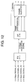
- FIG. 12 shows a multiplexing of four 2.4-Gbps signals into a 10-Gbps signal and demultiplexing of the 10-Gbps signal.
- a parallel-to-serial conversion (P/S) of 4 inputs to 1 output is provided at a transmit-side network element to multiplex the 2.4-Gbps signals #1 through #4 of the four channels into a 10-Gbps signal.
- This 10-Gbps signal is serially transported on an optical-fiber cable to a receive-side network element.
- a serial-to-parallel conversion (S/P) of 1 input to 4 outputs is provided at the receive-side network element to demultiplex the 10-Gbps signal into the reconstructed 2.4-Gbps signals #1 through #4.
- the correspondence between the reconstructed low-speed signals and their channels is unknown to the receive side of the network, and it is necessary that the number of channel for each of the input 2.4-Gbps signals is carried on the overhead of the 10-Gbps signal before the transmission.
- the frame synchronization is performed for a single channel of the low-speed signals reconstructed at the output of the S/P conversion with respect to a corresponding one of the known channel numbers.
- the channel number of the reconstructed low-speed signal of each channel is detected in this manner, and the channel allocation is controlled based on the detected channel number.
- the concept of the multiplexing method of FIG. 12 is analogous to the initial concept of the multiplexing method of the SONET. See TA-TSY-00253, Issue 2 published by Bellcore.
- the first problem is that the simple multiplexing of four 2.4-Gbps signals into a 10-Gbps signal does not assure the high-speed line error monitoring.
- the high-speed line error monitoring must be performed by using an optical power monitoring device or an optical spectrum-analyzer.
- the high-speed line error monitoring must be performed at the 10-Gbps systems by detecting the B1 byte (bit interleaved parity code) in the section overhead of a STS-N frame or a STM-N frame. Further, accessing the SDCC (section data communications channels) bytes in the section overhead of the high-speed SDH frame by the 10-Gbps systems is required to make it possible to remote control the optical transmission network elements by a control unit such as a workstation. For these reasons, it is difficult for the conventional systems to assure the high-speed line error monitoring when transmitting the low-speed SDH signals by using a high-speed SDH frame.
- the second problem of the multiplexing method of FIG. 12. is that the simple multiplexing of four 2.4-Gbps signals into a 10-Gbps signal does not directly assure the clock error adjusting. When a significant clock error between the incoming clock and the outgoing clock exists at the 10-Gbps systems, the clock error adjusting must be performed before transmitting the high-speed SDH frame.
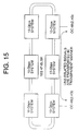
- FIG. 15 shows an optical transmission ring network in which high-speed transmission systems and a low-speed transmission system coexist.
- the 10-Gbps signal is transported on a main optical-fiber cable between the 10-Gbps systems. If the demand for transmitting 2.4-Gbps low-speed signals in a portion of the ring network by using the 10-Gbps high-speed signal occurs, the exact synchronization between the clock of the 10-Gbps systems and the clock of the 2.4-Gbps systems is not necessarily assured by simply placing the existing 2.4-Gbps low-speed systems in the network portion.
- the above demand may frequently occur when it is desired to upgrade the existing 2.4-Gbps systems of a vendor to the 10-Gbps systems of a different vendor simultaneously with the upgrading from the existing 2.4-Gbps optical-fiber cables to 10-Gbps optical-fiber cables.
- a clock frequency error of ⁇ 20 ppm between the incoming clock and the outgoing clock at a network element is allowed, and the AU (administration unit) pointers (the H1, H2 and H3 bytes) of the SONET frame are used to compensate for the possible frequency difference between the incoming clock and the outgoing clock.
- the AU pointers are located in the line overhead of the SONET frame not in the section overhead thereof, and the use of the AU pointers does not directly assure the high-speed line error monitoring nor the clock error adjusting.
- Embodiments of the present invention aim to provide an improved SDH signal transmission method and apparatus in which the above-mentioned problems are eliminated.
- Another aim is to provide a transmission method which executes the transmission of low-speed SDH signals using a high-speed SDH frame and ensures the clock error adjusting and the high-speed line error monitoring.
- Another aim is to provide a transmission apparatus which executes the transmission of low-speed SDH signals using a high-speed SDH frame and ensures the clock error adjusting and the high-speed line error monitoring.
- a transmission method which transmits low-speed SDH signals using a high-speed SDH frame
- the transmission method including the steps of: multiplexing the low-speed SDH signals into the high-speed SDH frame, the high-speed SDH frame including an information payload, a line overhead and a section overhead, the section overhead being divided into a first section overhead SOH and a second section overhead SOH, the first SOH carrying regenerator SOH bytes and the second SOH carrying multiplex SOH bytes; detecting the multiplex SOH bytes in the second SOH of the high-speed SDH frame without changing the line overhead and the payload when the high-speed SDH frame reaches a receive-side high-level line terminating equipment; and generating the multiplex SOH bytes in the second SOH of the high-speed SDH frame without changing the line overhead and the payload before the high-speed SDH frame is transmitted by a transmit-side high-level line terminating equipment.
- the above-mentioned aims may be achieved by a transmission apparatus which transmits low-speed SDH signals using a high-speed SDH frame
- the transmission apparatus including: a multiplexer which multiplexes the low-speed SDH signals into the high-speed SDH frame, the high-speed SDH frame including an information payload, a line overhead and a section overhead, the section overhead being divided into a first section overhead SOH and a second section overhead SOH, the first SOH carrying regenerator SOH bytes and the second SOH carrying multiplex SOH bytes; a multiplex SOH detecting unit which detects the multiplex SOH bytes in the second SOH of the high-speed SDH frame without changing the line overhead and the payload when the high-speed SDH frame reaches the transmission apparatus; and a multiplex SOH generating unit which generates the multiplex SOH bytes in the second SOH of the high-speed SDH frame without changing the line overhead and the payload before the high-speed SDH frame is transmitted by the transmission apparatus.
- the multiplex SOH bytes in the high-speed SDH frame are created and used by the high-speed line terminating equipment for clock error adjusting, high-speed line error monitoring, and high-speed line level equipment communications.
- the transmission method and apparatus of the present invention is effective in assuring the clock error adjusting and the high-speed line error monitoring when transmitting the low-speed SDH signals by using the high-speed SDH frame.
- the SDH (synchronous digital hierarchy) is a set of international digital transmission standards.
- the SDH is the international version of the SONET (synchronous optical network), which is used in North America.
- SONET synchronous optical network
- the fundamental principles of the SONET apply directly to the SDH.
- the two major differences between SDH and SONET are the terminology and the basic date rates used.
- the SONET uses a basic data rate of 51.84 Mbps
- the SDH uses a basic data rate of 155.52 Mbps, which is exactly three times the SONET basic data rate.
- the SONET specification is used as being in conformity with the SDH specification.
- the SONET specification defines a hierarchy of standardized digital data rates.
- Multiple STS-1 signals can be combined to a form an STS-N signal. This signal is created by interleaving bytes from "N" STS-1 signals that are mutually synchronized.
- STS-12 frame (622 Mbps) or the STS-48 frame (2.4 Gbps)
- the STS-192 frame (10 Gbps) is considered a high-speed SDH frame.
- the STS-12 frame is considered the high-speed SDH frame.
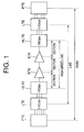
- FIG. 1 shows a transparent-transport SONET system to which an embodiment of the present invention is applied.
- PTE denotes path terminating equipment
- LTE denotes line terminating equipment
- HLTE denotes a high-speed line terminating equipment according to the invention
- STE denotes section terminating equipment.
- the LTE in the transparent-transport SONET system of FIG. 1 corresponds to a low-speed transmission apparatus having a data rate of 2.4 Gbps
- the HLTE in the transparent-transport SONET system of FIG. 1 corresponds to a high-speed transmission apparatus having a data rate of 10 Gbps, which is related to the present invention.
- FIG. 2 shows a conventional SONET system for the purpose of comparison with the transparent-transport SONET system of the present embodiment.
- the designation of reference characters such as PTE or LTE, which is the same as that of FIG. 1, is used.
- the SONET capabilities in the conventional SONET system are mapped into a three-layer hierarchy including section, line and path.
- a basic SONET frame (which is called the synchronous transport signal level-1 STS-1) is divided into an information payload, a path overhead (POH), a line overhead (LOH) and a section overhead (SOH).
- the payload is to be transported by the SONET system and is first mapped into a synchronous payload envelope (SPE). This operation is defined to be the path layer and is accomplished by using the path terminating equipment (PTE).
- PTE path terminating equipment
- POH path overhead
- the SPE After the formation of the SPE, the SPE is placed into the frame along with some additional overhead bytes, which are called the line overhead (LOH) bytes.
- LOH line overhead
- the LOH bytes are used to provide information for line protection and maintenance purposes. This LOH is created and used by the line terminating equipment (LTE).
- the next layer is defined as the section layer.
- the section layer is used to transport the STS-N frame over a physical medium such as an optical fiber cable.
- a regenerator section overhead (SOH) bytes Associated with the section layer are called the regenerator section overhead (SOH) bytes.
- the regenerator SOH bytes are used by the section terminating equipment (STE) for framing, section error monitoring, and section level equipment communications.
- the STE includes equipment which performs regeneration, and the regenerator terminates the regenerator SOH.
- the SDH specification defines a more detailed layer hierarchy than that of the SONET specification.
- the transmission method and apparatus of the present invention does not directly relate to the detailed layer structure of the SDH specification, and a description thereof will be omitted.
- a high-speed line layer is further defined.
- the SONET capabilities in the transparent-transport SONET system according to the invention are mapped into a four-layer hierarchy including section, high-speed line, line and path.
- the high-speed line layer is further defined as an additional intermediate layer between the section layer and the line layer.
- the HLTE is the high-speed line terminating equipment which corresponds to the 10-Gbps high-speed transmission apparatus of the present invention.
- the high-speed line layer is used to transport the high-speed SDH frame (or the STS-N frame) between the transmit-side HLTE and the receive-side HLTE.
- SOH multiplex section overhead
- the multiplex SOH bytes are created and used by the high-speed line terminating equipment (HLTE) for clock error adjusting, high-speed line error monitoring, and high-speed line level equipment communications.
- the line related signals including the payload, the pointers and the line overhead LOH bytes, which are the lower-level signals from a viewpoint of the high-speed-line related signals, are passed through the HLTE without modifications.
- the manner in which the line related signals are transported through the HLTE without modifications will be called the transparent transport.
- the transparent-transport SONET system of FIG. 1 when a high-speed SDH frame reaches the receive-side HLTE, the multiplex SOH bytes in the second SOH of the high-speed SDH frame are detected by the receive-side HLTE without changing the line overhead, the pointers and the payload, in order for high-speed line error monitoring and high-speed line level equipment communications.
- the multiplex SOH bytes in the second SOH of the high-speed SDH frame are generated by the transmit-side HLTE without changing the line overhead, the pointers and the payload before the high-speed SDH frame is transmitted by the transmit-side HLTE, in order for clock error adjusting, high-speed line error monitoring, and high-speed line level equipment communications.
- the transparent-transport SONET system of the present embodiment is effective in assuring the clock error adjusting and the high-speed line error monitoring when transmitting the low-speed SDH signals by using the high-speed SDH frame.
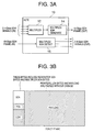
- FIG. 3A shows a configuration of the high-speed line terminating equipment (HLTE) in the transparent-transport SONET system of FIG. 1.
- HLTE high-speed line terminating equipment
- the HLTE 10 generally includes a multiplexer unit 12, a multiplex SOH generating unit 14, and a multiplex SOH detecting unit 16.
- the multiplexer unit 12 multiplexes low-speed (2.4 Gbps) SDH signals into a high-speed (10 Gbps) SDH frame, the high-speed SDH frame including an information payload, a line overhead and a section overhead, the section overhead being divided into a first section overhead SOH and a second section overhead SOH, the first SOH carrying regenerator SOH bytes and the second SOH carrying multiplex SOH bytes.
- the multiplex SOH detecting unit 16 detects the multiplex SOH bytes in the second SOH of the high-speed SDH frame without changing the line overhead and the payload when the high-speed SDH frame reaches the HLTE 10.
- the multiplex SOH generating unit 14 generates the multiplex SOH bytes in the second SOH of the high-speed SDH frame without changing the line overhead and the payload before the high-speed SDH frame is transmitted by the HLTE 10.
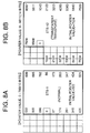
- FIG. 3B shows a SONET frame for explaining an operation of the high-speed line terminating equipment (HLTE) in the transparent-transport SONET system of FIG. 1.
- HLTE high-speed line terminating equipment
- the multiplex SOH bytes related to the HLTE are allocated to unused or undefined bytes of the section overhead SOH of the SONET frame.
- the regenerator SOH bytes in the SONET frame remain unchanged. That is, in the SONET frame used by the transparent-transport SONET system of the present embodiment, a portion of the section overhead SOH is used for the regenerator SOH bytes in the SONET frame, and another portion of the SOH is used for the multiplex SOH bytes related to the high-speed line layer (HLTE).
- the AU (administration unit) pointers, the LOH bytes and the payload (including the path overhead POH) are passed through the HLTE without modifications.
- the AU points, the LOH bytes and the payload are collectively called the line-related bytes.
- the line related bytes are the lower-level signals from a viewpoint of the high-speed-line related signals.
- a finite-size buffer inside the HLTE equipment When the incoming clock is running faster than the outgoing clock at the HLTE in the transparent-transport SONET system of the present embodiment, a finite-size buffer inside the HLTE equipment will begin to fill up. Lack of the capacity of the buffer for storing the incoming signal will occur.
- the buffer inside the HLTE equipment when the outgoing clock is running faster than the incoming clock at the HLTE, the buffer inside the HLTE equipment will start emptying. Vacant bytes in the buffer of the HLTE will increase. In these cases, if a clock error between the 2.4-Gbps signal and the 10-Gbps signal at the HLTE is not negligible, the size of the low-speed line layer is not equal to one fourth the size of the high-speed line layer. Hence, the buffer inside the HLTE will begin to fill up or will start emptying.
- the HLTE in the transparent-transport SONET system of the present embodiment adds stuffing bytes to the multiplex SOH of the SONET frame when multiplexing the 2.4-Gbps low-speed SDH signals of four channels into the 10-Gbps high-speed SDH frame.
- FIG. 4 shows stuffing bytes which are added to the multiplex section overhead bytes of the SONET frame by the HLTE of the transparent-transport SONET system of FIG. 1.
- the high-speed line terminating equipment (HLTE) in the present embodiment adds the stuffing bytes to the multiplex SOH bytes of the SONET frame when multiplexing the four 2.4-Gbps low-speed SDH signals (only three signals shown in FIG. 4, for the sake of convenience) into the 10-Gbps high-speed SDH frame.
- the addition of the stuffing bytes ensures the clock error adjustment even if a clock error occurs at the HLTE.
- the regenerator SOH bytes of the SONET frame for each of the four 2.4-Gbps low-speed SDH signals remain unchanged, and the multiplex SOH bytes are located at the undefined bytes of the section overhead of the SONET frame.
- the transmission method and apparatus of the present invention can eliminate the need for the stuffing byte removal and frame synchronization operations.
- the transparent-transport SONET system of FIG. 1 utilizes a pointer processing which eliminates the need for the stuffing byte removal and frame synchronization operations.
- the pointer used by the transparent-transport SONET system of the present embodiment indicates the start of one of the low-speed SDH signals relative to the start of the entire high-speed SDH frame.
- the stuffing byte removal and frame synchronization of the low-speed SDH signals at the receive-side HLTE is no longer needed because of the pointer processing.
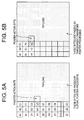
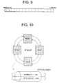
- FIG. 5A and FIG. 5B show a normal pointer processing of a conventional SONET system and a pointer processing of the transparent-transport SONET system of the present embodiment.
- the normal pointer processing of the conventional SONET system is performed by using the AU (administration unit) pointer bytes (H1, H2 and H3) in the section overhead of the conventional SONET frame.
- the normal pointer processing performed using the AU pointer bytes H1, H2 and H3 is known.
- the pointer bytes H1 and H2 contain a pointer value which indicates a start position of the payload in the SONET frame.
- the pointer byte H3 in the SOH of the SONET frame serves as a pointer action byte which is used for the normal pointer processing.
- the payload bytes indicated by the dotted area in FIG. 5A are passed without modification by the normal pointer processing.
- the pointer processing of the transparent-transport SONET system of the present embodiment is performed using by the pointer bytes (h1, h2 and h3) based on the basic frame structure of either the STS-12 frame or the STM-4 frame.
- These pointer bytes h1, h2 and h3 lie in the multiplex SOH of the SONET frame of FIG. 5B, and the locations of the pointer bytes h1, h2 and h3 correspond to the positions of the section data communications channel (SDCC) bytes (D1, D2 and D3 indicated in FIG. 5A) of the section overhead of the conventional SONET frame of FIG. 5A.
- SDCC section data communications channel
- the pointer processing of the transparent-transport SONET system of the present embodiment is performed with the pointer bytes h1, h2 and h3, in the same manner as that of the normal pointer processing which is performed using the AU pointer bytes H1, H2 and H3.
- the line overhead and payload bytes indicated by the dotted area in FIG. 5B are passed without modification by the pointer processing of the present embodiment.
- the pointer bytes h1, h2 and h3 in the SONET frame of FIG. 5B may collide with the section data communications channel (SDCC) bytes D1, D2 and D3 in the section overhead of the conventional SONET frame of FIG. 5A.
- SDCC section data communications channel
- the SDCC bytes are contained only in a first-channel 2.4-Gbps STS-48 signal derived from the 10-Gbps SDH signal.
- the subsequent-channel STS-48 signals derived from the 10-Gbps SDH signal do not contain the SDCC bytes, and the pointer bytes h1, h2 and h3 do not collide with the SDCC bytes in the section overheads of the subsequent-channel STS-48 signals. If the collision of the pointer bytes h1, h2 and h3 with the SDCC bytes in the section overhead of the first-channel low-speed SDH signal is considered negligible, this makes it possible that the subsequent-channel low-speed SDH signals, the size of which is three fourths the size of the entire high-speed SDH frame, be transported in a transparent manner.
- the allowed clock frequency error between two network elements is ⁇ 40 ppm.
- the number of the stuffing bytes which are added to the multiplex SOH of the SONET frame is set to 2 bytes per frame.
- FIG. 6 shows an allocation of section overhead bytes in a first-channel STS-12 signal in the present embodiment.
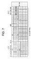
- FIG. 7 shows an allocation of section overhead bytes in a subsequent-channel STS-12 signal in the present embodiment.
- the STS-12 frame is taken as a basic SDH frame structure.
- the number of the stuffing bytes added for each of the low-speed SDH signals (STS-12) is set to 1 byte per frame.
- the number of the stuffing bytes added for each of the low-speed SDH signals (STS-48) is set to 4 bytes per frame.
- the allocations of the section overhead bytes shown in FIG. 6 and FIG. 7 are based on the basic SDH frame structure of the STS-12 frame.
- the stuffing bytes h1, h2 and h3 are allocated at the 34th, 35th and 36th columns in the section overhead of the STS-12 frame, the positions of which correspond to the positions of the SDCC bytes (D1, D2 and D3 indicated in FIG. 5A) of the section overhead of the conventional SONET frame.
- the basic regenerator SOH bytes such as B1, E1 or F1 are allocated.
- most of the basic regenerator SOH bytes are omitted except the regenerator SOH bytes A1 and A2.
- FIG. 8A and FIG. 8B show a normal pointer value setting of the conventional SONET system and a pointer value setting of the transparent-transport SONET system of the present embodiment.
- the normal pointer value setting of FIG. 8A is given for the purpose of comparison with the pointer value setting of the present embodiment.
- the pointer in the STS-1 frame consists of 10 bits and the pointer value ranges from 0 to 782 according to the normal pointer value setting.
- the initial pointer value is equal to 522.
- the pointer action byte is the H3 byte in the AU pointer bytes of the STS-1 frame.
- the pointer value 0 indicates the start of the STS-1 frame which is located following the position of the H3 byte.
- the pointer in the STS-12 frame consists of 14 bits and the pointer value ranges from 0 to 9611.
- the initial pointer value is equal to 7524.
- the pointer action byte is the h3 byte in the multiplex SOH bytes of the STS-12 frame.
- the pointer value 0 indicates the start of the STS-12 frame which is located following the position of the h3 byte (the pointer action byte).
- 14 bits out of 16 bits of the h1 and h2 bytes in the multiplex SOH of the STS-12 frame are allocated to represent the pointer value. Further, according to the pointer value setting of the transparent-transport SONET system of the present embodiment, the remaining 2 bits of the h1 and h2 bytes in the multiplex SOH of the STS-12 frame are allocated to indicate whether the correct pointer value is input to the multiplex SOH of the STS-12 frame.
- FIG. 9 shows a pointer value checking of the transparent-transport SONET system of the present embodiment.
- the two most-significant bits (MSB) in the h1 and h2 bytes in the multiplex SOH of the STS-12 frame are used for the purpose of pointer value checking. These bits are called the pointer value checking (PVC) bits.
- PVC pointer value checking
- the transparent-transport SONET system of the present embodiment can make a determination as to whether the correct pointer value is input to the h1 and h2 bytes (the pointer) of the multiplex SOH of the high-speed SDH frame, by detecting the PVC bits in the multiplex SOH of the high-speed SDH frame.
- the undefined bytes are initially set to all "0"
- the undefined bytes are initially set to all "1"
- the 2.4-Gbps low-speed SDH signals of four channels are mapped into the 10-Gbps high-speed SDH frame.
- all of the low-speed SDH signals of the four channels are not transported in a transparent manner.
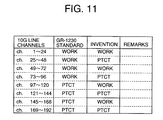
- a simple demultiplexing of the 10-Gbps SDH signal creates four groups of low-speed SDH signals: first channels 1-48; second channels 49-96; third channels 97-144; and fourth channels 145-192.
- this allocation of channels is not in conformity with that of an existing optical transmission ring network.
- FIG. 10 shows an allocation of working and protection channels in an optical-fiber cable of an optical transmission ring network.
- the ring network of FIG. 10 is 2F-BLSR (2 fiber bidirectional line switched ring) provided in GR-1230-CORE, Issue 3, December 1996.
- the allocation of channels is made according to the GR-1230 standard in such a manner that the channels 1-96 are the working channels (WORK) while the channels 97-192 are the protection channels (PTCT). Therefore, the allocation of channels made by the simple demultiplexing of the high-speed SDH frame is not in conformity with the allocation of channels defined by the ring network of FIG. 10.
- the transparent-transport SONET system of the present embodiment utilizes a modified allocation of channels which is made based on the allocation defined by the GR-1230 ring network shown in FIG. 10.
- FIG. 11 shows a modified allocation of working and protection channels in an optical-fiber cable of the transparent-transport SONET system of the present embodiment.
- the 192 channels are divided into eight 24-channel groups.
- the modified allocation of channels is made according to the present embodiment in such a manner that the channels 1-24, 49-72, 97-120, and 145-168 are the working channels (WORK) while the channels 25-48, 73-96, 121-144, and 169-192 are the protection channels (PTCT).
- WORK working channels
- PTCT protection channels
- the SDH signals of the 192 channels are transported on a signal optical-fiber cable, and the failure recovery capability of the transparent-transport SONET system of the present embodiment is not influenced. Further, any combination of the channel allocation made by the simple demultiplexing, the channel allocation defined by the ring network of FIG. 10, and the modified channel allocation can be made so as to suit the practical network applications.
Landscapes
- Engineering & Computer Science (AREA)
- Computer Networks & Wireless Communication (AREA)
- Signal Processing (AREA)
- Time-Division Multiplex Systems (AREA)
- Synchronisation In Digital Transmission Systems (AREA)
Applications Claiming Priority (2)
| Application Number | Priority Date | Filing Date | Title |
|---|---|---|---|
| JP11073627A JP2000269912A (ja) | 1999-03-18 | 1999-03-18 | 高速sdh信号による低速sdh信号の伝送方法と伝送装置 |
| JP7362799 | 1999-03-18 |
Publications (2)
| Publication Number | Publication Date |
|---|---|
| EP1037421A2 true EP1037421A2 (fr) | 2000-09-20 |
| EP1037421A3 EP1037421A3 (fr) | 2002-10-16 |
Family
ID=13523754
Family Applications (1)
| Application Number | Title | Priority Date | Filing Date |
|---|---|---|---|
| EP99309423A Withdrawn EP1037421A3 (fr) | 1999-03-18 | 1999-11-25 | Procédé et dispositif de transmission de signaux SDH à bas débit utilisant une trame SDH à haut débit |
Country Status (4)
| Country | Link |
|---|---|
| US (1) | US6674771B1 (fr) |
| EP (1) | EP1037421A3 (fr) |
| JP (1) | JP2000269912A (fr) |
| CN (1) | CN1267164A (fr) |
Cited By (2)
| Publication number | Priority date | Publication date | Assignee | Title |
|---|---|---|---|---|
| DE10204618B4 (de) * | 2001-08-09 | 2004-12-23 | Siemens Ag | Verfahren und Anordnung zur Übertragung von Qualitätskriterien einer synchronen Netzhierarchie |
| US7577147B2 (en) | 2002-09-23 | 2009-08-18 | Huawei Technologies Co., Ltd. | Transparent transmission method for administrative information of optical synchronous digital hierarchy devices of multi-vendors |
Families Citing this family (20)
| Publication number | Priority date | Publication date | Assignee | Title |
|---|---|---|---|---|
| US6657969B1 (en) | 1999-06-29 | 2003-12-02 | Cisco Technology, Inc. | Generation of synchronous transport signal data used for network protection operation |
| US6614785B1 (en) | 2000-01-05 | 2003-09-02 | Cisco Technology, Inc. | Automatic propagation of circuit information in a communications network |
| US7573915B1 (en) * | 2000-04-25 | 2009-08-11 | Cisco Technology, Inc. | Method and apparatus for transporting network management information in a telecommunications network |
| US7173936B1 (en) * | 2000-09-11 | 2007-02-06 | Ciena Corporation | Method and apparatus for partitioning SONET frames into logical channels to optimize bandwidth utilization |
| US6738392B1 (en) * | 2000-09-27 | 2004-05-18 | Cisco Technology, Inc. | Method and apparatus of framing high-speed signals |
| US20020103926A1 (en) * | 2000-12-19 | 2002-08-01 | Alcatel Usa Sourcing, L.P. | Method of transparently transporting sonet STS-3C frame information across a network |
| US7180913B2 (en) * | 2001-07-25 | 2007-02-20 | Nortel Networks Limited | Transparent error count transfer method and apparatus |
| US7023942B1 (en) * | 2001-10-09 | 2006-04-04 | Nortel Networks Limited | Method and apparatus for digital data synchronization |
| US6917759B2 (en) * | 2002-01-31 | 2005-07-12 | Nortel Networks Limited | Shared mesh signaling algorithm and apparatus |
| US20030174739A1 (en) * | 2002-03-12 | 2003-09-18 | Gagnon Ronald J. | Termination equipment with an overhead processor programmable to pass through proprietary usage data in selected overhead data slots |
| CN100358274C (zh) * | 2002-10-11 | 2007-12-26 | 华为技术有限公司 | 基于波分复用的同步网定时信号传送方法 |
| WO2004088889A1 (fr) * | 2003-03-31 | 2004-10-14 | Fujitsu Limited | Procédé et dispositif de multiplexage transparent |
| CN100373847C (zh) | 2004-12-14 | 2008-03-05 | 华为技术有限公司 | 在光传送网中传输低速率业务信号的方法 |
| CN101079676B (zh) * | 2006-05-25 | 2011-01-19 | 中兴通讯股份有限公司 | 一种光同步数字传输网络系统升级方法 |
| US7792132B2 (en) * | 2008-12-10 | 2010-09-07 | Agere Systems Inc. | Framer/mapper/multiplexor device with 1+1 and equipment protection |
| CN101626279B (zh) * | 2009-07-30 | 2013-04-17 | 北京星网锐捷网络技术有限公司 | 一种提升线路传输带宽的方法、装置和网络设备 |
| CN102652407A (zh) * | 2009-12-18 | 2012-08-29 | 日本电气株式会社 | 传输系统、发送装置、接收装置、传输方法以及计算机程序 |
| JP5659910B2 (ja) * | 2011-03-29 | 2015-01-28 | 富士通株式会社 | フレームマッピング装置及びフレームマッピング方法 |
| JP6020235B2 (ja) * | 2013-02-14 | 2016-11-02 | 富士通株式会社 | 伝送方法、伝送装置、および伝送システム |
| CN106301651A (zh) * | 2016-08-09 | 2017-01-04 | 邦彦技术股份有限公司 | 数据传输方法和装置 |
Family Cites Families (8)
| Publication number | Priority date | Publication date | Assignee | Title |
|---|---|---|---|---|
| DE4018687A1 (de) * | 1989-07-18 | 1991-01-31 | Siemens Ag | Verfahren und anordnung zur uebertragung eines blocks aus vier verwaltungseinheiten au-31 oder aus drei verwaltungseinheiten au-32 in einem synchronen transport-modul stm-1 |
| KR0160668B1 (ko) | 1994-12-30 | 1999-01-15 | 김광호 | 영상압축 비트스트림의 스타트코드 검출장치 |
| US5727036A (en) | 1995-11-22 | 1998-03-10 | Mitsubishi Semiconductor America, Inc. | High bit rate start code searching and detecting circuit and method |
| JP3663253B2 (ja) * | 1996-05-31 | 2005-06-22 | 株式会社日立コミュニケーションテクノロジー | 多重化伝送装置 |
| US6298038B1 (en) * | 1997-04-24 | 2001-10-02 | Nortel Networks Limited | Transparent transport |
| US5841760A (en) * | 1997-04-24 | 1998-11-24 | Northern Telecom Limited | Transparent multiplexer/demultiplexer |
| JPH10313332A (ja) * | 1997-05-12 | 1998-11-24 | Fujitsu Ltd | 伝送装置及びこの伝送装置を具備するネットワーク |
| IT1301719B1 (it) * | 1998-06-16 | 2000-07-07 | Alsthom Cge Alkatel | Metodo e dispositivo per migliorare la flessibilita' e la trasparenzanel trasporto delle trame ad alta velocita' nei nodi di una rete a |
-
1999
- 1999-03-18 JP JP11073627A patent/JP2000269912A/ja not_active Withdrawn
- 1999-11-25 EP EP99309423A patent/EP1037421A3/fr not_active Withdrawn
- 1999-11-29 US US09/450,062 patent/US6674771B1/en not_active Expired - Fee Related
- 1999-12-15 CN CN99126173.9A patent/CN1267164A/zh active Pending
Cited By (2)
| Publication number | Priority date | Publication date | Assignee | Title |
|---|---|---|---|---|
| DE10204618B4 (de) * | 2001-08-09 | 2004-12-23 | Siemens Ag | Verfahren und Anordnung zur Übertragung von Qualitätskriterien einer synchronen Netzhierarchie |
| US7577147B2 (en) | 2002-09-23 | 2009-08-18 | Huawei Technologies Co., Ltd. | Transparent transmission method for administrative information of optical synchronous digital hierarchy devices of multi-vendors |
Also Published As
| Publication number | Publication date |
|---|---|
| EP1037421A3 (fr) | 2002-10-16 |
| CN1267164A (zh) | 2000-09-20 |
| JP2000269912A (ja) | 2000-09-29 |
| US6674771B1 (en) | 2004-01-06 |
Similar Documents
| Publication | Publication Date | Title |
|---|---|---|
| US6674771B1 (en) | Transmission method and apparatus for transmitting low-speed SDH signals using a high-speed SDH frame | |
| US7822022B2 (en) | Multi-rate, multi-protocol, multi-port line interface for a multiservice switching platform | |
| US7957429B2 (en) | Transmission system | |
| US5490142A (en) | VT group optical extension interface and VT group optical extension format method | |
| US7085293B2 (en) | Scaleable transport of TDM channels in a synchronous frame | |
| US6891862B1 (en) | Multiplex hierarchy for high capacity transport systems | |
| JP4485348B2 (ja) | Lanサービスユニット帯域を増やすシステム及び装置 | |
| EP1396105B1 (fr) | Dispositif et procede de mappeur/trameur de canaux sdh/sonet permettant de combiner plusieurs canaux a basse vitesse en un unique canal a haute vitesse | |
| US7324563B2 (en) | Method and apparatus for transporting a SDH/SONET client signal as a service | |
| CN101150879A (zh) | 基于光传送网的交叉调度系统和方法 | |
| JPWO2001031819A1 (ja) | 伝送システム | |
| US6819686B1 (en) | Backplane protocol | |
| US6717953B1 (en) | Method of and facility for converting a SONET signal to an SDH signal | |
| CN101167281B (zh) | 用于同步交换光传输网络信号的方法和设备 | |
| US7526197B2 (en) | Utilizing the protecting bandwidth in a SONET network | |
| US5790557A (en) | Apparatus for implementing the function of a virtual container-11 and a tributary unit group-2 in a synchronous digital hierarchy | |
| US6901082B1 (en) | Method and apparatus for communicating information | |
| KR100342248B1 (ko) | 시분할 다중화를 이용하여 상이한 전송속도의 종속신호를혼합 수용하는 파장분할 다중화 시스템 | |
| KR100237475B1 (ko) | 동기식 전송시스템에서 대국 고속다중화 유니트 절체요구장치 | |
| Autry | 3.4 SONET and SDH | |
| KR100399413B1 (ko) | 동기식 디지털 계위 전송 시스템의 고계위 신호 연결 장치 | |
| Dutta et al. | Grooming mechanisms in SONET/SDH and next-generation SONET/SDH | |
| CA2289897A1 (fr) | Hierarchie multiplex pour systeme de transport a grande capacite | |
| KR19980015808A (ko) | 동기식 다중화장치에서 vc1 자국 루프백회로 |
Legal Events
| Date | Code | Title | Description |
|---|---|---|---|
| PUAI | Public reference made under article 153(3) epc to a published international application that has entered the european phase |
Free format text: ORIGINAL CODE: 0009012 |
|
| AK | Designated contracting states |
Kind code of ref document: A2 Designated state(s): AT BE CH CY DE DK ES FI FR GB GR IE IT LI LU MC NL PT SE |
|
| AX | Request for extension of the european patent |
Free format text: AL;LT;LV;MK;RO;SI |
|
| PUAL | Search report despatched |
Free format text: ORIGINAL CODE: 0009013 |
|
| AK | Designated contracting states |
Kind code of ref document: A3 Designated state(s): AT BE CH CY DE DK ES FI FR GB GR IE IT LI LU MC NL PT SE |
|
| AX | Request for extension of the european patent |
Free format text: AL;LT;LV;MK;RO;SI |
|
| 17P | Request for examination filed |
Effective date: 20030312 |
|
| AKX | Designation fees paid |
Designated state(s): FR GB |
|
| REG | Reference to a national code |
Ref country code: DE Ref legal event code: 8566 |
|
| 17Q | First examination report despatched |
Effective date: 20031110 |
|
| STAA | Information on the status of an ep patent application or granted ep patent |
Free format text: STATUS: THE APPLICATION IS DEEMED TO BE WITHDRAWN |
|
| 18D | Application deemed to be withdrawn |
Effective date: 20040323 |