EP1037708B1 - Poste de chargement pour systeme robotique - Google Patents
Poste de chargement pour systeme robotique Download PDFInfo
- Publication number
- EP1037708B1 EP1037708B1 EP98959120A EP98959120A EP1037708B1 EP 1037708 B1 EP1037708 B1 EP 1037708B1 EP 98959120 A EP98959120 A EP 98959120A EP 98959120 A EP98959120 A EP 98959120A EP 1037708 B1 EP1037708 B1 EP 1037708B1
- Authority
- EP
- European Patent Office
- Prior art keywords
- data signal
- items
- item
- robotic system
- rack
- Prior art date
- Legal status (The legal status is an assumption and is not a legal conclusion. Google has not performed a legal analysis and makes no representation as to the accuracy of the status listed.)
- Expired - Lifetime
Links
- 238000000034 method Methods 0.000 claims description 10
- 239000003153 chemical reaction reagent Substances 0.000 claims description 8
- 230000003213 activating effect Effects 0.000 claims 1
- 238000003556 assay Methods 0.000 description 1
- 238000010923 batch production Methods 0.000 description 1
- 230000005540 biological transmission Effects 0.000 description 1
- 238000013500 data storage Methods 0.000 description 1
- 230000000994 depressogenic effect Effects 0.000 description 1
- 238000009826 distribution Methods 0.000 description 1
- 230000001939 inductive effect Effects 0.000 description 1
- 239000007788 liquid Substances 0.000 description 1
- 238000003754 machining Methods 0.000 description 1
- 238000003860 storage Methods 0.000 description 1
- 239000000126 substance Substances 0.000 description 1
- 239000000758 substrate Substances 0.000 description 1
Images


Classifications
-
- B—PERFORMING OPERATIONS; TRANSPORTING
- B01—PHYSICAL OR CHEMICAL PROCESSES OR APPARATUS IN GENERAL
- B01L—CHEMICAL OR PHYSICAL LABORATORY APPARATUS FOR GENERAL USE
- B01L3/00—Containers or dishes for laboratory use, e.g. laboratory glassware; Droppers
- B01L3/54—Labware with identification means
- B01L3/545—Labware with identification means for laboratory containers
- B01L3/5453—Labware with identification means for laboratory containers for test tubes
-
- B—PERFORMING OPERATIONS; TRANSPORTING
- B01—PHYSICAL OR CHEMICAL PROCESSES OR APPARATUS IN GENERAL
- B01L—CHEMICAL OR PHYSICAL LABORATORY APPARATUS FOR GENERAL USE
- B01L9/00—Supporting devices; Holding devices
- B01L9/56—Means for indicating position of a recipient or sample in an array
-
- G—PHYSICS
- G01—MEASURING; TESTING
- G01N—INVESTIGATING OR ANALYSING MATERIALS BY DETERMINING THEIR CHEMICAL OR PHYSICAL PROPERTIES
- G01N35/00—Automatic analysis not limited to methods or materials provided for in any single one of groups G01N1/00 - G01N33/00; Handling materials therefor
- G01N35/00584—Control arrangements for automatic analysers
- G01N35/00722—Communications; Identification
- G01N35/00732—Identification of carriers, materials or components in automatic analysers
- G01N2035/00742—Type of codes
- G01N2035/00752—Type of codes bar codes
Definitions
- the present invention is generally in the field of robotics and concerns a method and system for loading items to a robotic system to allow the robotic system to identify and locate each of the items.
- the present invention further relates to item holding racks, adapted to cooperate with such a system and which may be used to transfer the items to the robotic system.
- Robotic systems are generally adapted to handle and manipulate items for various purposes. Specific examples are various robotic systems used in medical diagnostics in which specimens are handled, processed and then analyzed automatically to eventually generate a diagnostic report. Such diagnostic systems are typically adapted to handle simultaneously a plurality of specimens and furthermore employ a large number of reagents for the different chemical, biochemical or biological tests conducted within the system.
- the reagents typically liquids, are held in containers which are placed in designated receptacles. If the operator mistakenly places a reagent in an incorrect receptacle, the entire task of the system may be incorrectly performed.
- the document US-A-4 678 894 describes a loading station having a sensing panel with IR-detectors.
- the present invention provides a loading station for loading items to a robotic system such that each of the items will be identified and located, the station comprising:
- the present invention provides a method for loading items to a robotic system, such that each of the items will be identified and located by the system, the method comprising:
- the method of the invention is typically concerned with a batch process wherein a batch of items is placed on the panel of the loading station and then the processor generates an output data signal allowing the robotic system to identify each of the items in the batch.
- the loading station is intended for loading specimens and/or reagents to a diagnostic robotic system for simultaneous handling and performing one or more diagnostic assays on a plurality of biological specimens.
- the tray by one embodiment, is a flat panel, with each of the items, having a flat bottom surface, placed directly thereon.
- the panel has integral receptacles adapted to receive the items, each such receptacle being fitted with a sensor.
- the panel has an array of pressure sensors, each one at a different location, actuatable by an item placed on the tray at this location.
- the loading station is located adjacent or within the robotic system, and the manipulating head or arm of the robot grabs the items directly from the station.
- the items may be loaded on racks which are adapted to cooperate with the loading station and the items are then transported to the robotic system within such racks.
- the racks are placed on the sensing panel and the racks being designed such that placing of an item in the rack actuates the sensing panel to generate a location data signal.
- Such a rack has a plurality of receptacles, each adapted to receive one of the items, and when placed on the panel, once an item is placed in the receptacle, the sensor on the panel is actuated.
- Each receptacle of the rack is fitted at its bottom face with a mediating actuating member, movable in a vertical direction; once the item is placed in the receptacle, it presses the member which in turn presses the sensor on the panel.
- the rack has an identifier tag readable by a reader unit both in the loading station and in the robotic system and the output data signal contains also information bits identifying the particular racks.
- a rack adapted for use with a loading station of the invention according to claim 9, is novel and constitutes an independent aspect of the invention.
- Such a rack has typically a full proof positioning arrangement, e.g. a dedicated shape, positioning pins or notches, etc., so as to ensure accurate placement thereof on the panel.
- the reading assembly may typically comprise a bar-code reader, with the signs allocated to each item being accordingly bar-codes.
- the bar-code may be applied on a sticker attached to the item or may be placed on a separate substrate, e.g. sheet or board, in a manner allowing to associate it with the item.
- the bar-code reader then scans the bar-code prior to placing the item on the panel.
- the bar-code reader may be a manually held reader, it may be a fixed reader on which the item is placed or passed by so that the bar-code typically on a sticker thereof, can be read, etc.
- the output data signal may be transferred to the robotic system in line by data transfer lines, or may be transferred on a transferable storage media, e.g. a data storage disk or tape, or by transmission, etc.
- a transferable storage media e.g. a data storage disk or tape, or by transmission, etc.
- the specific embodiment illustrated herein refers to a station for loading vials, reagent vessels, etc., into a robotic system where specimens are automatically diagnosed.
- the invention should not be construed as being limited only to this embodiment, and applies, mutatis mutandis , also to loading stations of other types of items which are to be loaded into a robotic system. Examples are machining tools, robots of assembly lines, etc.
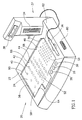
- Fig. 1 shows a loading station 20 having a base structure 22, holding a sensing panel 24, slightly depressed below the open surface of the base structure, and user operable push buttons 26, 28 and 30.
- the loading station further comprises a reading assembly generally designated 32 comprising a stationary bar-code reader 34, a manually held, pencil-like bar-code reader 36 and an LCD display 38.
- Panel 24 has a plurality of pressure sensors of different dimensions and spatial distribution 40, 42, 44 and 46, each emitting a data signal once pressure is applied thereon, indicative of its location.
- Panel 24 has three rack-receiving zones 50, 52 and 54 and has circumferential edges 58, 60, 62 and 64.
- Zone 50 of panel 24 is defined by edge 58, the respective portions of edges 60 and 64 and by a triangular projection 66;
- zone 52 is defined by respective portions of edges 60 and 64 and by triangular projections 66 and 68;
- zone 54 is defined by edge 62, the respective portions of edges 60 and 64 and triangular projection 68.
- the corner 70 of zone 54 is truncated.
- zones 50 and 54 differ from zone 52 by their overall dimension, they are distinguished from one another by the existence of the truncated corner 70 in zone 54.
- a rack which will be designed to fit in one zone cannot be misplaced in another zone.
- the station further comprises a data port 80, for connection to the robotic system or for connection to remote data system, e.g. for receiving information associating each bar-code to an item.
- Push buttons 24, 28 and 30 are usable for various manual functions including on / off , cancel a last input, general reset, etc.
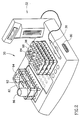
- Fig. 2 shows the station 20 fitted with two racks 82 and 84, the former holding a reagent vessel 86 and the latter a plurality of specimen vials 88.
- Receptacles 92 and 94 of rack 82, and each of receptacles 96 of rack 84, are placed such that each corresponds to one of respective pressure sensors 40, 42,44 or 46, respectively, and thus once a vessel or a vial is placed into a receptacle, a respective pressure sensor below is actuated.
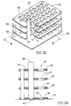
- FIG. 3 Two different embodiments of racks for use with the loading station of the invention, are shown in Figs. 3 and 4.
- the rack shown in Fig. 3, is rack 84 which is shown in Fig. 2, but designed so as to fit specifically into zone 54, with the various receptacles 96 being each above one of the pressure sensors 46, as can be seen specifically in Fig. 3B.
- Each of receptacles 96 is defined by aligned openings, consisting of three openings 97 in the racks' upper and two intermediate horizontal boards 98, which have a diameter corresponding to the external diameter of vial 88, and an opening 97' at bottom board 98', which has a diameter such that it allows only the tip of the curved bottom end of vial 88 to protrude therethrough.
- the opening is sufficiently small so as to support the vial 88, but on the other hand allows the bottom end to actuate pressure sensor 46, as can specifically be seen in Fig. 3B.
- Rack 100 which can be seen in Fig. 4, is designed to fit into zone 52.
- This rack has a plurality of bores 102 each being a receptacle adapted to receive a vial 104, and each fitted with a movable actuating member 106 at its bottom.
- Actuating member 106 has a tapered bottom end 108 for actuating the pressure sensor 46 (Fig. 4B).
- a rack in accordance with the embodiment shown in Fig. 3 can be used for vials or other vessels having a concave bottom and thereby can directly actuate the pressure sensor.
- the rack of the kind shown in Fig. 4 is useful in cases where the vessel or the vial has a flat bottom whereby the actuating member serves to focus the pressure onto the pressure sensor.
- a tag 120 is prepared, typically a bar-code, which identifies a specific vessel.
- the tag 120 may then be fixed on to a vessel 122 which in the specific example is a vial, (Fig. 5B), and then the vessel 122 is brought to the loading station where the sticker is read by an appropriate reading unit, e.g. a manual pen-like bar-code reading unit 124 which reads the bar-code on tag 120 (Fig. 5c).
- an appropriate reading unit e.g. a manual pen-like bar-code reading unit 124 which reads the bar-code on tag 120 (Fig. 5c).
- the vessel 122 is placed into a receptacle 126 of a rack 128 (of which only a small section is shown) which then actuates the pressure sensor 130 on the sensing pad 132.
- the rack has typically a readable identifiable tag which identifies the rack once it is transferred to the robotic system with its load of vials or vessels.
- the identified tag may, for example, be an array of small magnets and the reader an array of ball sensors. The pattern of the magents thus identifies the racks.
- the loading station generates an output data signal, which provides information on identity (established in the steps shown in Fig. 5C) and location (established in the steps shown in Fig. 5D) to provide to the robotic system an identity/location data for each of the different items.
Landscapes
- Chemical & Material Sciences (AREA)
- Health & Medical Sciences (AREA)
- Clinical Laboratory Science (AREA)
- Chemical Kinetics & Catalysis (AREA)
- Analytical Chemistry (AREA)
- Automatic Analysis And Handling Materials Therefor (AREA)
Abstract
Claims (9)
- Poste de chargement (20) pour le chargement d'articles sur un système robotique de sorte que chacun des articles sera identifié et localisé, le poste comprenant :un panneau (24) de détection sensible à la pression sur lequel les articles sont placés et qui possède un agencement de détection pour émettre un signal de donnée d'emplacement sensible au positionnement d'un article sur sa surface, et étant indicatif du positionnement de l'article sur un plateau ;un dispositif de lecture (32) pour lire un repère attribué à chaque article différent avant son positionnement sur le plateau et l'émission d'un signal de donnée d'identité correspondant audit repère ; etun processeur pour recevoir ledit signal de donnée d'emplacement et ledit signal de donnée d'identité, attribuant l'un à l'autre, et générant un signal de donnée de sortie à transférer au système robotique.
- Poste de chargement selon la revendication 1, dans lequel le panneau (24) sensible à la pression comporte une rangée de capteurs de pression (40, 42, 44, 46), chacun à un emplacement différent, activable par un article placé sur le plateau à cet emplacement.
- Poste de chargement selon la revendication 1 ou 2, conçu pour coopérer avec un casier, comportant une pluralité de compartiments, chacun conçu pour recevoir l'un des articles, les casiers étant conçus de sorte que le positionnement d'un article dans celui-ci active le panneau de détection pour induire un signal de donnée d'attribution.
- Poste de chargement selon la revendication 3, dans lequel les articles sont transportés vers un système robotique à l'intérieur dudit casier.
- Poste de chargement selon l'une quelconque des revendications 1 à 4, comportant une unité de lecture conçue pour lire un repère d'identification fixée sur ledit casier et le signal de donnée de sortie généré par le poste permet au système robotique d'identifier le casier par un tel repère associé au casier.
- Procédé de chargement d'article dans un système robotique, tel que chacun des articles sera identifié et localisé par le système, le procédé comprenant :(a) la génération d'un repère d'identification d'article lisible à associer avec chaque article ;(b) la lecture du repère d'un article par un dispositif de lecture de repère approprié pour générer un signal de donnée d'identité correspondant audit repère et, par la suite, le positionnement de l'article sur un panneau d'un poste de chargement comportant un panneau de pression pour identifier le positionnement et pour émettre un signal de donnée d'emplacement indicatif du positionnement dudit article sur le plateau ; et(d) au moyen d'un processeur, la réception et la mise en concordance du signal de donnée d'identité et du signal de donnée d'emplacement pour chacun des articles, afin de générer un signal de donnée de sortie pour transfert audit système robotique, de manière à permettre au système robotique de situer chacun des articles.
- Procédé selon la revendication 6, comprenant le positionnement d'un lot d'articles unique sur le panneau de détection, puis la génération d'un signal de donnée de sortie pour le lot entier.
- Procédé selon la revendication 7, destiné au chargement d'échantillons, de réactifs ou des deux, dans un système de diagnostic robotique.
- Casier pour chargement d'article dans un système robotique, conçu pour coopération avec un poste de chargement, selon l'une quelconque des revendications 3 à 5, dans lequel le casier comporte une pluralité d'alésages de compartiment, chaque alésage ajusté au niveau de l'extrémité de partie de fond de celui-ci avec un élément d'active ment mobile pour activer un panneau de détection du poste de chargement, où ledit élément d'active ment est déplacé de manière sensible au positionnement d'un article dans l'alésage correspondant.
Applications Claiming Priority (3)
| Application Number | Priority Date | Filing Date | Title |
|---|---|---|---|
| IL12258197 | 1997-12-12 | ||
| IL12258197A IL122581A (en) | 1997-12-12 | 1997-12-12 | Loading station for loading items to a robotic system |
| PCT/IL1998/000594 WO1999030824A1 (fr) | 1997-12-12 | 1998-12-07 | Poste de chargement pour systeme robotique |
Publications (2)
| Publication Number | Publication Date |
|---|---|
| EP1037708A1 EP1037708A1 (fr) | 2000-09-27 |
| EP1037708B1 true EP1037708B1 (fr) | 2002-09-11 |
Family
ID=11070967
Family Applications (1)
| Application Number | Title | Priority Date | Filing Date |
|---|---|---|---|
| EP98959120A Expired - Lifetime EP1037708B1 (fr) | 1997-12-12 | 1998-12-07 | Poste de chargement pour systeme robotique |
Country Status (5)
| Country | Link |
|---|---|
| EP (1) | EP1037708B1 (fr) |
| AU (1) | AU1503399A (fr) |
| DE (1) | DE69807931T2 (fr) |
| IL (1) | IL122581A (fr) |
| WO (1) | WO1999030824A1 (fr) |
Families Citing this family (12)
| Publication number | Priority date | Publication date | Assignee | Title |
|---|---|---|---|---|
| EP1733239B1 (fr) * | 2004-04-07 | 2011-11-16 | Tecan Trading AG | Dispositif et procede d'identification, de localisation et de poursuite d'objets situes sur des equipements de laboratoire |
| US7278328B2 (en) * | 2004-09-03 | 2007-10-09 | Protedyne Corporation | Method and apparatus for handling sample holders |
| FR2892821B1 (fr) * | 2005-11-02 | 2008-02-01 | Concept Pro Sarl | Dispositif integre et/ou automatise pour le reperage et/ou la tracabilite de recipients d'echantillonnage de prelevements primaires medicaux ou veterinaires |
| US7688207B2 (en) * | 2006-07-28 | 2010-03-30 | Abbott Laboratories Inc. | System for tracking vessels in automated laboratory analyzers by radio frequency identification |
| PT104498A (pt) * | 2009-04-09 | 2010-10-11 | Isens Electronica Lda | Sistema de armazenamento com associação de indicador visual e sensor de presença |
| BE1018828A3 (nl) * | 2009-07-16 | 2011-09-06 | Praet Peter Van | Intelligent rek voor specimen buisjes en werkwijze om de buisjes in het rek te laden. |
| US20140273268A1 (en) * | 2011-10-12 | 2014-09-18 | Eprep Pty Ltd. | Preparation of samples for analysis |
| EP2810068B1 (fr) * | 2012-02-03 | 2017-04-19 | Siemens Healthcare Diagnostics Inc. | Porte-échantillon affichant un état |
| EP2724778B1 (fr) * | 2012-10-24 | 2017-08-09 | F. Hoffmann-La Roche AG | Système et procédé permettant de localiser des récipients d'échantillonnage |
| DE112016003593T5 (de) | 2015-08-06 | 2018-05-30 | Elemental Scientific, Inc. | Autosampler-Proben- und Probengestell-Identifizierung |
| ES2748186A1 (es) * | 2018-09-13 | 2020-03-13 | Menarini Diagnosticos S A | Metodo y sistema para gestionar el almacenamiento de objetos basado en doble etiquetado |
| CN110201738B (zh) * | 2019-07-09 | 2024-05-17 | 四川大学华西医院 | 用于批量信息采集的标本架及标本信息采集系统和方法 |
Family Cites Families (5)
| Publication number | Priority date | Publication date | Assignee | Title |
|---|---|---|---|---|
| US4353552A (en) * | 1979-02-23 | 1982-10-12 | Peptek, Incorporated | Touch panel system and method |
| US4678894A (en) * | 1985-04-18 | 1987-07-07 | Baxter Travenol Laboratories, Inc. | Sample identification system |
| EP0258565A3 (fr) * | 1986-07-02 | 1989-05-24 | E.I. Du Pont De Nemours And Company | Moyen pour l'identification de la position |
| US5777303A (en) * | 1994-09-09 | 1998-07-07 | Gay Freres, Vente Et Exportation S.A. | Device for associating test tube samples with electronic labels for storage of identifying data |
| US5700429A (en) * | 1995-04-19 | 1997-12-23 | Roche Diagnostic Systems, Inc. | Vessel holder for automated analyzer |
-
1997
- 1997-12-12 IL IL12258197A patent/IL122581A/en active IP Right Grant
-
1998
- 1998-12-07 EP EP98959120A patent/EP1037708B1/fr not_active Expired - Lifetime
- 1998-12-07 DE DE69807931T patent/DE69807931T2/de not_active Expired - Fee Related
- 1998-12-07 WO PCT/IL1998/000594 patent/WO1999030824A1/fr not_active Ceased
- 1998-12-07 AU AU15033/99A patent/AU1503399A/en not_active Abandoned
Also Published As
| Publication number | Publication date |
|---|---|
| IL122581A0 (en) | 1998-06-15 |
| DE69807931T2 (de) | 2003-05-15 |
| WO1999030824A1 (fr) | 1999-06-24 |
| IL122581A (en) | 2001-05-20 |
| EP1037708A1 (fr) | 2000-09-27 |
| AU1503399A (en) | 1999-07-05 |
| DE69807931D1 (de) | 2002-10-17 |
Similar Documents
| Publication | Publication Date | Title |
|---|---|---|
| JP7846643B2 (ja) | 検査室システム | |
| US5460057A (en) | Method and apparatus for handling samples and sample collection system | |
| EP2959432B1 (fr) | Détection d'orientation d'étagère à multiples étiquettes | |
| US7278328B2 (en) | Method and apparatus for handling sample holders | |
| EP1037708B1 (fr) | Poste de chargement pour systeme robotique | |
| US5663545A (en) | Labware identification system | |
| EP0510686B1 (fr) | Automate d'analyse lisant les données associées aux récipients et méthode de manipulation des réactifs dans cet automate | |
| US8034293B2 (en) | Automated diagnostic workstation | |
| EP3153865B1 (fr) | Analyseur automatique | |
| US20080042839A1 (en) | Device and Method for Identifying, Locating and Tracking Objects on Laboratory Equipment | |
| CN100523818C (zh) | 自动分析装置 | |
| US20100025464A1 (en) | Method and System to Localise and Identify Test Tubes | |
| WO2001056753A1 (fr) | Lecteur de code-barres monte sur un robot | |
| EP3626652B1 (fr) | Système de gestion de consommables pour laboratoires | |
| JPS6315164A (ja) | 生化学分析装置のテストパツク選択供給装置 | |
| JP2010502961A (ja) | 臨床サンプル容器のための同定システム | |
| US20210354123A1 (en) | Cover member with orientation indicia | |
| US8371051B2 (en) | System to label plates | |
| CN105408917A (zh) | 用于便利对象的手动分类的系统和方法 | |
| JPH0894626A (ja) | 自動分析装置 | |
| JP2001099840A (ja) | 自動分析装置 | |
| JPH03285173A (ja) | 生化学分析装置 | |
| EP0765480A1 (fr) | Analyse automatisee mettant en uvre un support en forme de peigne | |
| JPH08278311A (ja) | 血液、尿等の試料を分析する自動分析装置 |
Legal Events
| Date | Code | Title | Description |
|---|---|---|---|
| PUAI | Public reference made under article 153(3) epc to a published international application that has entered the european phase |
Free format text: ORIGINAL CODE: 0009012 |
|
| 17P | Request for examination filed |
Effective date: 20000712 |
|
| AK | Designated contracting states |
Kind code of ref document: A1 Designated state(s): DE FR GB IT |
|
| GRAG | Despatch of communication of intention to grant |
Free format text: ORIGINAL CODE: EPIDOS AGRA |
|
| RAP1 | Party data changed (applicant data changed or rights of an application transferred) |
Owner name: TREK DIAGNOSTIC SYSTEMS, LTD. |
|
| RAP1 | Party data changed (applicant data changed or rights of an application transferred) |
Owner name: TREK DIAGNOSTIC SYSTEMS, INC. Owner name: TREK DIAGNOSTIC SYSTEMS, LTD. |
|
| 17Q | First examination report despatched |
Effective date: 20011031 |
|
| GRAG | Despatch of communication of intention to grant |
Free format text: ORIGINAL CODE: EPIDOS AGRA |
|
| GRAH | Despatch of communication of intention to grant a patent |
Free format text: ORIGINAL CODE: EPIDOS IGRA |
|
| GRAH | Despatch of communication of intention to grant a patent |
Free format text: ORIGINAL CODE: EPIDOS IGRA |
|
| GRAA | (expected) grant |
Free format text: ORIGINAL CODE: 0009210 |
|
| AK | Designated contracting states |
Kind code of ref document: B1 Designated state(s): DE FR GB IT |
|
| PG25 | Lapsed in a contracting state [announced via postgrant information from national office to epo] |
Ref country code: IT Free format text: LAPSE BECAUSE OF FAILURE TO SUBMIT A TRANSLATION OF THE DESCRIPTION OR TO PAY THE FEE WITHIN THE PRE;WARNING: LAPSES OF ITALIAN PATENTS WITH EFFECTIVE DATE BEFORE 2007 MAY HAVE OCCURRED AT ANY TIME BEFORE 2007. THE CORRECT EFFECTIVE DATE MAY BE DIFFERENT FROM THE ONE RECORDED.SCRIBED TIME-LIMIT Effective date: 20020911 |
|
| REG | Reference to a national code |
Ref country code: GB Ref legal event code: FG4D |
|
| REF | Corresponds to: |
Ref document number: 69807931 Country of ref document: DE Date of ref document: 20021017 |
|
| ET | Fr: translation filed | ||
| PLBE | No opposition filed within time limit |
Free format text: ORIGINAL CODE: 0009261 |
|
| STAA | Information on the status of an ep patent application or granted ep patent |
Free format text: STATUS: NO OPPOSITION FILED WITHIN TIME LIMIT |
|
| 26N | No opposition filed |
Effective date: 20030612 |
|
| PGFP | Annual fee paid to national office [announced via postgrant information from national office to epo] |
Ref country code: GB Payment date: 20031203 Year of fee payment: 6 |
|
| PGFP | Annual fee paid to national office [announced via postgrant information from national office to epo] |
Ref country code: FR Payment date: 20031218 Year of fee payment: 6 |
|
| PGFP | Annual fee paid to national office [announced via postgrant information from national office to epo] |
Ref country code: DE Payment date: 20040202 Year of fee payment: 6 |
|
| PG25 | Lapsed in a contracting state [announced via postgrant information from national office to epo] |
Ref country code: GB Free format text: LAPSE BECAUSE OF NON-PAYMENT OF DUE FEES Effective date: 20041207 |
|
| PG25 | Lapsed in a contracting state [announced via postgrant information from national office to epo] |
Ref country code: DE Free format text: LAPSE BECAUSE OF NON-PAYMENT OF DUE FEES Effective date: 20050701 |
|
| GBPC | Gb: european patent ceased through non-payment of renewal fee |
Effective date: 20041207 |
|
| PG25 | Lapsed in a contracting state [announced via postgrant information from national office to epo] |
Ref country code: FR Free format text: LAPSE BECAUSE OF NON-PAYMENT OF DUE FEES Effective date: 20050831 |
|
| REG | Reference to a national code |
Ref country code: FR Ref legal event code: ST |