EP1037802B1 - Procédé et dispositif permettant d'embobiner des éléments allongés et flexibles en bobines fractionnelles disposées en ligne et d'emballer ces dernières à l'aide d'un film protecteur fait d'un matériau flexible, et empaquetage de bobines emballées - Google Patents
Procédé et dispositif permettant d'embobiner des éléments allongés et flexibles en bobines fractionnelles disposées en ligne et d'emballer ces dernières à l'aide d'un film protecteur fait d'un matériau flexible, et empaquetage de bobines emballées Download PDFInfo
- Publication number
- EP1037802B1 EP1037802B1 EP98945675A EP98945675A EP1037802B1 EP 1037802 B1 EP1037802 B1 EP 1037802B1 EP 98945675 A EP98945675 A EP 98945675A EP 98945675 A EP98945675 A EP 98945675A EP 1037802 B1 EP1037802 B1 EP 1037802B1
- Authority
- EP
- European Patent Office
- Prior art keywords
- drum
- guiding devices
- wrapping
- reel
- ring
- Prior art date
- Legal status (The legal status is an assumption and is not a legal conclusion. Google has not performed a legal analysis and makes no representation as to the accuracy of the status listed.)
- Expired - Lifetime
Links
- 238000000034 method Methods 0.000 title claims abstract description 23
- 230000001681 protective effect Effects 0.000 title claims abstract description 6
- 238000012856 packing Methods 0.000 title 1
- 238000004804 winding Methods 0.000 claims abstract description 18
- 230000007246 mechanism Effects 0.000 claims abstract description 13
- 239000013013 elastic material Substances 0.000 claims abstract description 4
- 238000006073 displacement reaction Methods 0.000 claims abstract 2
- 239000002985 plastic film Substances 0.000 claims description 11
- 229920006255 plastic film Polymers 0.000 claims description 11
- 238000004806 packaging method and process Methods 0.000 claims description 7
- 238000004519 manufacturing process Methods 0.000 description 5
- 230000002093 peripheral effect Effects 0.000 description 3
- 239000004033 plastic Substances 0.000 description 2
- 230000001360 synchronised effect Effects 0.000 description 2
- 238000005452 bending Methods 0.000 description 1
- 210000000078 claw Anatomy 0.000 description 1
- 239000004020 conductor Substances 0.000 description 1
- 238000005520 cutting process Methods 0.000 description 1
- 230000007613 environmental effect Effects 0.000 description 1
- 230000002349 favourable effect Effects 0.000 description 1
- 238000002347 injection Methods 0.000 description 1
- 239000007924 injection Substances 0.000 description 1
- 230000003993 interaction Effects 0.000 description 1
- 239000000243 solution Substances 0.000 description 1
- 239000012780 transparent material Substances 0.000 description 1
- 238000003466 welding Methods 0.000 description 1
Images


Classifications
-
- B—PERFORMING OPERATIONS; TRANSPORTING
- B65—CONVEYING; PACKING; STORING; HANDLING THIN OR FILAMENTARY MATERIAL
- B65B—MACHINES, APPARATUS OR DEVICES FOR, OR METHODS OF, PACKAGING ARTICLES OR MATERIALS; UNPACKING
- B65B25/00—Packaging other articles presenting special problems
- B65B25/24—Packaging annular articles, e.g. tyres
-
- B—PERFORMING OPERATIONS; TRANSPORTING
- B65—CONVEYING; PACKING; STORING; HANDLING THIN OR FILAMENTARY MATERIAL
- B65D—CONTAINERS FOR STORAGE OR TRANSPORT OF ARTICLES OR MATERIALS, e.g. BAGS, BARRELS, BOTTLES, BOXES, CANS, CARTONS, CRATES, DRUMS, JARS, TANKS, HOPPERS, FORWARDING CONTAINERS; ACCESSORIES, CLOSURES, OR FITTINGS THEREFOR; PACKAGING ELEMENTS; PACKAGES
- B65D85/00—Containers, packaging elements or packages, specially adapted for particular articles or materials
- B65D85/02—Containers, packaging elements or packages, specially adapted for particular articles or materials for annular articles
- B65D85/04—Containers, packaging elements or packages, specially adapted for particular articles or materials for annular articles for coils of wire, rope or hose
-
- B—PERFORMING OPERATIONS; TRANSPORTING
- B65—CONVEYING; PACKING; STORING; HANDLING THIN OR FILAMENTARY MATERIAL
- B65H—HANDLING THIN OR FILAMENTARY MATERIAL, e.g. SHEETS, WEBS, CABLES
- B65H54/00—Winding, coiling, or depositing filamentary material
- B65H54/02—Winding and traversing material on to reels, bobbins, tubes, or like package cores or formers
- B65H54/10—Winding and traversing material on to reels, bobbins, tubes, or like package cores or formers for making packages of specified shapes or on specified types of bobbins, tubes, cores, or formers
- B65H54/20—Winding and traversing material on to reels, bobbins, tubes, or like package cores or formers for making packages of specified shapes or on specified types of bobbins, tubes, cores, or formers forming multiple packages
-
- B—PERFORMING OPERATIONS; TRANSPORTING
- B65—CONVEYING; PACKING; STORING; HANDLING THIN OR FILAMENTARY MATERIAL
- B65H—HANDLING THIN OR FILAMENTARY MATERIAL, e.g. SHEETS, WEBS, CABLES
- B65H54/00—Winding, coiling, or depositing filamentary material
- B65H54/56—Winding of hanks or skeins
Definitions
- the present invention concerns a procedure and an arrangement for winding flexible, elongated elements onto partial reels arranged in a row and wrapping these with protecting film of elastic material.
- the invention also concerns a packaging with wrapped reels.
- a core is attached to the rotating spool-head, where the core preferably includes a drum provided with a flange on which the cable is wound and possibly, but not necessarily, provided with a protective and unifying wrapping of plastic film.
- the assembly formed by this means is thereafter pulled off the spool-head in its entirety, i.e. accompanied by the core.
- the problem of withdrawing a pre-determined length of wound cable or reeled flexible element can, for example, arise in that the user may on one occasion wish to withdraw only a part of the element whose length differs significantly from the length of the element that is wound on one continuous reel and wrapped in plastic film.
- lines that are wound on spools the solution to this problem is already known through, for example, US 2 912 102. According to this document, which does in fact refer to fishing lines, the problem is solved in that a comparatively long line with no breaks is wound on several spools arranged following one another.
- spools are subsequently arranged in a row with a coinciding centre axis and are packaged so that they are connected by being provided with a wrapping of elastic transparent material, preferably plastic film, that by elastic shrinkage tightly wraps and fixes the said spools, and thereby even the line on each one of them, in position.
- the desired length of line in the form of a chosen number of spools can then be simply removed from the package in a conventional way by the wrapping being split peripherally at a suitable place and the line being cut, whereby the plastic film tightly wrapping the spools keeps the line remaining on the respective separated spool sections.
- One objective of the present invention is therefore to achieve a procedure that makes this possible and, more specifically, allows the production of core-free "multi-reels", i.e., a number of reels arranged after one another as segments and wrapped in an elastic film.
- a second objective of the invention is to achieve an arrangement for performing this procedure, and a third objective is to achieve a packaging of an elongated flexible element wound onto partial reels and wrapped with elastic film that is designed so that by means of a peripheral sectioning of the wrapping that is common to all of the reels, a pre-determined length of the element in the form of a specified number of partial reels can be simply removed from the packaging without the removed section/sections needing to be repackaged.
- the wrapping of elastic film on every partial reel can be further improved if the partial reel that is to be provided with a wrapping is at a distance from a reel that has been provided with a wrapping in a previous step so that this partial reel does not constitute a hinder for the wrapping sequence of the partial reel that is to be provided with a wrapping.
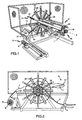
- fig. 1 shows a perspective view of an arrangement for winding flexible elongated elements onto continuous reels and wrapping these with a protective film of elastic material according to the invention
- fig. 2 shows a frontal view of the arrangement according to fig. 1
- fig. 3 shows a longitudinal view of a part of the arrangement in fig. 1 and 2 to clarify the mechanism for manoeuvring the arrangement's device for moving the wound element on the drum
- fig. 4 shows a cross-sectional view according to IIII - IIII in fig.
- fig. 5 shows a cross-sectional view according to V - V in fig. 3, fig.
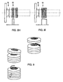
- FIG. 6 shows a longitudinal view of a device for adjusting the diameter of the drum
- fig. 7 shows a beam included in the drum in cross-section
- fig. 8A - 8I illustrate the measures taken according to the invention when it is used to wind flexible elements onto partial reels and wrap these in a cover of elastic film
- fig. 9 shows a package of the partial reels produced with the procedure according to the invention.
- the reference number 1 designates the base mounting plate or frame of the arrangement according to the invention, on which a drum 2 is attached in an overhanging, cantilever manner for rotational movement so that when operated by a driving unit in the form of an electric motor (not shown) with gearing where the number of revolutions per minute can be adjusted, it can be brought to rotate at a chosen speed around an essentially horizontal axis.
- the speed of rotation of the drum 2 is registered, for example, by a pulse transducer attached to the axis of rotation and communicated to a control unit not shown in detail on the drawings.
- a control unit not shown in detail on the drawings.
- a feeding mechanism 4 is arranged that includes a number of rollers between which an elongated element designated 5 runs prior to it being wound onto drum 2. Since the feeding mechanism 4 synchronised with the speed of rotation of the drum 2 performs a continuous forwards and return movement parallel with the main axis of the drum, the element 5 passes through feeding mechanism and is applied onto the drum 2 with overlapping, evenly spaced turns along the length of the drum.
- a unit 6 for wrapping the element 5 wound on the drum with elastic film 7, preferably in the form of plastic film, is arranged on one side of the drum.
- This unit 6 includes a rotating housing and a replaceable cylinder 8 equipped with a braking device and arranged to carry a roll of plastic film 9 that, as a consequence of the rotation of the drum and its passage over two cylinders 10, 10' , allows the film to be continuously fed out from the roll and wrapped around the element 5 wound on the drum 2.
- the unit 6 is arranged to be moveable in an axial direction so that it can travel backwards and forwards in parallel with the main axis 3 of the drum 2.
- the cylinders in a per se known manner can be designed so that the film 7 is stretched in a sideways direction as it passes over the cylinders.
- the arrangement also includes an arm 11 housed so that it can be pivoted on the frame 1 via the axis of rotation 3 of the drum 2 and arranged to perform an oscillating movement about the drum 2 in a first direction by the interaction of a piston and cylinder device (not shown in the figure) between the arm 11 and the frame 1, and a return movement in a second, opposite direction by a turning plate arranged on the pivoting axis 3 of the drum and a braking device acting on this, by means of which the arm 11, through fixed braking, is rapidly returned to its starting position by the drum (not shown in the figure).
- a piston and cylinder device not shown in the figure
- arm 11 supports a clamping device 12 that, when the arm is in its starting position as shown in fig. 1, is positioned between the two cylinders 10, 10' .
- This clamping device 12 which is not described in greater detail, is designed so that the elastic film 7 is always taken up by it.
- the said clamping device can in general be said to include a "claw" in the form of interacting arm parts of which one is housed so that it can be pivoted and its manoeuvrability affected by a piston and cylinder device (not shown in the figures).
- the task of arm 11 is to utilise the clamping device 12 to grip hold of the plastic film 7 and draw it out from the roll 9 and, by oscillating in the first direction about the drum 2, initially apply the said film to a reel wound onto the drum so that it attaches to it.
- the piston and cylinder device is deactivated and the braking device for the plate is activated so that the arm 11, and thereby also the clamping device, accompanying the drum, rapidly return to their starting position whereby the remaining main part of the elastic film 7 is drawn out and applied to a reel of a wound element during the rotation of the drum.
- the elastic film 7 runs freely through the clamping device, and that there is no need to take fresh hold of the film.
- the pair of cylinders 10, 10' are slowed down at the same time as the clamping device grips the film so that this breaks off.
- Drum 2 has a periphery or a surface circumference that is formed from a number of beams 13 that are essentially U-shaped and oriented with their open end facing inwards towards the centre of the drum 2.
- the beams 13 are equally distributed at preferably the same distance from one another around the circumference of the drum 2 and at preferably the same radial distance from the axis of rotation.
- the beams are arranged in a displaceable manner at the drum by a holding and guiding device 14 that consists of guide rails 15 extending radially outwards from a hub at one end of the drum 2 and, at the other end and as evident from fig.
- a linear adjusting mechanism 16 that extends between the free ends of two opposing beams.
- a travelling screw 17 arranged at the free end of the rails 15 that acts on a displaceable housed body 18 to which the end of the beam is attached by welding.
- the adjusting mechanism 16 that acts between the free ends of the beams 13 includes a manoeuvring handle 19 that, by means of turning a gearing not described in greater detail, causes the beams to move in a radial direction towards or away from one another.
- a piston and cylinder device 20 is arranged at the adjusting mechanism 16 and is active between the said gearing and the free ends of the beams, as is best evident from fig. 1.
- a convex sheeted element 21 is, as shown in fig. 7, fixed to the end section of beam 13 and turned to face outwards from drum 2 and with dimensions chosen so that it extends significantly out from the edges of the beam.
- guiding devices 22, 22' In the space between the beams 13 that form the drum 2 there are a number of guiding devices 22, 22' whose task during the sequence of winding events is to guide the flexible element 5 so that it remains within an axially limited area on the drum.
- guiding devices 22, 22' are arranged in a first and second arrangement or ring and are distributed uniformly along the circumference of the drum where each and every one is arranged to selectively and synchronously with the rotation of the drum, move in a continuous cyclical track that is primarily oriented parallel with the axis of rotation 3 of the drum 2.
- the arrangements of guiding devices 22, 22' are arranged on the drum so that when in their respective active positions they extend above the peripheral surface of the drum 2 and, in this position, form two rings facing outwards from the drum and located in two radial planes separated from one another along the drum.
- the guiding devices 22 in one of the rings move in common so that they can alternately exchange places with the guiding devices 22' in the other ring by momentarily moving along the outside of the drum at the same time as the guiding devices 22 in the other ring are withdrawn into the drum 2 and move inside it.
- a first direction and guiding means 23 arranged at the drum that, in the described embodiment, consists of a number of comparatively elongated elements in the form of U-shaped guide rails 24 that are uniformly distributed along the circumference of the drum 2 in the spaces between the beams 13 that define the peripheral surface of the drum.
- the guiding rails 24 are arranged parallel with the main axis 3 of the drum and each one supports its respective said guiding device 22, 22' that, via a sliding body 25, are guided by being displaced axially in guide rail 24.
- the first and second rings of guiding devices 22, 22' are further arranged so that they can independently of one another but in common in each ring, be displaced radially in relation to the drum 2, in other words, in and out of the drum.
- This movement of the guiding devices 22, 22' is achieved by the guide rails 24 being freely supported by arms 26 that extend radially from the hub of the drum 2 and that are evenly distributed along its circumference, and that second direction and guiding means 27 are active between the arms 26 and the guide rails 24 so that these can move along the arms. Because of the relatively large bending momentum that occurs at the attachment point between each guide rail 24 and arm 26, there is a requirement that only very small forces of friction occur between the relative movements of these parts.
- every similar direction and guiding means 27 is preferably designed as a twin-axle trolley 28 with two rollers 29 arranged on each axle 30, and whose rollers have a diameter greater than the largest width of the body of the trolley.
- Each arm 26 is in this case essentially designed as a U-shaped guide rail 31 in which the trolley 28 is arranged to move and where the guide rail's rib and flange sections form, together with the trolley 28, the interacting guide and running surfaces.
- the end of the guide rail 24 that supports the guiding devices 22, 22' is welded to the running trolley 28 and can move along the U-shaped rail's 31 longitudinal opening.
- the manoeuvring of the running trolley 28 along the U-shaped guide rail 31 and the manoeuvring of the sliding body 25 along guide rail 24 can take place independently of one another and in this case by means of pneumatically activated piston and cylinder 32 and 33 devices located in the said guide rails where the pressurised medium is transferred from a pressurised medium source to the said manoeuvring device 32, 33 via a per se known swivel function arranged at the hub of the drum 2.
- the procedure according to the invention is explained in the sequence of drawings in fig. 8A - 8I with regard to the winding of elongated flexible elements onto partial reels and wrapping these partial reels with a covering of elastic film.
- the guiding devices 22, 22' are arranged in the form of a first and a second ring, 34 and 35 respectively, with three guiding devices included in each one of the said rings and arranged to move in common and simultaneously in a continuous cyclical path, i.e. both radially and axially in relation to the drum as shown in fig. 8C.
- each ring 34, 35 are evenly distributed along the circumference of the drum 2 and are found within respective radial planes that, in the guiding device's active position, are found at their greatest distance from one another along the drum, as is shown in fig. 8B.
- the guiding device 22 of the first ring 34 is set-up at an angle of 45 degrees to the guiding device in the second ring's 35 guiding device 22' , which is evident if fig. 8A is studied more closely.
- each arrangement of the guiding devices illustrated and described below has a common longitudinal section taken according to the lines X - X and Y - Y respectively in fig. 8A.
- Step 1 shows the guiding devices 22, 22' in their respective active positions so that a flexible element fed through feeding mechanism 4 is wound onto a first reel on the first ring 34 by guiding device 22, i.e., the ring seen on the left in the figure.
- the second ring 35 of guiding device 22' i.e., the ring seen on the right in the figure, is not used and rotates freely in this position.
- Step 2 shows a position where guiding device 22 of the first ring 34 has exchanged places with the guiding device 22' of the second ring 35 after the first reel on the guiding device of the first ring has been completed.
- the said exchange of positions has in this case taken place earlier by the second ring's 35 guiding device 22' being withdrawn into the drum 2 and moving within the drum 2 to the starting position for the guiding device 22 of the first ring 34, at the same time as the guiding device for the first ring, moving along the outside of the drum, has been transferred to the starting point for the guiding device of the second ring.
- step 3 the unit 6 for wrapping the wound element has been activated to wrap the finished reel with elastic film at the same time as a second reel is being wound on the ring guiding device seen on the left in the figure.
- the film is stretched so that it breaks off.
- Step 4 shows a position where the first and second guiding devices 34 and 35 respectively have once more exchanged places just like in step 2 and where the reel wrapped earlier has simply been pushed or knocked outwards towards the free end of the drum 2 by the second, following reel.
- Step 5 shows how the second reel is being provided with a wrapping film, while the first reel is located furthest out on the drum and a new reel is being wound by the guiding device of the inner ring.
- the guiding device for the outer ring moves a short distance in towards the hub so that the finished reel pushed out on the drum 2 does not hamper the wrapping process.
- step 6 the second reel provided with a wrapping of film is moved to lie against the first reel so that both of these can be provided with a wrapping of film.
- the film is stretched so that it breaks off.
- the whole process proceeds without interruption when the winding and wrapping with film can take place directly adjacent to the equipment that produces the flexible element, e.g. in cases when the equipment constitutes plastic injection equipment and the flexible element constitutes a plastic tube.
- the drum does not accelerate or brake during the winding and wrapping processes, which offers the advantage that the speed of production of the device according to the invention can be synchronised with the speed of the equipment in the preceding manufacturing step.
- the flexible element is not cut until a pre-determined number of partial reels or segments has been obtained. The final segment is, however, not provided with a film but is simply left on the drum.
Landscapes
- Engineering & Computer Science (AREA)
- Mechanical Engineering (AREA)
- Basic Packing Technique (AREA)
- Packaging Of Special Articles (AREA)
Claims (10)
- Procédé permettant d'enrouler des éléments (5) allongés flexibles sur des bobines et d'envelopper ces dernières d'une feuille protectrice d'un matériau élastique, dans lequel l'élément est enroulé sur un tambour (2) tournant autour d'un axe (3), le nombre de tours étant fonction de détails de la longueur prédéterminée sur la bobine, l'élément flexible passant par un mécanisme d'alimentation (4) qui, par son déplacement par rapport au tambour, guide l'élément flexible de telle manière qu'il forme sur le tambour des enroulements à écarts réguliers, l'élément étant guidé pendant l'enroulement de manière à maintenir sa position pour former la bobine dans un domaine axial limité, à l'aide d'un ensemble de guidages (22, 22') s'étendant radialement du tambour dans un même plan radial et séparés l'un de l'autre par un intervalle le long de la périphérie du tambour, de sorte que l'élément enroulé sur une bobine est ainsi pourvu d'une enveloppe en feuille élastique (7), caractérisé en ce que pour une exécution continue du procédé permettant d'enrouler l'élément flexible sur un nombre prédéterminé de bobines partielles ou segments, arrangés dans une rangée le long du tambour, et d'envelopper ceux-ci d'une feuille élastique, un premier et un deuxième ensemble ou anneau (34, 35) de guidages (22, 22') sont sélectivement agencés de manière à se déplacer de façon synchrone avec la rotation du tambour (2) suivant un parcours cyclique continu évoluant essentiellement parallèle à l'axe de rotation (3) du tambour, comprenant les étapes: que le premier et le deuxième anneau de guidages (22, 22') se trouvent dans leurs positions axiales de travail respectives, lesdits guidages étant momentanément situés à un écart axial l'un de l'autre le long du tambour, les éléments de travail des guidages faisant saillie radialement de la périphérie du tambour, ou l'élément (5) enroulé est guidé par le premier anneau de guidages (22) et le deuxième anneau de guidages (22') retient en place une bobine partielle formée auparavant pendant qu'elle est pourvue d'une enveloppe en feuille élastique (7); que après avoir terminé l'enroulement de la première bobine partielle sur le premier anneau (34) de guidages (22) et l'enveloppement de la bobine partielle enroulée sur le deuxième anneau (35) de guidages (22'), le premier et le deuxième anneau (34, 35) de guidages (22, 22') échangent leurs positions axiales respectives par le retrait dans le tambour des guidages (22') du deuxième anneau et leur déplacement à l'intérieur du tambour vers la position axiale de travail du premier anneau de guidages (22) en même temps que les guidages (22) du premier anneau, se déplaçant le long de l'extérieur de tambour, passent à la position axiale de travail du deuxième anneau de guidages (22') en poussant la bobine partielle enveloppée le long du tambour (2) vers l'extérieur.
- Procédé selon la revendication 1, caractérisé en ce que la bobine partielle enroulée, après son déplacement le long de l'extérieur du tambour (2) et ayant poussé la bobine partielle précédemment enveloppée vers l'extérieur, est quelque peu reculée dans une direction opposée à la direction de mouvement des guidages (22, 22') le long de l'extérieur du tambour (2) d'une distance choisie de telle manière que la bobine partielle enroulée au cours de l'étape précédente ne gêne pas l'enveloppement de cette bobine partielle; et que la bobine partielle enveloppée dans l'étape précédente est déplacée dans la direction de mouvement des guidages (22, 22') le long de l'extérieur du tambour pour venir s'appliquer contre la bobine précédemment enveloppée, les deux bobines partielles étant pourvues d'une enveloppe commune en feuille élastique (7).
- Procédé selon l'une quelconque des revendications précédentes, caractérisé par l'utilisation d'un tambour (2) supporté en surplomb à la manière d'un porte-à-faux à l'une de ses extrémités et rotatif, et en ce que les bobines partielles enroulées et enveloppées de feuille élastique (7) sont retirées du tambour lorsque l'opération est terminée.
- Dispositif pour la mise en oeuvre du procédé selon l'une quelconque des revendications précédentes 1 à 3, comprenant un tambour (2) rotatif autour d'un axe (3), sur lequel l'élément est enroulé, le nombre de tours étant fonction de détails de la longueur déterminée sur la bobine, un mécanisme d'alimentation (4) par lequel l'élément flexible est alimenté et qui guide l'élément destiné à être enroulé sur le tambour de manière à former des enroulements à écarts réguliers, un ensemble de guidages (22, 22') guidant l'élément flexible sur le tambour pendant l'enroulement de manière à former la bobine dans un domaine axial limité, et une unité d'enveloppement (6) permettant d'envelopper l'élément embobiné d'une feuille élastique, caractérisé en ce qu'il comporte un premier et un deuxième ensemble ou anneau (34, 35) de guidages (22, 22') qui, de façon synchrone avec la rotation du tambour (2), sont sélectivement agencés de manière à se déplacer conjointement suivant un parcours cyclique continu évoluant essentiellement parallèle à l'axe de rotation (3) du tambour, les guidages (22, 22') étant soutenus par plusieurs éléments relativement allongés (24), parallèles à l'axe principal du tambour et distribués régulièrement le long de la périphérie du tambour, des premiers moyens directionnels et de guidage (23) par lesquels les guidages (22, 22') sont déplaçables en direction axiale le long des éléments allongés, des deuxièmes moyens directionnels et de guidage (23) par lesquels les éléments allongés et donc les guidages (22, 22') sont déplaçables en direction radiale par rapport au tambour, le premier et le deuxième anneau de guidages (22, 22') étant disposés sur les éléments allongés (24) de manière à former deux plans radiaux séparés l'un de l'autre, entre lesquels les guidages (22, 22') sont axialement déplaçables, et partant d'une première position axiale dans laquelle le premier et le deuxième anneau de guidages (22, 22') se trouvent dans une position de travail à un intervalle axial le long du tambour et les éléments de travail des guidages dépassent radialement la périphérie du tambour, le premier et le deuxième anneau de guidages étant disposés de manière à pouvoir échanger leurs positions axiales respectives sous l'action de mécanismes d'actionnement desdits moyens directionnels et de guidage (23, 27), qui retirent le deuxième anneau de guidages (22') dans le tambour, libérant ainsi une bobine partielle précédemment formée et enveloppée, plus le déplacement du deuxième anneau de guidages à l'intérieur du tambour à la position axiale de travail des guidages (22) du premier anneau en même temps que les guidages (22) du premier anneau, se déplaçant le long de l'extérieur du tambour (2), passent à la position axiale de travail du deuxième anneau de guidages (22') en poussant la bobine partielle enveloppée vers l'extérieur le long du tambour (2).
- Dispositif selon la revendication 4, caractérisé en ce que les éléments allongés (24) sont librement soutenus par plusieurs bras (26) s'étendant radialement de l'axe principal à l'une des extrémités du tambour (2), et que les deuxièmes moyens directionnels et de guidages (27) sont composés de guidages agencés dans les bras et d'un chariot (28) à axe double coopérant avec des surfaces de guidage et de roulement opposées, agencées dans le bras (26) correspondant, l'élément allongé (24) étant relié audit chariot.
- Dispositif selon les revendications 4 à 5, caractérisé en ce que les éléments allongés (24) sont des rails de guidage, et que les premiers moyens directionnels et de guidage (23) comprennent des éléments coulissants (25) adaptés à se déplacer dans lesdits rails de guidage.
- Dispositif selon la revendication 6, caractérisé en ce que le tambour (2) est composé d'un nombre de poutres (13) allongées, soutenues par au moins un moyeu logé de manière rotative autour d'un axe et distribuées sur la périphérie du tambour à des intervalles égaux, et que les rails de guidage (24) pour les guidages (22, 22') occupent les espaces entre lesdites poutres (13).
- Dispositif selon la revendication 7, caractérisé en ce que le tambour (2) est monté en surplomb et en porte-à-faux sur un bâti (1) et orienté pour tourner autour d'un axe (3) essentiellement horizontal, et que les poutres (13) formant le tambour sont réglables radialement par rapport à l'axe (3) afin de varier le diamètre du tambour au moyen de dispositifs de direction et de guidage (14) agencés aux extrémités du tambour.
- Dispositif selon la revendication 8, caractérisé en ce que les dispositifs de direction et de guidage (14) à l'une des extrémités du tambour (2) présentent plusieurs rails de guidage (15) s'étendant radialement du moyeu et disposés à des intervalles égaux le long de la périphérie du tambour, et dans lesquels sont agencées des surfaces de guidage et de roulement destinées à des guidages déplaçables dans lesdits rails, et que lesdits dispositifs à l'autre extrémité du tambour comprennent un mécanisme de réglage (16) linéaire s'étendant entre les extrémités libres de deux poutres (13) opposées.
- Emballage contenant un élément flexible continu, enroulé sur une série de bobines partielles ou segments arrangés, séparés l'un de l'autre par une enveloppe en feuille élastique qui enveloppe chacune desdites bobines, et réunis par une deuxième enveloppe en feuille plastique commune à tous les segments, de sorte qu'en séparant à la périphérie l'enveloppe commune de toutes les bobines une longueur prédéterminée de l'élément sous forme d'un nombre prédéterminé de bobines partielles peut être retiré de l'emballage simplement, sans que la ou les partie(s) retirées doivent être emballées à nouveau; les bobines partielles ou segments formant l'emballage étant libres de noyaux.
Applications Claiming Priority (3)
| Application Number | Priority Date | Filing Date | Title |
|---|---|---|---|
| SE9703463 | 1997-09-25 | ||
| SE9703463A SE9703463L (sv) | 1997-09-25 | 1997-09-25 | Förfarande och anordning för upplindning av böjliga långsträckta element till i en rad arrangerade delrullar och omslutande av dessa med en skyddsfilm av elastiskt material, samt en förpackning med omslagna rullar framställd enligt det uppfinningsenliga förfarandet |
| PCT/SE1998/001560 WO1999015409A1 (fr) | 1997-09-25 | 1998-09-02 | Procede et dispositif permettant d'embobiner des elements allonges et flexibles en bobines fractionnelles disposees en ligne et d'emballer ces dernieres a l'aide d'un film protecteur fait d'un materiau flexible, et empaquetage de bobines emballees obtenues d'apres ce procede |
Publications (2)
| Publication Number | Publication Date |
|---|---|
| EP1037802A1 EP1037802A1 (fr) | 2000-09-27 |
| EP1037802B1 true EP1037802B1 (fr) | 2003-08-13 |
Family
ID=20408369
Family Applications (1)
| Application Number | Title | Priority Date | Filing Date |
|---|---|---|---|
| EP98945675A Expired - Lifetime EP1037802B1 (fr) | 1997-09-25 | 1998-09-02 | Procédé et dispositif permettant d'embobiner des éléments allongés et flexibles en bobines fractionnelles disposées en ligne et d'emballer ces dernières à l'aide d'un film protecteur fait d'un matériau flexible, et empaquetage de bobines emballées |
Country Status (6)
| Country | Link |
|---|---|
| EP (1) | EP1037802B1 (fr) |
| AT (1) | ATE247024T1 (fr) |
| AU (1) | AU9286398A (fr) |
| DE (1) | DE69817217D1 (fr) |
| SE (1) | SE9703463L (fr) |
| WO (1) | WO1999015409A1 (fr) |
Families Citing this family (12)
| Publication number | Priority date | Publication date | Assignee | Title |
|---|---|---|---|---|
| EP1189809A1 (fr) * | 1999-06-01 | 2002-03-27 | Pesmel OY | Emballage de rouleau et procede de fabrication |
| GB2468536B (en) * | 2009-03-13 | 2012-09-19 | Pipecoil Technology Ltd | Apparatus for coiling an elongate element |
| DE102009018852A1 (de) * | 2009-04-24 | 2010-12-02 | Nkt Cables Gmbh | Anordnung zur Bevorratung großer Längen eines flexiblen Gegenstands |
| EP2447200B1 (fr) * | 2010-10-26 | 2013-04-17 | THE Machines Yvonand SA | Procédé de fabrication d'une bobine d'enroulement d'un produit étendu en longueur |
| ITMI20120009A1 (it) * | 2012-01-04 | 2013-07-05 | F B Balzanelli Avvolgitori S P A | Procedimento e apparecchiatura per l'avvolgimento di tubi in bobina e per il confezionamento della bobina formata |
| EP2835332A1 (fr) * | 2013-08-08 | 2015-02-11 | Grupo General Cable Sistemas S.A. | Procédure pour la fabrication d'un rouleau de câble avec emballage individuel et rouleau de câble à emballage individuel obtenu par ce procédé |
| DE102015103161B4 (de) | 2015-03-04 | 2017-04-20 | Benteler Automobiltechnik Gmbh | Faserwickelanlage sowie Verfahren zur Herstellung eines Faserwerkstoffrohlings |
| CN107117387B (zh) * | 2017-06-20 | 2019-12-10 | 安徽安凯汽车股份有限公司 | 一种客车灯罩承载工装 |
| CN113928931B (zh) * | 2021-10-30 | 2022-11-08 | 嘉兴市集珵机械有限公司 | 一种线材收卷设备 |
| CN115771809B (zh) * | 2022-11-30 | 2025-12-02 | 浙江长城电工新材科技有限公司 | 一种扁平电磁线生产用收线工艺及装置 |
| CN117352238B (zh) * | 2023-11-20 | 2024-11-01 | 山东未来智能技术有限公司 | 阻水带连续绕包系统及方法 |
| CN119612278A (zh) * | 2025-02-17 | 2025-03-14 | 江苏盛响宇智能装备有限公司 | 一种具有间距调节功能的线束绕卷装置 |
Family Cites Families (3)
| Publication number | Priority date | Publication date | Assignee | Title |
|---|---|---|---|---|
| US2912102A (en) * | 1958-07-29 | 1959-11-10 | Soo Valley Company | Package for fishing line |
| CA1244751A (fr) * | 1984-02-23 | 1988-11-15 | Patrick R. Lancaster, Iii | Machine et procede de double banderolage sous film etirable |
| JP2852704B2 (ja) * | 1989-02-18 | 1999-02-03 | ホピ アンシュタルト | 梱包方法とその装置 |
-
1997
- 1997-09-25 SE SE9703463A patent/SE9703463L/ not_active IP Right Cessation
-
1998
- 1998-09-02 WO PCT/SE1998/001560 patent/WO1999015409A1/fr not_active Ceased
- 1998-09-02 EP EP98945675A patent/EP1037802B1/fr not_active Expired - Lifetime
- 1998-09-02 AT AT98945675T patent/ATE247024T1/de not_active IP Right Cessation
- 1998-09-02 DE DE69817217T patent/DE69817217D1/de not_active Expired - Lifetime
- 1998-09-02 AU AU92863/98A patent/AU9286398A/en not_active Abandoned
Also Published As
| Publication number | Publication date |
|---|---|
| AU9286398A (en) | 1999-04-12 |
| SE508247C2 (sv) | 1998-09-21 |
| WO1999015409A1 (fr) | 1999-04-01 |
| ATE247024T1 (de) | 2003-08-15 |
| SE9703463L (sv) | 1998-09-21 |
| DE69817217D1 (de) | 2003-09-18 |
| SE9703463D0 (sv) | 1997-09-25 |
| EP1037802A1 (fr) | 2000-09-27 |
Similar Documents
| Publication | Publication Date | Title |
|---|---|---|
| EP1037802B1 (fr) | Procédé et dispositif permettant d'embobiner des éléments allongés et flexibles en bobines fractionnelles disposées en ligne et d'emballer ces dernières à l'aide d'un film protecteur fait d'un matériau flexible, et empaquetage de bobines emballées | |
| EP0822916B1 (fr) | Appareil et procede servant au bobinage ininterrompu d'un filament continu sur des devidoirs a longues extremites internes accessibles | |
| US5909856A (en) | Duplex slitter/rewinder with automatic splicing and surface/center winding | |
| CN110603218B (zh) | 卷绕和切割线或线缆的设备和方法 | |
| US5377931A (en) | Apparatus for reeling a wound web reel | |
| FI85362C (fi) | Anordning foer behandling av tryckalster saosom tidningar, tidsskrifter och liknande. | |
| JPH03265115A (ja) | 部材のコイルを形成する方法と機械 | |
| US5590448A (en) | Arrangement for producing short warps with orbiting thread laying device | |
| EP1074473B1 (fr) | Procédé et machine pour l'emballage d'un écheveau, sous forme d'anneau, d'un élément flexible et allongé | |
| US4484966A (en) | Process of and apparatus for manufacturing carcass band forming part of radial tire | |
| CN218198951U (zh) | 全自动缠绕打包膜的盘管机 | |
| KR890700108A (ko) | 광섬유 와인딩 장치 및 방법 | |
| CA2089710A1 (fr) | Carousel servant a fabriquer des faisceaux helicoidaux de tubes | |
| KR100597245B1 (ko) | 적층된 샌드위치패널의 결속포장기 | |
| JP2000351529A (ja) | 欠陥部マーキング方法、欠陥部マーキング装置及び結束装置 | |
| JP2691800B2 (ja) | 巻取り機に巻取られるウエブロールに粘着剤を付着する装置 | |
| JP3523619B2 (ja) | 長尺製品の結束装置 | |
| US5341998A (en) | Pin hub for wire reel | |
| JPH0420861Y2 (fr) | ||
| CA1257240A (fr) | Appareil d'enroulement d'un filament sur un mandrin | |
| JP3246489B2 (ja) | ブレイディング補助装置 | |
| JP7762348B2 (ja) | ホースの巻取り装置および方法 | |
| CA1041805A (fr) | Enrouleuse de tuyaux sur table de machine a percer et bobiner | |
| NL2022238B1 (nl) | Inrichting voor het wikkelen van een draad op een ringkern | |
| KR200392130Y1 (ko) | 적층된 샌드위치패널의 결속포장기 |
Legal Events
| Date | Code | Title | Description |
|---|---|---|---|
| PUAI | Public reference made under article 153(3) epc to a published international application that has entered the european phase |
Free format text: ORIGINAL CODE: 0009012 |
|
| 17P | Request for examination filed |
Effective date: 20000418 |
|
| AK | Designated contracting states |
Kind code of ref document: A1 Designated state(s): AT BE CH DE DK ES FI FR GB GR IT LI NL PT |
|
| 17Q | First examination report despatched |
Effective date: 20020531 |
|
| GRAH | Despatch of communication of intention to grant a patent |
Free format text: ORIGINAL CODE: EPIDOS IGRA |
|
| RTI1 | Title (correction) |
Free format text: METHOD AND DEVICE FOR COILING FLEXIBLE ELONGATED ELEMENTS INTO FRACTIONAL COILS ARRANGED IN A LINE AND WRAPPING THESE WIT |
|
| GRAH | Despatch of communication of intention to grant a patent |
Free format text: ORIGINAL CODE: EPIDOS IGRA |
|
| GRAA | (expected) grant |
Free format text: ORIGINAL CODE: 0009210 |
|
| AK | Designated contracting states |
Designated state(s): AT BE CH DE DK ES FI FR GB GR IT LI NL PT |
|
| PG25 | Lapsed in a contracting state [announced via postgrant information from national office to epo] |
Ref country code: NL Free format text: LAPSE BECAUSE OF FAILURE TO SUBMIT A TRANSLATION OF THE DESCRIPTION OR TO PAY THE FEE WITHIN THE PRESCRIBED TIME-LIMIT Effective date: 20030813 Ref country code: LI Free format text: LAPSE BECAUSE OF FAILURE TO SUBMIT A TRANSLATION OF THE DESCRIPTION OR TO PAY THE FEE WITHIN THE PRESCRIBED TIME-LIMIT Effective date: 20030813 Ref country code: IT Free format text: LAPSE BECAUSE OF FAILURE TO SUBMIT A TRANSLATION OF THE DESCRIPTION OR TO PAY THE FEE WITHIN THE PRE;WARNING: LAPSES OF ITALIAN PATENTS WITH EFFECTIVE DATE BEFORE 2007 MAY HAVE OCCURRED AT ANY TIME BEFORE 2007. THE CORRECT EFFECTIVE DATE MAY BE DIFFERENT FROM THE ONE RECORDED.SCRIBED TIME-LIMIT Effective date: 20030813 Ref country code: FR Free format text: LAPSE BECAUSE OF NON-PAYMENT OF DUE FEES Effective date: 20030813 Ref country code: FI Free format text: LAPSE BECAUSE OF FAILURE TO SUBMIT A TRANSLATION OF THE DESCRIPTION OR TO PAY THE FEE WITHIN THE PRESCRIBED TIME-LIMIT Effective date: 20030813 Ref country code: CH Free format text: LAPSE BECAUSE OF FAILURE TO SUBMIT A TRANSLATION OF THE DESCRIPTION OR TO PAY THE FEE WITHIN THE PRESCRIBED TIME-LIMIT Effective date: 20030813 Ref country code: BE Free format text: LAPSE BECAUSE OF FAILURE TO SUBMIT A TRANSLATION OF THE DESCRIPTION OR TO PAY THE FEE WITHIN THE PRESCRIBED TIME-LIMIT Effective date: 20030813 Ref country code: AT Free format text: LAPSE BECAUSE OF FAILURE TO SUBMIT A TRANSLATION OF THE DESCRIPTION OR TO PAY THE FEE WITHIN THE PRESCRIBED TIME-LIMIT Effective date: 20030813 |
|
| REG | Reference to a national code |
Ref country code: GB Ref legal event code: FG4D |
|
| REG | Reference to a national code |
Ref country code: CH Ref legal event code: EP |
|
| REF | Corresponds to: |
Ref document number: 69817217 Country of ref document: DE Date of ref document: 20030918 Kind code of ref document: P |
|
| PG25 | Lapsed in a contracting state [announced via postgrant information from national office to epo] |
Ref country code: GR Free format text: LAPSE BECAUSE OF FAILURE TO SUBMIT A TRANSLATION OF THE DESCRIPTION OR TO PAY THE FEE WITHIN THE PRESCRIBED TIME-LIMIT Effective date: 20031113 Ref country code: GB Free format text: LAPSE BECAUSE OF NON-PAYMENT OF DUE FEES Effective date: 20031113 Ref country code: DK Free format text: LAPSE BECAUSE OF FAILURE TO SUBMIT A TRANSLATION OF THE DESCRIPTION OR TO PAY THE FEE WITHIN THE PRESCRIBED TIME-LIMIT Effective date: 20031113 |
|
| PG25 | Lapsed in a contracting state [announced via postgrant information from national office to epo] |
Ref country code: DE Free format text: LAPSE BECAUSE OF FAILURE TO SUBMIT A TRANSLATION OF THE DESCRIPTION OR TO PAY THE FEE WITHIN THE PRESCRIBED TIME-LIMIT Effective date: 20031114 |
|
| PG25 | Lapsed in a contracting state [announced via postgrant information from national office to epo] |
Ref country code: ES Free format text: LAPSE BECAUSE OF FAILURE TO SUBMIT A TRANSLATION OF THE DESCRIPTION OR TO PAY THE FEE WITHIN THE PRESCRIBED TIME-LIMIT Effective date: 20031124 |
|
| PG25 | Lapsed in a contracting state [announced via postgrant information from national office to epo] |
Ref country code: PT Free format text: LAPSE BECAUSE OF FAILURE TO SUBMIT A TRANSLATION OF THE DESCRIPTION OR TO PAY THE FEE WITHIN THE PRESCRIBED TIME-LIMIT Effective date: 20040113 |
|
| NLV1 | Nl: lapsed or annulled due to failure to fulfill the requirements of art. 29p and 29m of the patents act | ||
| REG | Reference to a national code |
Ref country code: CH Ref legal event code: PL |
|
| PLBE | No opposition filed within time limit |
Free format text: ORIGINAL CODE: 0009261 |
|
| STAA | Information on the status of an ep patent application or granted ep patent |
Free format text: STATUS: NO OPPOSITION FILED WITHIN TIME LIMIT |
|
| GBPC | Gb: european patent ceased through non-payment of renewal fee |
Effective date: 20031113 |
|
| 26N | No opposition filed |
Effective date: 20040514 |
|
| EN | Fr: translation not filed |