EP1038440A1 - Vorrichtung zur Beseitigung unerwünschten Pflanzenwuchses mittels Dampf - Google Patents
Vorrichtung zur Beseitigung unerwünschten Pflanzenwuchses mittels Dampf Download PDFInfo
- Publication number
- EP1038440A1 EP1038440A1 EP99610020A EP99610020A EP1038440A1 EP 1038440 A1 EP1038440 A1 EP 1038440A1 EP 99610020 A EP99610020 A EP 99610020A EP 99610020 A EP99610020 A EP 99610020A EP 1038440 A1 EP1038440 A1 EP 1038440A1
- Authority
- EP
- European Patent Office
- Prior art keywords
- steam
- cover
- outlet
- inlet
- under
- Prior art date
- Legal status (The legal status is an assumption and is not a legal conclusion. Google has not performed a legal analysis and makes no representation as to the accuracy of the status listed.)
- Withdrawn
Links
- 241000196324 Embryophyta Species 0.000 description 11
- 238000009529 body temperature measurement Methods 0.000 description 2
- 230000015572 biosynthetic process Effects 0.000 description 1
- 238000007664 blowing Methods 0.000 description 1
- 238000010276 construction Methods 0.000 description 1
- 230000000149 penetrating effect Effects 0.000 description 1
- 239000002699 waste material Substances 0.000 description 1
Images


Classifications
-
- A—HUMAN NECESSITIES
- A01—AGRICULTURE; FORESTRY; ANIMAL HUSBANDRY; HUNTING; TRAPPING; FISHING
- A01M—CATCHING, TRAPPING OR SCARING OF ANIMALS; APPARATUS FOR THE DESTRUCTION OF NOXIOUS ANIMALS OR NOXIOUS PLANTS
- A01M21/00—Apparatus for the destruction of unwanted vegetation, e.g. weeds
- A01M21/04—Apparatus for destruction by steam, chemicals, burning, or electricity
Definitions
- the present invention relates to an apparatus for destroying unwanted vegetation by means of steam, said apparatus comprising an upwards closed and downwards open cover for moving across the unwanted vegetation in a travelling direction at simultaneous diffuse discharge of steam under the cover, and a steam discharge device for the diffuse discharge of steam under the cover, said device comprising an inlet for steam supply, a slit-shaped outlet and a horizontal duct for guiding steam from the inlet to the outlet.
- Diffuse discharge of steam is to be understood as the opposite of discharge in a jet from a nozzle with a view to directly hitting the weeds or penetrating into the ground.
- the object of the invention is to provide an improved apparatus of the type mentioned by way of introduction.
- the slit-shaped outlet extends transversely to the travelling direction at a distance from the front and back ends of the cover, and in that the horizontal duct is laterally defined by walls.
- a cloud of steam is formed under the cover, said cloud extending with a profile in the travelling direction substantially homogeneously transversely to the cover under the outlet.
- the outlet has, due to its extension transversely to the travelling direction, a substantially bigger flow area than the inlet, and consequently the flow rate of the steam is considerably reduced, and the steam flows quite slowly out under the cover and will under influence from partial pressure differences be pulled forwards and backwards under the cover.
- a cloud will be created under the outlet, said cloud having a certain extension and a profile in the travelling direction, whereby a certain staying time in respect of the above-ground plants is obtained, when the apparatus is advanced over the unwanted vegetation.
- the walls of the duct are preferably diverging in order to avoid turbulence and in order to ensure, to a higher degree, an even distribution of steam over the outlet.
- the duct comprises preferably a first section extending in one direction and being directly connected with the inlet and ending in a second section extending in another direction below the first section to the outlet.
- a compact construction of the steam discharge device is obtained which to a high degree ensures an even distribution of steam over the outlet.
- two first sections are provided, said sections extending in each their respective directions from the inlet and ends in each their respective second section, whereby the two second sections extend towards another, preferably to each their respective outlet, the two outlets being separated by an outlet guide member.
- An inlet guide member is preferably provided at the inlet for distribution of the steam supplied between the two first sections.
- the outlet preferably has a width of at least 10 mm, preferably not more than 40 mm.
- the width is preferably in the range of 15-35 mm, preferably 20-30 mm.
- the outlet is preferably positioned more than 20% of the length of the cover from the front and back end, respectively of the cover, and preferably centrally below the cover such that the steam discharged from the outlet gets sufficient room for being distributed forwards and backwards.
- a temperature sensor is preferably placed under the cover and means are provided for controlling the steam supply in dependence of the temperature measured.
- the steam supply is reduced when during operation a surface with only little vegetation is being passed, and the steam supply is increased when during a surface with much vegetation is passed, as the steam condensates on the vegetation which results in a lowering of the temperature under the cover.
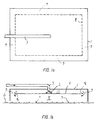
- Figs 1a and 1b show a cover 1 with an inlet 2 for supply of steam and a pipe 3 connected with the inlet 2.
- a baffle or guide plate 4 is provided which establishes a horizontal, radial duct 11, thus providing for distribution of steam from the inlet 2 to be discharged diffusely in the space 5 between the cover 1 or the guide plate 4 and the ground 6, on which weed 7 to be destroyed is present.
- the steam is thereby guided from the inlet 2 over the baffle plate 4 to its edge 8, at which a slit 9 opening down into the space 5 is provided.
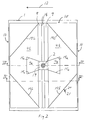
- Figs 2-4 show an apparatus according to the present invention with an upwards open and downwards closed cover 1, under which a steam discharge device 10 is provided.
- the apparatus has, during operation, an intended travelling direction 21 and thus a front end 13 and a back end 14.
- the steam discharge device is in the embodiment shown symmetrical about a vertical plane transversely to the travelling direction 12 and comprises an inlet 2, through which steam may be led into two first horizontal duct sections 11a defined by a first horizontal guide plate 4a and diverging side walls 15a and which extends in each their direction forwards and backwards, respectively.
- An inlet guide member 19 distributes the steam between the two first duct sections 11a.
- the two first duct sections 11a end in each their respective second duct section 11b defined by second horizontal guide plates 4b and second diverging side walls 15b.
- the second duct sections 11b extend in opposite directions relative to their respective connected first duct sections 11a.
- the second duct sections 11b lead to each their respective slit-shaped outlet 9, through which steam is let out into the space 5 above the ground 6.
- the two outlets 9 are separated by an outlet guide member 18 which guides the steam down into the space 5.
- the outlet guide member 18 is in Fig. 2 shown at the points where it intersects the plane of the guide plates 4b.
- the cover may for instance have a length of approx. 100 cm, a width of 140 cm and a height of 20 cm, and the steam discharge device may for instance be approx. 100 cm long, 120 cm wide and 10 cm high, the space 5 also being approx. 10 cm high.
- the outlets 9 may each have a width of 10-40 mm, preferably 15-35 mm and further preferably 20-30 mm. These dimensions are suitable in connection with a steam generator of 160 kW and a travelling speed of approx. 3.6 km/h corresponding to a treatment time of 1 sec.
- the steam cloud will in the space 5 acquire a concentration or temperature profile which will depend on i.a. the supply speed and the amount of weed under the cover 1, as the steam will condensate on this weed. It is therefore possible to measure the temperature at a certain point in the space 5 and by means of a control device (not shown) to control the steam supply on basis of the temperature measurement.
- a control device not shown
- FIGs 2 and 4 an arm 20 with a temperature sensor 21 at the end is shown.
- a lower temperature will indicate an increased amount of weed 7 in the space 5 and consequently an increased need for steam for scorching this weed 7.
- the surface on which the steam can condensate will be smaller, i.e. the need for steam is reduced and the temperature will increase. This increase may be used for reducing the steam supply speed by means of the control device.
- the said control device may be of a completely conventional type, preferably with electronic temperature measurement for the sake of convenience, but any suitable type may be used.
- outlets 9 are in the example shown placed centrally under the cover 1, seen i the travelling direction 12. This central positioning is not imperative, but it is according to the invention of importance that the outlets 9 are positioned at a distance from the front end 13 and the back end 14, respectively, in consideration of the formation of a steam cloud with a profile as mentioned.
- at least one outlet 9 is provided, said outlet being positioned more than 20% of the length of the cover 1 from the front end 13 and the back end 14.
- steam discharge devices 10 may be placed under a longer cover 1 in extension of each other, seen in the travelling direction 12, in order to attain a longer scorching time of the weed at a given travelling speed of the weed destroying apparatus.
- the outlet or outlets are preferably designed such that they do not surround any areas under the cover, as such surrounded areas are likely to confine comparatively cold air which may isolate part of the weed from the steam and thus prevent an effective treatment.
Landscapes
- Life Sciences & Earth Sciences (AREA)
- Engineering & Computer Science (AREA)
- Insects & Arthropods (AREA)
- Pest Control & Pesticides (AREA)
- Wood Science & Technology (AREA)
- Zoology (AREA)
- Environmental Sciences (AREA)
- Soil Working Implements (AREA)
- Catching Or Destruction (AREA)
Priority Applications (1)
| Application Number | Priority Date | Filing Date | Title |
|---|---|---|---|
| EP99610020A EP1038440A1 (de) | 1999-03-19 | 1999-03-19 | Vorrichtung zur Beseitigung unerwünschten Pflanzenwuchses mittels Dampf |
Applications Claiming Priority (1)
| Application Number | Priority Date | Filing Date | Title |
|---|---|---|---|
| EP99610020A EP1038440A1 (de) | 1999-03-19 | 1999-03-19 | Vorrichtung zur Beseitigung unerwünschten Pflanzenwuchses mittels Dampf |
Publications (1)
| Publication Number | Publication Date |
|---|---|
| EP1038440A1 true EP1038440A1 (de) | 2000-09-27 |
Family
ID=8242550
Family Applications (1)
| Application Number | Title | Priority Date | Filing Date |
|---|---|---|---|
| EP99610020A Withdrawn EP1038440A1 (de) | 1999-03-19 | 1999-03-19 | Vorrichtung zur Beseitigung unerwünschten Pflanzenwuchses mittels Dampf |
Country Status (1)
| Country | Link |
|---|---|
| EP (1) | EP1038440A1 (de) |
Cited By (11)
| Publication number | Priority date | Publication date | Assignee | Title |
|---|---|---|---|---|
| KR100731681B1 (ko) | 2006-06-08 | 2007-06-25 | 허만국 | 스팀을 이용한 잡초제거방법 및 장치 |
| LT5532B (lt) | 2007-01-11 | 2008-12-29 | Lietuvos Žemės Ūkio Universitetas | Mobilus piktžolių terminio naikinimo įrenginys |
| WO2009013154A1 (en) * | 2007-07-20 | 2009-01-29 | Force Technology | Method and device for killing weeds |
| FR2934463A1 (fr) * | 2008-08-01 | 2010-02-05 | Jacques Corbier | Dispositif traitement continu antiparasites, antibacterien, maladie et desherbant par confinement des plants en enceinte chauffee, saturee de vapeur, embarquee sur porte-outils, ou a poste fixe |
| JP2017006060A (ja) * | 2015-06-23 | 2017-01-12 | 東急建設株式会社 | 蒸気除草方法および蒸気除草装置 |
| EP3539378A1 (de) * | 2018-03-15 | 2019-09-18 | Exel Industries | Thermische unkrautvernichter |
| FR3078861A1 (fr) * | 2018-03-15 | 2019-09-20 | Exel Industries | Diffuseur pour desherbeur |
| FR3078860A1 (fr) * | 2018-03-15 | 2019-09-20 | Exel Industries | Diffuseur pour desherbeur |
| CN110268856A (zh) * | 2018-03-15 | 2019-09-24 | 艾格赛尔工业公司 | 热力除草机 |
| JP2022077436A (ja) * | 2020-11-11 | 2022-05-23 | カワサキ機工株式会社 | 圃園用除草装置並びにこれを用いた圃園管理方法 |
| DK202330057A1 (da) * | 2023-06-01 | 2025-01-07 | Weed Fighter Aps | Dampdyse til behandling af uønsket plantevækst og alger |
Citations (3)
| Publication number | Priority date | Publication date | Assignee | Title |
|---|---|---|---|---|
| WO1994026102A1 (en) * | 1993-05-07 | 1994-11-24 | Waipuna International Limited | Vegetation control method and apparatus |
| US5385106A (en) * | 1992-08-24 | 1995-01-31 | Langshaw; Eric | Hot water/steam weed killing system |
| NL1009183C2 (nl) | 1997-05-16 | 1998-11-17 | Wr Damp Aps | Inrichting voor het vernietigen van ongewenste vegetatie. |
-
1999
- 1999-03-19 EP EP99610020A patent/EP1038440A1/de not_active Withdrawn
Patent Citations (3)
| Publication number | Priority date | Publication date | Assignee | Title |
|---|---|---|---|---|
| US5385106A (en) * | 1992-08-24 | 1995-01-31 | Langshaw; Eric | Hot water/steam weed killing system |
| WO1994026102A1 (en) * | 1993-05-07 | 1994-11-24 | Waipuna International Limited | Vegetation control method and apparatus |
| NL1009183C2 (nl) | 1997-05-16 | 1998-11-17 | Wr Damp Aps | Inrichting voor het vernietigen van ongewenste vegetatie. |
Non-Patent Citations (1)
| Title |
|---|
| DATABASE WPI Section PQ Week 9908, Derwent World Patents Index; Class P14, AN 99-094267 * |
Cited By (13)
| Publication number | Priority date | Publication date | Assignee | Title |
|---|---|---|---|---|
| KR100731681B1 (ko) | 2006-06-08 | 2007-06-25 | 허만국 | 스팀을 이용한 잡초제거방법 및 장치 |
| LT5532B (lt) | 2007-01-11 | 2008-12-29 | Lietuvos Žemės Ūkio Universitetas | Mobilus piktžolių terminio naikinimo įrenginys |
| WO2009013154A1 (en) * | 2007-07-20 | 2009-01-29 | Force Technology | Method and device for killing weeds |
| FR2934463A1 (fr) * | 2008-08-01 | 2010-02-05 | Jacques Corbier | Dispositif traitement continu antiparasites, antibacterien, maladie et desherbant par confinement des plants en enceinte chauffee, saturee de vapeur, embarquee sur porte-outils, ou a poste fixe |
| JP2017006060A (ja) * | 2015-06-23 | 2017-01-12 | 東急建設株式会社 | 蒸気除草方法および蒸気除草装置 |
| FR3078861A1 (fr) * | 2018-03-15 | 2019-09-20 | Exel Industries | Diffuseur pour desherbeur |
| EP3539378A1 (de) * | 2018-03-15 | 2019-09-18 | Exel Industries | Thermische unkrautvernichter |
| FR3078860A1 (fr) * | 2018-03-15 | 2019-09-20 | Exel Industries | Diffuseur pour desherbeur |
| CN110268856A (zh) * | 2018-03-15 | 2019-09-24 | 艾格赛尔工业公司 | 热力除草机 |
| GB2572026B (en) * | 2018-03-15 | 2022-08-31 | Exel Ind Sa | Thermal Weeders |
| EP4331357A3 (de) * | 2018-03-15 | 2024-05-22 | Exel Industries | Thermischer unkrautdiffusor |
| JP2022077436A (ja) * | 2020-11-11 | 2022-05-23 | カワサキ機工株式会社 | 圃園用除草装置並びにこれを用いた圃園管理方法 |
| DK202330057A1 (da) * | 2023-06-01 | 2025-01-07 | Weed Fighter Aps | Dampdyse til behandling af uønsket plantevækst og alger |
Similar Documents
| Publication | Publication Date | Title |
|---|---|---|
| EP1038440A1 (de) | Vorrichtung zur Beseitigung unerwünschten Pflanzenwuchses mittels Dampf | |
| US4987957A (en) | Deflector for side wall sprinkler head | |
| US4296815A (en) | Deflector with converging lower tines for horizontal sprinkler | |
| JP3020290B2 (ja) | 流体の流れを遮断する為の方法と装置 | |
| DE3815212A1 (de) | Papierbahnbehandlungsvorrichtung | |
| CA2482603A1 (en) | Sprinkler head with improved flow | |
| JPS5938360B2 (ja) | 抄紙機の原料調整装置 | |
| RU2008137282A (ru) | Распределительное устройство для применения при разливке металла | |
| DE4332050A1 (de) | Lüftungsvorrichtung und Lüftungsverfahren | |
| JP3318674B2 (ja) | 土壌の加熱消毒装置 | |
| US3831859A (en) | Discharge means for agricultural foam | |
| JP2007295869A (ja) | 走行型茶園防除機における薬液散布装置 | |
| DE3343731C2 (de) | Als Düsenkranz ausgebildete Vorrichtung zur Verteilung von Luft | |
| DE2328186A1 (de) | Einrichtung zum kuehlen und/oder erwaermen von raeumen | |
| DE10124396A1 (de) | Kondensationsbrühtunnel für Schlachttiere | |
| GB1601896A (en) | Machine for pneumatically spreading granular material | |
| JPH0519058B2 (de) | ||
| NL8100287A (nl) | Luchtconditioneerinrichting, luchtbevochtiger en werkwijze voor het conditioneren van lucht. | |
| US5048314A (en) | Apparatus for applying a treatment fluid having a flow homogenizing baffle | |
| DE102008031219B3 (de) | Hybridkühlturm | |
| CH654901A5 (en) | Device for conditioning the air inside a room | |
| EP0873178B1 (de) | Zerstäuber | |
| EP1422481B1 (de) | Deckenkonvektor | |
| DE19753416C2 (de) | Dampfkasten für Karton- oder Papiermaschine | |
| DE10001073A1 (de) | Verfahren und Vorrichtung zum Verhindern einer unerwünschten Abkühlung der Bandkantenbereiche eines Gußstranges |
Legal Events
| Date | Code | Title | Description |
|---|---|---|---|
| PUAI | Public reference made under article 153(3) epc to a published international application that has entered the european phase |
Free format text: ORIGINAL CODE: 0009012 |
|
| 17P | Request for examination filed |
Effective date: 19991008 |
|
| AK | Designated contracting states |
Kind code of ref document: A1 Designated state(s): AT BE CH CY DE DK ES FI FR GB GR IE IT LI LU MC NL PT SE |
|
| AX | Request for extension of the european patent |
Free format text: AL;LT;LV;MK;RO;SI |
|
| RAP1 | Party data changed (applicant data changed or rights of an application transferred) |
Owner name: SCANECO APS |
|
| AKX | Designation fees paid |
Free format text: AT BE CH CY DE DK ES FI FR GB GR IE IT LI LU MC NL PT SE |
|
| AXX | Extension fees paid |
Free format text: AL PAYMENT 20010323;LT PAYMENT 20010323;LV PAYMENT 20010323;MK PAYMENT 20010323;RO PAYMENT 20010323;SI PAYMENT 20010323 |
|
| GRAG | Despatch of communication of intention to grant |
Free format text: ORIGINAL CODE: EPIDOS AGRA |
|
| 17Q | First examination report despatched |
Effective date: 20020524 |
|
| GRAG | Despatch of communication of intention to grant |
Free format text: ORIGINAL CODE: EPIDOS AGRA |
|
| GRAH | Despatch of communication of intention to grant a patent |
Free format text: ORIGINAL CODE: EPIDOS IGRA |
|
| STAA | Information on the status of an ep patent application or granted ep patent |
Free format text: STATUS: THE APPLICATION IS DEEMED TO BE WITHDRAWN |
|
| 18D | Application deemed to be withdrawn |
Effective date: 20030403 |