EP1038513A2 - Treppensteigvorrichtung - Google Patents
Treppensteigvorrichtung Download PDFInfo
- Publication number
- EP1038513A2 EP1038513A2 EP00101128A EP00101128A EP1038513A2 EP 1038513 A2 EP1038513 A2 EP 1038513A2 EP 00101128 A EP00101128 A EP 00101128A EP 00101128 A EP00101128 A EP 00101128A EP 1038513 A2 EP1038513 A2 EP 1038513A2
- Authority
- EP
- European Patent Office
- Prior art keywords
- climbing
- sensor
- drive speed
- drive
- control device
- Prior art date
- Legal status (The legal status is an assumption and is not a legal conclusion. Google has not performed a legal analysis and makes no representation as to the accuracy of the status listed.)
- Granted
Links
Images






Classifications
-
- A—HUMAN NECESSITIES
- A61—MEDICAL OR VETERINARY SCIENCE; HYGIENE
- A61G—TRANSPORT, PERSONAL CONVEYANCES, OR ACCOMMODATION SPECIALLY ADAPTED FOR PATIENTS OR DISABLED PERSONS; OPERATING TABLES OR CHAIRS; CHAIRS FOR DENTISTRY; FUNERAL DEVICES
- A61G5/00—Chairs or personal conveyances specially adapted for patients or disabled persons, e.g. wheelchairs
- A61G5/06—Chairs or personal conveyances specially adapted for patients or disabled persons, e.g. wheelchairs with obstacle mounting facilities, e.g. for climbing stairs, kerbs or steps
- A61G5/061—Chairs or personal conveyances specially adapted for patients or disabled persons, e.g. wheelchairs with obstacle mounting facilities, e.g. for climbing stairs, kerbs or steps for climbing stairs
-
- A—HUMAN NECESSITIES
- A61—MEDICAL OR VETERINARY SCIENCE; HYGIENE
- A61G—TRANSPORT, PERSONAL CONVEYANCES, OR ACCOMMODATION SPECIALLY ADAPTED FOR PATIENTS OR DISABLED PERSONS; OPERATING TABLES OR CHAIRS; CHAIRS FOR DENTISTRY; FUNERAL DEVICES
- A61G5/00—Chairs or personal conveyances specially adapted for patients or disabled persons, e.g. wheelchairs
- A61G5/06—Chairs or personal conveyances specially adapted for patients or disabled persons, e.g. wheelchairs with obstacle mounting facilities, e.g. for climbing stairs, kerbs or steps
- A61G5/063—Chairs or personal conveyances specially adapted for patients or disabled persons, e.g. wheelchairs with obstacle mounting facilities, e.g. for climbing stairs, kerbs or steps with eccentrically mounted wheels
-
- B—PERFORMING OPERATIONS; TRANSPORTING
- B62—LAND VEHICLES FOR TRAVELLING OTHERWISE THAN ON RAILS
- B62B—HAND-PROPELLED VEHICLES, e.g. HAND CARTS OR PERAMBULATORS; SLEDGES
- B62B5/00—Accessories or details specially adapted for hand carts
- B62B5/02—Accessories or details specially adapted for hand carts providing for travelling up or down a flight of stairs
- B62B5/026—Accessories or details specially adapted for hand carts providing for travelling up or down a flight of stairs with spiders or adapted wheels
Definitions
- the invention relates to a stair climbing device, for example for wheelchairs for the disabled, with a Carrier unit and one connected to the carrier unit Climbing unit, the climbing unit being at least one Has climbing element by a drive motor drivable and is designed so that it with each nearest landing of a stair in contact arrive and the stair climbing device on the can raise or lower the nearest landing.
- Such a stair climbing device is, for example, out of known from DE 37 13 564 C2.
- Stair climbing device for wheelchairs encompasses the invention any other stair climbing devices with or without external operators to transport loads or People on stairs are suitable.
- Stairs are especially for wheelchair users and Disabled people are an ever-present problem.
- a Stair climbing device of the type mentioned allows for example, that assistants have a wheelchair user or handicapped people without significant physical exertion a staircase using this stair climbing device alone can carry up or down.
- the assistant now tilts the Stair climbing device with attached wheelchair to yourself into balance. When the ideal tilt position is reached the assistant only feels a minimal pressure front or back.
- a climbing element now comes with the stair climbing device touches the nearest landing and lifts the Stair climbing device to the nearest landing up. This process is repeated until the Stair climbing device on the top step of the stairs has arrived. Descending a staircase is done analogously in the same way.
- the invention is based on the technical problem generic stair climbing device to that effect improve that the operation is facilitated.
- the climbing unit Can be operated with different drive speeds is, the drive speed shortly before touchdown of a climbing element on the nearest landing compared to a first predetermined drive speed is reducible so that a soft touchdown is achieved and after landing on the nearest landing back to the first predetermined drive speed is increased.
- the Stair climbing device an electronic control device to control the drive speed of the climbing unit on.
- at least one sensor can be provided which is assigned to a climbing element, the sensor for this purpose is designed to a certain position of the climbing element detect and send a signal to the control device, and the control device is designed to control the Drive speed of the climbing element depending on to control the signal from the sensor.
- first HAL sensor provided to detect a specific location of the Climbing element is used.
- a second HAL sensor can be used for counting of the revolutions of the drive motor.
- the Control device can from the signals of the first HAL sensor and the second HAL sensor the current position of the Determine the climbing element and in a first predetermined Position of the climbing element to lower the drive speed and in a second predetermined position of the climbing element Increase drive speed.
- the first predetermined location and the second predetermined position are based here preferably at a typical step height of a staircase. It can be permanently programmed values that for example in a memory or a program of electronic control device are stored. There is also the possibility of the first predetermined position and the second freely program the predetermined position. This can be a Device users this the special local Adjust conditions optimally.
- a Distance sensor can be provided, which is designed to the distance of the climbing element from a step surface detect and depending on this distance a signal to deliver to the control device, the Control device the drive speed of the Rising element depending on the signal of the Distance sensor controls.
- the distance sensor it can an infrared sensor, an ultrasonic sensor or a mechanical sensor in which, for example, a spring-loaded element over a certain path is movable and this path is grasped, act.
- the distance sensor it can an infrared sensor, an ultrasonic sensor or a mechanical sensor in which, for example, a spring-loaded element over a certain path is movable and this path is grasped, act.
- the electronic control unit controls the drive motor as Response to a corresponding signal from the distance sensor such that the drive speed is reduced.
- a subsequent increase in drive speed can for example, at a certain time interval lowering the drive speed or in response on the signal of another distance sensor.
- the Lowering the drive speed and raising the Drive speed according to a ramp function certain length and certain steepness.
- the Lowering can be continuous or certain Stages, linear, progressive or degressive and over different periods of time occur.
- different ramps can be provided.
- the single ones Ramp function parameters can also be used for lowering the drive speed and for lifting the Drive speed freely independent of each other be programmable. This allows a user of the Device this for special purposes and others Adjust boundary conditions optimally.
- the climbing unit has two stair climbing devices Impeller pairs on, with each impeller the function of a Has climbing element. Both wheels of a pair of wheels are opposite the carrier unit by one parallel to it Center axis shaft pivotally mounted.
- the climbing unit can be one or have several chain drives provided with cams an upward or downward movement of the stair climbing device the edge of the stairs. For this, the Stair climbing device brought up to the edge of the stairs until a cam of the chain drive engages the step edge, and the Stair climbing device to the next higher or the level below raises or lowers.
- the climbing unit can be a stair climbing device have several stilts that describe a curved path, being driven by a crank mechanism or eccentric become.
- This cam track is, depending on the embodiment suitable for the vertical and lateral distance of one step overcome.
- the stilt sets accordingly given direction of climb in each case on the next higher or level below and lifts the Stair climbing device to this step or lowers it them off.
- Fig. 1 shows a schematic side view of a wheelchair 10 for the disabled, with a seat frame 11, with a Chair frame 12 is connected, the front in two footbridges 13 ends, on each of which a steering roller 14 rotatably mounted is. 1 is only the left one Swivel castor 14 can be seen.
- On the chair frame 12 is a Support frame for a stair climbing device 15 attached, the one shown in Fig. 1 left support plate 16 and the invisible right side of the wheelchair 10 one has the same right support plate 16.
- On each support plate 16 a pair of impellers 17a and 17b are arranged, one of which in the normal position shown in FIGS. 1 and 4 or Rest position of the stair climbing device 15 one on the Lane 18 is running.
- Fig. 1 are the center points 19a and 19b of the two wheels 17a and 17b as well eccentrically arranged and in the support plate 16 mounted drive shafts 20a and 20b with associated Drive sprockets 21a and 21b shown. Also are the enveloping circles 22a and 22b, which the Extent of the impellers 17a and 17b as they move about describes eccentric drive shafts 20a and 20b.
- the mutual distance between the two drive shafts 20a and 20b is 2a, i.e. twice the value of the distance a Center 19a or 19b of the impeller 17a or 17b from the Axis of its eccentric drive shaft 20a or 20b.
- Fig. 1 shows a under the seat frame 11 Box 23 for housing batteries from which the common, with one also not shown electronic control device coupled electrical Drive motor is operated. He moves one from FIG. 2 apparent endless chain 24 that goes over the two Sprockets 21a and 21b of the two drive shafts 20a and 20b to achieve a respective sense and the same rapid rotary movement of the two drive shafts 20a, 20b is led. Between the two sprockets 21a and 21b the common drive chain 24 via a sliding body 25 performed, which can also be replaced by a deflection sprocket could. It is understood that on the right side of the Wheelchairs 10 a same pair of wheels in exactly the same way and arranged and driven.
- FIG. 3 The sectional view of Fig. 3 shows that the support plate 16 from two spaced parallel ones Plate walls 16.1 and 16.2 exist between which the common drive chain 24, only by one dash-dotted line is indicated, is guided and the Sprockets 21a and 21b are arranged on the as Hollow shafts formed in the support plate 16.1 / 16.2 mounted drive shafts 20a and 20b are attached.
- FIG. 3 From the sectional view of Fig. 3 are also the structure the impellers and one acting on the impellers Brake device visible.
- Each of the two the same trained impellers 17a and 17b of a pair of impellers a hub disc 26a, 26b, which with the eccentric Drive shaft 20a, 20b is firmly connected and one has central axis bolts 27a, 27b.
- On the axle bolt 27a, 27b a bearing sleeve 28a, 28b is slid onto it a roller bearing directional lock 29a, 29b is attached which in turn ends in a rubber tire 31a, 31b Running ring 30a, 30b is mounted.
- the bearing sleeve 28a, 28b is provided with a sprocket 32a, 32b, which also has a Fig. 2 apparent endless chain 33a, 33b with a coaxial to the associated hollow drive shaft 20a, 20b on one Shaft journal mounted concentrically in the drive shaft 34a, 34b coupled chain wheel 35a, 35b is coupled.
- the Shaft journal 34a, 34b is in a manner not shown with the brake disc of an electromagnetically operated Brake device 36a, 36b connected.
- the two sprockets 32a, 32b and 35a, 35b are the same size, so that a chain drive with the gear ratio 1: 1 results.
- the electromagnetic braking device 36a, 36b via a control device, not shown activated the shaft journal 34a, 34b is blocked, which means that the bearing sleeve 28a, 28b is blocked, too that the roller bearing directional lock 29a, 29b a rotation of the Wheel rim 30a, 30b of the respective wheel 17a, 17b only in allowed in one direction. In the other direction it is relevant impeller 17a, 17b blocked.
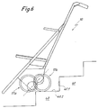
- FIG. 4 shows the Wheelchair 10 in a normal driving position, in which the about two wheels 17a and 17b of both pairs of wheels are arranged one above the other and the impeller 17a on the Tread 18 rests. In this position the Wheelchair 10 with the chain 24 stationary and without the chain inserted Move the brakes freely. In this normal running position the wheelchair 10 backwards against the front edge 40.1 first step 40 moved up, the brakes applied and then the drive motor for the chain 24 the Stair climbing device 15 turned on.
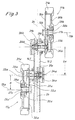
- Fig. 9 shows a single longitudinal section through an impeller 17b 'of a stair climbing device in which the electromagnetic brake device on the hub disc 30b ' is arranged. This results in a larger braking area.
- An armature disk 42 is connected to the running ring 30b ' biased by springs in the braking position, in which you fastened locking bolt 43 in a on the rim 30b ' attached hole ring 46 engage so that in the event of a power failure the braking device takes effect automatically.
- the brake is fixed on one with the bearing sleeve 28b ' connected counter disc 45 arranged magnetic action 44th excited and thereby released the brake.
- a directional locking bearing 29b ' is here on the shaft journal 34b' arranged.
- a Knee lever brake can be provided, in which a below the Center axis of the impeller pivotally mounted lever a spring element is pressed against the driving surface.
- a feeler roller is rotatable arranged that when you push the Stair climbing device for the purpose of lowering onto the seen the next lower landing in the direction of movement is arranged in front of the central axis of the impeller.
- the lever has a brake shoe attached to the side, with the impeller can engage, preferably engages in a radial undercut of the impeller.
- the first embodiment realizes a so-called programmatically controlled reduction of Drive speed of the electric drive motor.
- the electronic control device recognizes the situation of the riser in the above Embodiment thus the position of the impeller 17a or 17b.
- a HAL sensor is attached at a suitable location used.
- a second, also on a suitable one The HAL sensor installed counts the revolutions of the electric drive motor. From the signals from these two The electronic control device detects HAL sensors a switchable electronic control program, when that Slow down the impeller. This time is on one typical step height matched. Then increasing the Drive speed is also due to the Control program function, for example after a certain one Number of revolutions of the electric drive motor.
- a so-called sensor-controlled reduction of the drive speed of the electric drive motor are on the Stair climbing device one or more distance sensors appropriate. These can be infrared sensors, Act ultrasonic sensors or mechanical sensors, the spring-loaded slidable over a certain distance are, this distance is detected, or an elastic deformable element, the deformation of which, for example, via Strain gauge, is detected.
- the distance sensor detects the distance of the moving Rising element, in the above Embodiment thus the position of the impeller 17a and 17b, respectively next step surface.
- the electronic control device initiates a threshold value in response to a corresponding signal from the Distance sensor the speed reduction.
- Distance sensors can be used on the climbing elements, for example on the wheels, as well as on one stationary part of the stair climbing device.
- stair climbing devices can be provided be with an existing commercial wheelchair can be connected.
- the principle according to the invention is also applicable to any other Stair climbing devices applicable with or without external operators to transport loads or People on stairs are suitable.
Landscapes
- Engineering & Computer Science (AREA)
- Life Sciences & Earth Sciences (AREA)
- Animal Behavior & Ethology (AREA)
- General Health & Medical Sciences (AREA)
- Public Health (AREA)
- Veterinary Medicine (AREA)
- Health & Medical Sciences (AREA)
- Combustion & Propulsion (AREA)
- Chemical & Material Sciences (AREA)
- Transportation (AREA)
- Mechanical Engineering (AREA)
- Handcart (AREA)
- Buildings Adapted To Withstand Abnormal External Influences (AREA)
- Soil Working Implements (AREA)
- Steps, Ramps, And Handrails (AREA)
- Types And Forms Of Lifts (AREA)
- Sorption Type Refrigeration Machines (AREA)
- Semiconductor Lasers (AREA)
Abstract
Description
Claims (16)
- Treppensteigvorrichtung, beispielsweise für Rollstühle für Gehunfähige, mit einer Trägereinheit (11, 12) und einer mit der Trägereinheit (11, 12) verbundenen Steigeinheit, wobei die Steigeinheit mindestens ein Steigelement (17a, 17b) aufweist, das durch einen Antriebsmotor antreibbar und so ausgebildet ist, daß es mit dem jeweils nächstgelegenen Treppenabsatz einer Treppe in Berührung gelangen und die Treppensteigvorrichtung auf den nächstgelegenen Treppenabsatz heraufheben oder absenken kann,
dadurch gekennzeichnet,
daß die Steigeinheit mit unterschiedlichen Antriebsgeschwindigkeiten betreibbar ist, wobei die Antriebsgeschwindigkeit kurz vor dem Aufsetzen eines Steigelements (17a, 17b) auf den nächstgelegenen Treppenabsatz gegenüber einer ersten vorbestimmten Antriebsgeschwindigkeit reduzierbar ist, so daß ein weiches Aufsetzen erreicht wird, und nach dem Aufsetzen auf den nächstgelegenen Treppenabsatz wieder auf die erste vorbestimmte Antriebsgeschwindigkeit erhöht wird. - Vorrichtung nach Anspruch 1, gekennzeichnet durch eine elektronische Steuereinrichtung zur Steuerung der Antriebsgeschwindigkeit der Steigeinheit.
- Vorrichtung nach Anspruch 2, gekennzeichnet durch mindestens einen Sensor, der einem Steigelement (17a, 17b) zugeordnet ist, wobei der Sensor dazu ausgelegt ist, eine bestimmte Lage des Steigelements (17a, 17b) zu erfassen und ein Signal an die Steuereinrichtung abzugeben, und die Steuereinrichtung dazu ausgelegt ist, die Antriebsgeschwindigkeit des Steigelements (17a, 17b) in Abhängigkeit von dem Signal des Sensors zu steuern.
- Vorrichtung nach Anspruch 3, gekennzeichnet durch einen ersten HAL-Sensor zum Erfassen einer bestimmten Lage des Steigelements (17a, 17b).
- Vorrichtung nach Anspruch 4, gekennzeichnet durch einen zweiten HAL-Sensor zum Zählen der Umdrehungen des Antriebsmotors.
- Vorrichtung nach Anspruch 5, dadurch gekennzeichnet, daß die Steuereinrichtung dazu ausgelegt ist, aus den Signalen des ersten HAL-Sensors und des zweiten HAL-Sensors die momentane Lage des Steigelements (17a, 17b) zu ermitteln, in einer ersten vorbestimmten Lage des Steigelements (17a, 17b) die Antriebsgeschwindigkeit abzusenken und in einer zweiten vorbestimmten Lage des Steigelements (17a, 17b) die Antriebsgeschwindigkeit zu erhöhen.
- Vorrichtung nach Anspruch 6, dadurch gekennzeichnet, daß die erste vorbestimmte Lage und die zweite vorbestimmte Lage basierend auf einer typischen Stufenhöhe einer Treppe festgelegt sind.
- Vorrichtung nach Anspruch 6, dadurch gekennzeichnet, daß die erste vorbestimmte Lage und die zweite vorbestimmte Lage frei programmierbar sind.
- Vorrichtung nach Anspruch 3, gekennzeichnet durch einen Entfernungssensor, der dazu ausgelegt ist, den Abstand des Steigelements (17a, 17b) von einer Stufenoberfläche zu detektieren und in Abhängigkeit von diesem Abstand ein Signal an die Steuereinrichtung abzugeben, wobei die Steuereinrichtung die Antriebsgeschwindigkeit des Steigelements (17a, 17b) in Abhängigkeit von dem Signal des Entfernungssensors steuert.
- Vorrichtung nach Anspruch 9, dadurch gekennzeichnet, daß der Entfernungssensor ein Infrarotsensor, ein Ultraschallsensor, oder eine mechanische Sensoreinrichtung ist.
- Vorrichtung nach Anspruch 9 oder 10, dadurch gekennzeichnet, daß die Antriebsgeschwindigkeit abgesenkt wird, wenn ein vorbestimmter Abstand unterschritten wird.
- Vorrichtung nach Anspruch 11, dadurch gekennzeichnet, daß die Antriebsgeschwindigkeit erhöht wird, wenn die Steigeinheit über eine vorbestimmte Zeitspanne mit abgesenkter Antriebsgeschwindigkeit betrieben wurde.
- Vorrichtung nach einem der Ansprüche 2 bis 12, dadurch gekennzeichnet, daß die elektronische Steuereinrichtung abschaltbar ist.
- Vorrichtung nach einem der Ansprüche 2 bis 13, dadurch gekennzeichnet, daß die Absenkung der Antriebsgeschwindigkeit und das Anheben der Antriebsgeschwindigkeit jeweils nach einer Rampenfunktion bestimmter Länge und bestimmter Steilheit erfolgen.
- Vorrichtung nach Anspruch 14, dadurch gekennzeichnet, daß die einzelnen Parameter der Rampenfunktionen für die Absenkung der Antriebsgeschwindigkeit und das Anheben der Antriebsgeschwindigkeit unabhängig voneinander frei programmierbar sind.
- Vorrichtung nach einem der vorstehenden Ansprüche, dadurch gekennzeichnet, daß die Steigeinheit zwei als Steigelemente (17a, 17b) fungierende Laufradpaare, deren beide Laufräder gegenüber der Trägereinheit (11, 12) um eine parallel zu ihrer Mittelachse verlaufende Welle verschwenkbar gelagert sind, aufweist.
Applications Claiming Priority (2)
| Application Number | Priority Date | Filing Date | Title |
|---|---|---|---|
| DE19912932A DE19912932C1 (de) | 1999-03-22 | 1999-03-22 | Treppensteigvorrichtung |
| DE19912932 | 1999-03-22 |
Publications (3)
| Publication Number | Publication Date |
|---|---|
| EP1038513A2 true EP1038513A2 (de) | 2000-09-27 |
| EP1038513A3 EP1038513A3 (de) | 2001-09-12 |
| EP1038513B1 EP1038513B1 (de) | 2005-07-27 |
Family
ID=7901985
Family Applications (1)
| Application Number | Title | Priority Date | Filing Date |
|---|---|---|---|
| EP00101128A Expired - Lifetime EP1038513B1 (de) | 1999-03-22 | 2000-01-21 | Treppensteigvorrichtung |
Country Status (4)
| Country | Link |
|---|---|
| EP (1) | EP1038513B1 (de) |
| AT (1) | ATE300271T1 (de) |
| DE (2) | DE19912932C1 (de) |
| DK (1) | DK1038513T3 (de) |
Cited By (4)
| Publication number | Priority date | Publication date | Assignee | Title |
|---|---|---|---|---|
| CN1989919B (zh) * | 2005-12-30 | 2012-03-07 | 财团法人工业技术研究院 | 电动轮椅 |
| EP2644473A3 (de) * | 2012-03-30 | 2017-06-21 | AAT Alber Antriebstechnik GmbH | Treppensteigvorrichtung und Steuerungsverfahren deren Steigeinheit |
| CN107728611A (zh) * | 2017-08-23 | 2018-02-23 | 北京石油化工学院 | 一种多功能爬楼座椅控制系统 |
| CN109927806A (zh) * | 2019-03-14 | 2019-06-25 | 中南大学 | 一种便携式爬楼机 |
Families Citing this family (14)
| Publication number | Priority date | Publication date | Assignee | Title |
|---|---|---|---|---|
| EP1186284A1 (de) * | 2000-09-08 | 2002-03-13 | Gisbert Weiss Gmbh | Rollstuhl mit Treppensteigvorrichtung |
| EP1319382B1 (de) | 2001-12-13 | 2006-07-26 | Ulrich Alber GmbH | Treppensteigvorrichtung |
| DE10161220B4 (de) * | 2001-12-13 | 2005-06-16 | Ulrich Alber Gmbh | Treppensteigvorrichtung |
| DE10248889B4 (de) * | 2001-12-13 | 2005-10-13 | Ulrich Alber Gmbh | Treppensteigvorrichtung |
| US7770904B2 (en) | 2005-04-14 | 2010-08-10 | Nmhg Oregon, Llc | Stability system for an industrial vehicle |
| US20090309319A1 (en) * | 2006-03-06 | 2009-12-17 | Sterraclimb Llc | Stairclimbing and Descending Hand Truck |
| DE102007014159A1 (de) * | 2007-01-13 | 2008-07-17 | Waltraud Jettinger | Handgeführtes Transportgerät, insbesondere Einkaufsroller |
| JP2010534156A (ja) * | 2007-02-12 | 2010-11-04 | ステラクライム リミテッド ライアビリティ カンパニー | 階段昇降車両 |
| US7669862B2 (en) | 2007-04-27 | 2010-03-02 | Sterraclimb Llc | Foldable spider wheel for ascending and descending stairs |
| DE102008044516B3 (de) | 2008-09-11 | 2009-10-29 | Ulrich Alber Gmbh | Treppensteigvorrichtung |
| DE102010037729B4 (de) | 2010-04-27 | 2021-10-14 | Alber Gmbh | Treppensteigvorrichtung |
| DE102018210448A1 (de) * | 2018-06-27 | 2020-01-02 | Robert Bosch Gmbh | Transportvorrichtung, insbesondere Kinderwagen, mit einer elektrischen Antriebseinheit |
| DE102021202262A1 (de) | 2021-03-09 | 2022-09-15 | Robert Bosch Gesellschaft mit beschränkter Haftung | Transportvorrichtung und Verfahren für eine Transportvorrichtung |
| CN113081527A (zh) * | 2021-04-21 | 2021-07-09 | 玉林师范学院 | 一种智能化多功能轮椅 |
Citations (1)
| Publication number | Priority date | Publication date | Assignee | Title |
|---|---|---|---|---|
| DE3713564A1 (de) | 1987-04-23 | 1988-11-10 | Haas & Alber Haustechnik Und A | Treppensteigvorrichtung, beispielsweise fuer rollstuehle fuer gehunfaehige |
Family Cites Families (3)
| Publication number | Priority date | Publication date | Assignee | Title |
|---|---|---|---|---|
| JPS57194171A (en) * | 1981-05-22 | 1982-11-29 | Toshiba Corp | Wheeled universal running device |
| JPH10292854A (ja) * | 1997-04-17 | 1998-11-04 | Exedy Corp | 変速機構、及びその変速機構を有する階段昇降車 |
| DE19737339C1 (de) * | 1997-08-27 | 1998-10-29 | Hartmut Belger | Fahrbare Transporteinrichtung zur Überwindung von Stufen |
-
1999
- 1999-03-22 DE DE19912932A patent/DE19912932C1/de not_active Expired - Lifetime
-
2000
- 2000-01-21 DK DK00101128T patent/DK1038513T3/da active
- 2000-01-21 AT AT00101128T patent/ATE300271T1/de active
- 2000-01-21 EP EP00101128A patent/EP1038513B1/de not_active Expired - Lifetime
- 2000-01-21 DE DE50010793T patent/DE50010793D1/de not_active Expired - Lifetime
Patent Citations (1)
| Publication number | Priority date | Publication date | Assignee | Title |
|---|---|---|---|---|
| DE3713564A1 (de) | 1987-04-23 | 1988-11-10 | Haas & Alber Haustechnik Und A | Treppensteigvorrichtung, beispielsweise fuer rollstuehle fuer gehunfaehige |
Cited By (5)
| Publication number | Priority date | Publication date | Assignee | Title |
|---|---|---|---|---|
| CN1989919B (zh) * | 2005-12-30 | 2012-03-07 | 财团法人工业技术研究院 | 电动轮椅 |
| EP2644473A3 (de) * | 2012-03-30 | 2017-06-21 | AAT Alber Antriebstechnik GmbH | Treppensteigvorrichtung und Steuerungsverfahren deren Steigeinheit |
| CN107728611A (zh) * | 2017-08-23 | 2018-02-23 | 北京石油化工学院 | 一种多功能爬楼座椅控制系统 |
| CN109927806A (zh) * | 2019-03-14 | 2019-06-25 | 中南大学 | 一种便携式爬楼机 |
| CN109927806B (zh) * | 2019-03-14 | 2023-11-07 | 中南大学 | 一种便携式爬楼机 |
Also Published As
| Publication number | Publication date |
|---|---|
| ATE300271T1 (de) | 2005-08-15 |
| DE50010793D1 (de) | 2005-09-01 |
| EP1038513B1 (de) | 2005-07-27 |
| DE19912932C1 (de) | 2000-08-17 |
| EP1038513A3 (de) | 2001-09-12 |
| DK1038513T3 (da) | 2005-11-21 |
Similar Documents
| Publication | Publication Date | Title |
|---|---|---|
| DE19912932C1 (de) | Treppensteigvorrichtung | |
| EP0287857B1 (de) | Treppensteigvorrichtung, beispielsweise für Rollstühle für Gehunfähige | |
| DE102010037729B4 (de) | Treppensteigvorrichtung | |
| DE922873C (de) | Krankenfahrstuhl od. dgl. | |
| DE3225354C2 (de) | Rollstuhl für Behinderte | |
| EP2651807B1 (de) | Überwachungseinrichtung zur feststellung eines ungewollten wegfahrens einer aufzugskabine aus einem stillstand | |
| DE102016220869B4 (de) | Treppensteighilfen | |
| CH658831A5 (de) | Treppen- und schwellengaengiges laufrad. | |
| DE102016210947A1 (de) | Fahrzeug mit einem Fahrwerk und einer Antriebseinheit | |
| DE102018127613A1 (de) | Stufenkletternde Fahrvorrichtung und Verfahren zum kletternden Fahren | |
| DE102012105031A1 (de) | Treppensteigvorrichtung mit einem zweiarmigen Steigelement | |
| DE69934191T2 (de) | Bewegungshilfe | |
| WO2017220546A1 (de) | Steighilfevorrichtung für ein rad | |
| EP1502891B1 (de) | Antriebseinrichtung für Fahrtreppenstufe oder Fahrsteigpalette | |
| WO2018086659A1 (de) | Ankipphilfe für rollatoren | |
| EP2943431B1 (de) | Fahrzeug | |
| EP0012149B1 (de) | Schrägstetigförderer für Transportkarren | |
| EP3670294A1 (de) | Transportvorrichtung und verfahren zum transport einer last auf einer treppe | |
| EP3679912B1 (de) | Rollstuhl zur überwindung von hindernissen | |
| AT508496B1 (de) | Fangvorrichtung für einen treppenlift | |
| DE69615525T2 (de) | Ein Rettungs-Transportgerät für einen Patienten | |
| DE2914350C2 (de) | Aufzugseinrichtung | |
| EP1258447B1 (de) | Personenfördervorrichtung mit direktangetriebenen Trittkörpern | |
| AT410199B (de) | Fahrgestell für ein treppengängiges gefährt | |
| DE202004010720U1 (de) | Steuerungssystem für Aufzüge |
Legal Events
| Date | Code | Title | Description |
|---|---|---|---|
| PUAI | Public reference made under article 153(3) epc to a published international application that has entered the european phase |
Free format text: ORIGINAL CODE: 0009012 |
|
| AK | Designated contracting states |
Kind code of ref document: A2 Designated state(s): AT BE CH CY DE DK ES FI FR GB GR IE IT LI LU MC NL PT SE |
|
| AX | Request for extension of the european patent |
Free format text: AL;LT;LV;MK;RO;SI |
|
| PUAL | Search report despatched |
Free format text: ORIGINAL CODE: 0009013 |
|
| AK | Designated contracting states |
Kind code of ref document: A3 Designated state(s): AT BE CH CY DE DK ES FI FR GB GR IE IT LI LU MC NL PT SE |
|
| AX | Request for extension of the european patent |
Free format text: AL;LT;LV;MK;RO;SI |
|
| 17P | Request for examination filed |
Effective date: 20010822 |
|
| AKX | Designation fees paid |
Free format text: AT BE CH CY DE DK ES FI FR GB GR IE IT LI LU MC NL PT SE |
|
| RAP1 | Party data changed (applicant data changed or rights of an application transferred) |
Owner name: ULRICH ALBER GMBH & CO. KG |
|
| GRAP | Despatch of communication of intention to grant a patent |
Free format text: ORIGINAL CODE: EPIDOSNIGR1 |
|
| RAP1 | Party data changed (applicant data changed or rights of an application transferred) |
Owner name: ULRICH ALBER GMBH |
|
| GRAS | Grant fee paid |
Free format text: ORIGINAL CODE: EPIDOSNIGR3 |
|
| GRAA | (expected) grant |
Free format text: ORIGINAL CODE: 0009210 |
|
| AK | Designated contracting states |
Kind code of ref document: B1 Designated state(s): AT BE CH CY DE DK ES FI FR GB GR IE IT LI LU MC NL PT SE |
|
| PG25 | Lapsed in a contracting state [announced via postgrant information from national office to epo] |
Ref country code: FI Free format text: LAPSE BECAUSE OF FAILURE TO SUBMIT A TRANSLATION OF THE DESCRIPTION OR TO PAY THE FEE WITHIN THE PRESCRIBED TIME-LIMIT Effective date: 20050727 Ref country code: IE Free format text: LAPSE BECAUSE OF FAILURE TO SUBMIT A TRANSLATION OF THE DESCRIPTION OR TO PAY THE FEE WITHIN THE PRESCRIBED TIME-LIMIT Effective date: 20050727 |
|
| REG | Reference to a national code |
Ref country code: GB Ref legal event code: FG4D Free format text: NOT ENGLISH |
|
| REG | Reference to a national code |
Ref country code: CH Ref legal event code: EP |
|
| REG | Reference to a national code |
Ref country code: IE Ref legal event code: FG4D Free format text: LANGUAGE OF EP DOCUMENT: GERMAN |
|
| REG | Reference to a national code |
Ref country code: CH Ref legal event code: NV Representative=s name: ZIMMERLI, WAGNER & PARTNER AG |
|
| REF | Corresponds to: |
Ref document number: 50010793 Country of ref document: DE Date of ref document: 20050901 Kind code of ref document: P |
|
| REG | Reference to a national code |
Ref country code: SE Ref legal event code: TRGR |
|
| PG25 | Lapsed in a contracting state [announced via postgrant information from national office to epo] |
Ref country code: GR Free format text: LAPSE BECAUSE OF FAILURE TO SUBMIT A TRANSLATION OF THE DESCRIPTION OR TO PAY THE FEE WITHIN THE PRESCRIBED TIME-LIMIT Effective date: 20051027 |
|
| PG25 | Lapsed in a contracting state [announced via postgrant information from national office to epo] |
Ref country code: ES Free format text: LAPSE BECAUSE OF FAILURE TO SUBMIT A TRANSLATION OF THE DESCRIPTION OR TO PAY THE FEE WITHIN THE PRESCRIBED TIME-LIMIT Effective date: 20051107 |
|
| REG | Reference to a national code |
Ref country code: DK Ref legal event code: T3 |
|
| GBT | Gb: translation of ep patent filed (gb section 77(6)(a)/1977) |
Effective date: 20051107 |
|
| PG25 | Lapsed in a contracting state [announced via postgrant information from national office to epo] |
Ref country code: PT Free format text: LAPSE BECAUSE OF FAILURE TO SUBMIT A TRANSLATION OF THE DESCRIPTION OR TO PAY THE FEE WITHIN THE PRESCRIBED TIME-LIMIT Effective date: 20051227 |
|
| PG25 | Lapsed in a contracting state [announced via postgrant information from national office to epo] |
Ref country code: MC Free format text: LAPSE BECAUSE OF NON-PAYMENT OF DUE FEES Effective date: 20060131 Ref country code: LU Free format text: LAPSE BECAUSE OF NON-PAYMENT OF DUE FEES Effective date: 20060131 |
|
| REG | Reference to a national code |
Ref country code: IE Ref legal event code: FD4D |
|
| ET | Fr: translation filed | ||
| PLBE | No opposition filed within time limit |
Free format text: ORIGINAL CODE: 0009261 |
|
| STAA | Information on the status of an ep patent application or granted ep patent |
Free format text: STATUS: NO OPPOSITION FILED WITHIN TIME LIMIT |
|
| 26N | No opposition filed |
Effective date: 20060428 |
|
| REG | Reference to a national code |
Ref country code: FR Ref legal event code: ST Effective date: 20070330 |
|
| PG25 | Lapsed in a contracting state [announced via postgrant information from national office to epo] |
Ref country code: FR Free format text: LAPSE BECAUSE OF NON-PAYMENT OF DUE FEES Effective date: 20060131 |
|
| PG25 | Lapsed in a contracting state [announced via postgrant information from national office to epo] |
Ref country code: CY Free format text: LAPSE BECAUSE OF FAILURE TO SUBMIT A TRANSLATION OF THE DESCRIPTION OR TO PAY THE FEE WITHIN THE PRESCRIBED TIME-LIMIT Effective date: 20050727 |
|
| PG25 | Lapsed in a contracting state [announced via postgrant information from national office to epo] |
Ref country code: IT Free format text: LAPSE BECAUSE OF NON-PAYMENT OF DUE FEES Effective date: 20080121 |
|
| REG | Reference to a national code |
Ref country code: CH Ref legal event code: PFA Owner name: ULRICH ALBER GMBH Free format text: ULRICH ALBER GMBH#VOR DEM WEISSEN STEIN 21#72461 ALBSTADT-TAILFINGEN (DE) -TRANSFER TO- ULRICH ALBER GMBH#VOR DEM WEISSEN STEIN 21#72461 ALBSTADT-TAILFINGEN (DE) |
|
| PGFP | Annual fee paid to national office [announced via postgrant information from national office to epo] |
Ref country code: BE Payment date: 20100125 Year of fee payment: 11 |
|
| REG | Reference to a national code |
Ref country code: FR Ref legal event code: D3 |
|
| BERE | Be: lapsed |
Owner name: *ULRICH ALBER G.M.B.H. Effective date: 20110131 |
|
| PGRI | Patent reinstated in contracting state [announced from national office to epo] |
Ref country code: FR Effective date: 20110530 |
|
| PG25 | Lapsed in a contracting state [announced via postgrant information from national office to epo] |
Ref country code: BE Free format text: LAPSE BECAUSE OF NON-PAYMENT OF DUE FEES Effective date: 20110131 |
|
| REG | Reference to a national code |
Ref country code: CH Ref legal event code: NV Representative=s name: WAGNER PATENT AG, CH |
|
| REG | Reference to a national code |
Ref country code: DE Ref legal event code: R082 Ref document number: 50010793 Country of ref document: DE Representative=s name: STAUDT IP LAW, DE |
|
| REG | Reference to a national code |
Ref country code: FR Ref legal event code: PLFP Year of fee payment: 17 |
|
| REG | Reference to a national code |
Ref country code: FR Ref legal event code: PLFP Year of fee payment: 18 |
|
| REG | Reference to a national code |
Ref country code: FR Ref legal event code: PLFP Year of fee payment: 19 |
|
| PGFP | Annual fee paid to national office [announced via postgrant information from national office to epo] |
Ref country code: NL Payment date: 20180124 Year of fee payment: 19 |
|
| PGFP | Annual fee paid to national office [announced via postgrant information from national office to epo] |
Ref country code: GB Payment date: 20180125 Year of fee payment: 19 Ref country code: CH Payment date: 20180125 Year of fee payment: 19 Ref country code: DK Payment date: 20180125 Year of fee payment: 19 |
|
| PGFP | Annual fee paid to national office [announced via postgrant information from national office to epo] |
Ref country code: FR Payment date: 20171222 Year of fee payment: 19 Ref country code: AT Payment date: 20180122 Year of fee payment: 19 Ref country code: SE Payment date: 20180125 Year of fee payment: 19 |
|
| PGFP | Annual fee paid to national office [announced via postgrant information from national office to epo] |
Ref country code: DE Payment date: 20181212 Year of fee payment: 20 Ref country code: IT Payment date: 20190121 Year of fee payment: 20 |
|
| REG | Reference to a national code |
Ref country code: DK Ref legal event code: EBP Effective date: 20190131 |
|
| REG | Reference to a national code |
Ref country code: CH Ref legal event code: PL |
|
| REG | Reference to a national code |
Ref country code: NL Ref legal event code: MM Effective date: 20190201 |
|
| REG | Reference to a national code |
Ref country code: AT Ref legal event code: MM01 Ref document number: 300271 Country of ref document: AT Kind code of ref document: T Effective date: 20190121 |
|
| GBPC | Gb: european patent ceased through non-payment of renewal fee |
Effective date: 20190121 |
|
| PG25 | Lapsed in a contracting state [announced via postgrant information from national office to epo] |
Ref country code: SE Free format text: LAPSE BECAUSE OF NON-PAYMENT OF DUE FEES Effective date: 20190122 Ref country code: FR Free format text: LAPSE BECAUSE OF NON-PAYMENT OF DUE FEES Effective date: 20190131 Ref country code: NL Free format text: LAPSE BECAUSE OF NON-PAYMENT OF DUE FEES Effective date: 20190201 |
|
| PG25 | Lapsed in a contracting state [announced via postgrant information from national office to epo] |
Ref country code: CH Free format text: LAPSE BECAUSE OF NON-PAYMENT OF DUE FEES Effective date: 20190131 Ref country code: GB Free format text: LAPSE BECAUSE OF NON-PAYMENT OF DUE FEES Effective date: 20190121 Ref country code: AT Free format text: LAPSE BECAUSE OF NON-PAYMENT OF DUE FEES Effective date: 20190121 Ref country code: LI Free format text: LAPSE BECAUSE OF NON-PAYMENT OF DUE FEES Effective date: 20190131 |
|
| REG | Reference to a national code |
Ref country code: DE Ref legal event code: R071 Ref document number: 50010793 Country of ref document: DE |
|
| PG25 | Lapsed in a contracting state [announced via postgrant information from national office to epo] |
Ref country code: DK Free format text: LAPSE BECAUSE OF NON-PAYMENT OF DUE FEES Effective date: 20190131 |