EP1038544A1 - Vorrichtung zur Flussbegrenzung bei niedrigen Differenzdrücken - Google Patents
Vorrichtung zur Flussbegrenzung bei niedrigen Differenzdrücken Download PDFInfo
- Publication number
- EP1038544A1 EP1038544A1 EP00105664A EP00105664A EP1038544A1 EP 1038544 A1 EP1038544 A1 EP 1038544A1 EP 00105664 A EP00105664 A EP 00105664A EP 00105664 A EP00105664 A EP 00105664A EP 1038544 A1 EP1038544 A1 EP 1038544A1
- Authority
- EP
- European Patent Office
- Prior art keywords
- flow channel
- flow
- suction opening
- suction
- wall
- Prior art date
- Legal status (The legal status is an assumption and is not a legal conclusion. Google has not performed a legal analysis and makes no representation as to the accuracy of the status listed.)
- Granted
Links
- 239000000463 material Substances 0.000 claims abstract description 13
- 239000000443 aerosol Substances 0.000 claims abstract description 12
- 230000001225 therapeutic effect Effects 0.000 claims abstract description 9
- 229920001296 polysiloxane Polymers 0.000 claims description 20
- 239000004033 plastic Substances 0.000 claims description 4
- 229920002449 FKM Polymers 0.000 claims description 2
- 244000043261 Hevea brasiliensis Species 0.000 claims description 2
- 229920001971 elastomer Polymers 0.000 claims description 2
- 239000000806 elastomer Substances 0.000 claims description 2
- 229920000126 latex Polymers 0.000 claims description 2
- 239000004816 latex Substances 0.000 claims description 2
- 229920003052 natural elastomer Polymers 0.000 claims description 2
- 229920001194 natural rubber Polymers 0.000 claims description 2
- 229920002379 silicone rubber Polymers 0.000 claims description 2
- 239000004945 silicone rubber Substances 0.000 claims description 2
- 238000000605 extraction Methods 0.000 abstract 1
- 238000002560 therapeutic procedure Methods 0.000 description 3
- 238000009423 ventilation Methods 0.000 description 3
- 238000004519 manufacturing process Methods 0.000 description 2
- 238000005192 partition Methods 0.000 description 2
- 230000006978 adaptation Effects 0.000 description 1
- 238000005452 bending Methods 0.000 description 1
- 239000000560 biocompatible material Substances 0.000 description 1
- 239000003814 drug Substances 0.000 description 1
- 229940079593 drug Drugs 0.000 description 1
- 230000002093 peripheral effect Effects 0.000 description 1
- 230000000284 resting effect Effects 0.000 description 1
Images


Classifications
-
- A—HUMAN NECESSITIES
- A61—MEDICAL OR VETERINARY SCIENCE; HYGIENE
- A61M—DEVICES FOR INTRODUCING MEDIA INTO, OR ONTO, THE BODY; DEVICES FOR TRANSDUCING BODY MEDIA OR FOR TAKING MEDIA FROM THE BODY; DEVICES FOR PRODUCING OR ENDING SLEEP OR STUPOR
- A61M15/00—Inhalators
-
- A—HUMAN NECESSITIES
- A61—MEDICAL OR VETERINARY SCIENCE; HYGIENE
- A61M—DEVICES FOR INTRODUCING MEDIA INTO, OR ONTO, THE BODY; DEVICES FOR TRANSDUCING BODY MEDIA OR FOR TAKING MEDIA FROM THE BODY; DEVICES FOR PRODUCING OR ENDING SLEEP OR STUPOR
- A61M15/00—Inhalators
- A61M15/0001—Details of inhalators; Constructional features thereof
- A61M15/002—Details of inhalators; Constructional features thereof with air flow regulating means
-
- Y—GENERAL TAGGING OF NEW TECHNOLOGICAL DEVELOPMENTS; GENERAL TAGGING OF CROSS-SECTIONAL TECHNOLOGIES SPANNING OVER SEVERAL SECTIONS OF THE IPC; TECHNICAL SUBJECTS COVERED BY FORMER USPC CROSS-REFERENCE ART COLLECTIONS [XRACs] AND DIGESTS
- Y10—TECHNICAL SUBJECTS COVERED BY FORMER USPC
- Y10T—TECHNICAL SUBJECTS COVERED BY FORMER US CLASSIFICATION
- Y10T137/00—Fluid handling
- Y10T137/7722—Line condition change responsive valves
Definitions
- the invention relates to a device for limiting flow at low differential pressures, in particular to limit the inhalation volume flow when inhaling therapeutic Aerosols.
- the invention is intended to make a new device available with which one Intended volume flow limitation during inhalation of therapeutic Aerosols can be achieved.
- each flow channel has a flat, elongated one Cross-section formed, this cross-section with opposite large areas Walls is formed. This causes the walls to bend inwards Reduction of the cross section of the channel favors.
- the opposite are Walls of each flow channel on their outside at least in the middle between Intake and suction opening to the environment open, preferably each wall on their Outside at least in the middle between the suction and suction opening Has chamber section which is open to the environment via a bore.
- each flow channel has one Has layered structure, preferably from a closed wall, the same large frame-shaped partition and an equally large wall with suction and Suction opening, the opposite walls being attached to the edge in the housing are.
- each is flexible and biocompatible material that is flexible and can also be reshaped after bending is.
- the material layers are for everyone Flow channel interchangeably attached between two housing sections. This makes it in easily possible using a device for different flow restriction sizes to use according to assigned flow channel.
- the wall thickness is the large-area channel walls are preferably equally strong.
- a one-piece structure of each flow channel is preferably provided in the form of a silicone component.
- each wall on its outside at least in Area of the mine with a chamber section between the suction and the suction opening has a bore, the bores via a channel or a hose with the Intake opening are connected.
- This is the decisive factor for the regulation Differential pressure measured between the suction and the suction opening, and the Flow restriction could also be operated in a closed system.
- each flow channel can be used instead of one flat elongated cross section also have an annular cross section, each Flow channel preferably in a cylindrical housing symmetrical and from the Cylinder inner wall is spaced between radial disks.
- This Holding disks preferably have ring segment-shaped suction and suction openings, the retaining washer with the suction openings pressure compensation holes for the cylindrical inner area and the annular surrounding area of the Has flow channel.
- Each annular flow channel is preferably silicone educated.
- the Flow area between a central suction opening and this radially surrounding Intake openings is formed and has star-shaped or radial webs, which differ from one common floor surface extend to the flexible wall and constrictable Form flow channels. This allows the device to be extremely compact design, easy to manufacture and exchange.
- the webs forming the flow channels can have different lengths in order to Area of the longer webs to form a wider flow channel, which then subordinate shorter webs divided into several flow channels.
- the cross section the webs can be constant in the radial direction.
- the webs advantageously expand in their Width to the outside, preferably one between two adjacent webs Intake opening is provided.
- the device can be designed in a manner suitable for mass production Disposable solution advantageous through a disc-shaped base, in which one piece between flat recesses the webs and in the recesses on the edge the suction openings are formed, as well as a thin flexible mat with a central one resting on the webs Intake opening, which is attached in the edge area of the base part.
- the mat can be in the Edge area of the base part glued or welded or by means of an annular Be clamped.
- the thin flexible mat is preferably made of silicone, silicone rubber, Viton, latex, Natural rubber or another elastomer.
- Fig. 1 is an embodiment of a device 10 for flow limitation low differential pressures, in particular to limit the inhalation volume flow the inhalation of therapeutic aerosols.
- the device consists of a elongated cuboid housing 11, which with an upper plate-shaped Housing half 12 and a lower plate-shaped housing half 13 is formed.
- the Housing 11 is made of plastic.
- a suction opening 14 In the upper plate-shaped housing part 12 are a suction opening 14, a suction opening 15 and a ventilation hole 16 are introduced. In the lower plate-shaped housing half 13 is exactly aligned with the ventilation hole 16, a ventilation hole 17 intended.
- an upper one Silicone mat 18 Between the plate-shaped upper and lower housing halves 12 and 13 are an upper one Silicone mat 18, a frame silicone mat and a lower silicone mat 20 in not shown attached, for example by screwing the edge of the two plate-shaped housing parts 12 and 13.
- the upper silicone mat 18 has one with the opening 14 aligned opening 21 and an opening 22 aligned with the suction opening 15 3 and 4 results between the silicone mats 18 and 20 a flow channel 23 is formed while on the inside of the upper plate-shaped Housing half 12 is a chamber-shaped recess 24 is provided, which via the vent hole 16 is open to the outside.
- a chamber-shaped recess 25 in the lower plate-shaped housing half 13 formed, which is exposed via the vent hole 17 to the outside and which extends laterally to extends into the area of the openings 21 and 22, respectively.
- the chamber 25 has, as from the section 3 can be seen, but extends in each case in the longitudinal direction over the parallel extending chamber 24.
- the flow channel 23 as can be seen from FIGS. 3 and 4, has a rectangular shape Cross section with a large width b compared to a narrow height a that the Material thickness of the silicone mat 19 corresponds.
- the length c of the flow channel is in FIG. 4 specified.
- the device according to the invention thus conceives Flow control valve that mechanically regulates the volume flow even at pressures of 5 mbar regulates.
- This flow control valve can therefore advantageously be limited of the inhalation volume can be used in aerosol therapy.
- the device is both functionally as well as the technical effort other known flow control systems consider and can also be used universally and individually to the respective volume flow limitation requirements through appropriate material selection and / or adjust the dimensions of the insert mats 18-20.
- the device is suitable of course not only for the area of aerosol therapy, but can be used in all technical areas where there is a flow restriction at low differential pressures is desired.
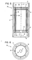
- the device 29 has a cylindrical housing 31 in which a Flow channel 30 with an annular cross section from the cylinder inner wall spaced between radial holding disks 32 and 33 are arranged. At 34 she is Intake opening on the housing 31 and designated 35, the suction opening on the housing 31.
- the flow channel 30 is formed with cylindrical silicone mats 38 and 39, which are inserted in the radial holding disks 32 and 33.
- the holding disc 32 facing the suction opening 34 has for the ring-shaped one Surrounding area of the flow channel pressure compensation bores 36, the even distance between each other on a circle symmetrical to the longitudinal axis X-X of cylindrical housing 31 are arranged.
- the washers 32 and 33 are inserted into one in diameter enlarged inner portion 40 and 41 of the cylindrical housing 31 and lie defined on a shoulder 42 or 43.
- FIG 7 shows a further exemplary embodiment of a device 43 according to the invention for Flow limitation shown at low differential pressures, which are particularly for the Limiting the inhalation volume flow when inhaling therapeutic aerosols is suitable.
- the device 43 consists of a disk-shaped base part 44, in which, as in FIG 8, a disc-shaped recess 45 with integrally formed webs 46 is formed are.
- the webs 46 are formed on a flat bottom 47 of the recess 45 and extend by a height h up to a shoulder 48 which is formed in the base part 44.
- An annular one extends from this shoulder 48, into which the webs 46 merge smoothly Recording projection 49 about the same height h upwards.
- Base part 44 In the exempted part of the Base part 44 are found evenly radially distributed near the outer edge Intake openings 50, which at the outer end of each flow channel 51 between two adjacent webs 46 are arranged.
- the webs 46 are in the embodiment 7 arranged the same length, seen radially from the center of the housing and expand outward in width.
- the differences lie in the fact that it alternates two different webs 46 and 51 evenly spaced apart and pointed to the center are provided tapering, which initially creates a wider flow channel in the center of the Housing 44 is formed, which is then divided radially outwards into two flow channels.
- a thin flexible mat 52 is arranged so that it rests on the webs and extends outwards from a central opening 53 in the mat 52 extends over the shoulder 48 and in the area of the receiving section 49 folded up.
- This thin flexible mat 52 is made of silicone, for example, and is edge-bound a mounting ring 54 clamped to the housing 44.
- the mounting ring 54 is to replace the mat 52 detachable from its frictional fastening position and can be used again.
- the embodiment of the device 43 shown in FIGS. 7 to 10 for Flow limitation works in the same way as the linear version described at the beginning Flow limitation, in which the flow channel is also divided into several flow channels can be done with just one elastic wall or mat.
- the last described Embodiment has a so-called star-shaped structure with several flow channels 51 running in a star shape.
- the flow channels 51 proceed from Center out and are by the said flexible mat 52 on the top, laterally by two star-shaped webs 46 and formed on a lower planar surface 47. Are there the webs 46 and the planar surface 47 are formed in one part.
- the suction port 53 is through an opening in the flexible extending to the inner tips of the webs 46 Mat 52 formed while the suction openings through the lower part of the housing in radial peripheral region are formed.
- the distance h of the elastic mat 52 from the planar is determined by the height h of the webs 46 Area 47 set. Is sucked through the suction opening 53, arises due to the Flow resistance a negative pressure in the formed by the flow channels 51 Flow areas. At the same time, the thin elastic mat 52 is caused by this vacuum pulled into the channel and thereby narrows the cross section of the Flow channel. The deflection of the elastic mat 52 increases with the height of the Vacuum in the flow channel 51 to.
Landscapes
- Health & Medical Sciences (AREA)
- Engineering & Computer Science (AREA)
- Life Sciences & Earth Sciences (AREA)
- Public Health (AREA)
- Anesthesiology (AREA)
- Biomedical Technology (AREA)
- Heart & Thoracic Surgery (AREA)
- Hematology (AREA)
- Bioinformatics & Cheminformatics (AREA)
- Animal Behavior & Ethology (AREA)
- General Health & Medical Sciences (AREA)
- Pulmonology (AREA)
- Veterinary Medicine (AREA)
- Medicinal Preparation (AREA)
- Media Introduction/Drainage Providing Device (AREA)
- External Artificial Organs (AREA)
- Measuring Fluid Pressure (AREA)
- Containers And Packaging Bodies Having A Special Means To Remove Contents (AREA)
- Safety Valves (AREA)
Abstract
Description
- Fig. 1
- eine Draufsicht auf eine Vorrichtung zur Begrenzung des Inhalationsvolumenstroms bei der Inhalation von therapeutischen Aerosolen;
- Fig. 2
- eine Seitenansicht auf die in Fig. 1 gezeigte Vorrichtung;
- Fig. 3
- einen Schnitt entlang der Schnittlinie III-III in Fig. 1;
- Fig. 4
- einen Schnitt entlang der Schnittlinie IV-IV in Fig. 1;
- Fig. 5
- einen Längsschnitt durch ein weiteres Ausführungsbeispiel einer Vorrichtung zur Begrenzung des Inhalationsvolumens bei der Inhalation von therapeutischen Aerosolen;
- Fig. 6
- eine Unteransicht auf die in Fig. 5 gezeigte Vorrichtung;
- Fig. 7
- eine Draufsicht auf ein weiteres Ausführungsbeispiel einer erfindungsgemäßen Vorrichtung zur Flußbegrenzung;
- Fig. 8
- einen Schnitt entlang der Schnittlinie VIII-VIII in Fig. 7;
- Fig. 9
- eine Draufsicht auf eine gegenüber Fig. 7 modifizierte Vorrichtung mit unterschiedlichen Steglängen; und
- Fig. 10
- einen Schnitt entlang der Schnittlinie X-X in Fig. 9.
Claims (26)
- Vorrichtung zur Flußbegrenzung bei niedrigen Differenzdrücken, insbesondere für das Begrenzen des Inhalationsvolumenstroms bei der Inhalation von therapeutischen Aerosolen, bestehend aus
einem Gehäuse (11) mit wenigstens einer Einsaugöffnung (14), wenigstens einer Aussaugöffnung (15) und einem zwischen diesen angeordneten Strömungsbereich (23, 30) mit wenigstens einer flexiblen Wand (18, 20), dessen Querschnitt abhängig von dem zwischen Aussaugöffnung (15) und Einsaugöffnung (14) herrschenden Unterdruck und der Materialflexibilität des Wandmaterials bis zu einer vorbestimmten Größe für einen vorgegebenen maximalen Inhalationsvolumenstrom verringerbar ist. - Vorrichtung nach Anspruch 1,
dadurch gekennzeichnet,
daß der Strömungsbereich wenigstens einen Strömungskanal (23) einen flachen länglichen Querschnitt (a × b) aufweist. - Vorrichtung nach Anspruch 2,
dadurch gekennzeichnet,
daß der Querschnitt jedes Strömungskanals (23) mit gegenüberliegenden großflächigen Wänden (18, 20) gebildet ist. - Vorrichtung nach Anspruch 3, dadurch gekennzeichnet, daß die Wände (18, 20) an ihrer Außenseite wenigstens im Bereich der Mitte zwischen Einsaug- und Aussaugöffnung (14 bzw. 15) zur Umgebung offen (16, 17) sind.
- Vorrichtung nach Anspruch 4,
dadurch gekennzeichnet,
daß jede Wand (18, 20) an ihrer Außenseite wenigstens im Bereich der Mitte zwischen der Einsaug- und Aussaugöffnung (14 bzw. 15) einen Kammerabschnitt (24, 25) aufweist, der über eine Bohrung (16, 17) zur Umgebung geöffnet ist. - Vorrichtung nach einem der vorangehenden Ansprüche,
dadurch gekennzeichnet,
daß jeder Strömungskanal (23) einen schichtweisen Aufbau aufweist. - Vorrichtung nach Anspruch 6,
dadurch gekennzeichnet,
daß jeder Strömungskanal (23) aus einer geschlossenen Wand (20) einer gleich großen rahmenförmigen Zwischenwand (19) und einer gleich großen Wand (18) mit Einsaug- und Aussaugöffnung (21, 22) gebildet ist. - Vorrichtung nach einem der vorangehenden Ansprüche,
dadurch gekennzeichnet,
daß die gegenüberliegenden Wände (18, 20) jedes Strömungskanals (23) randseitig in dem Gehäuse (11) befestigt sind. - Vorrichtung nach einem der vorangehenden Ansprüche,
dadurch gekennzeichnet,
daß das flexible Material, mit dem jeder Strömungskanal (23) gebildet ist, aus bioverträglichem Kunststoff besteht. - Vorrichtung nach einem der vorangehenden Ansprüche,
dadurch gekennzeichnet,
daß wenigstens die großflächigen Kanalwände (18, 20) aus Silikonmatten bestehen. - Vorrichtung nach einem der Ansprüche 6 bis 10,
dadurch gekennzeichnet,
daß die Materialchichten für jeden Strömungskanal (23) zwischen zwei Gehäuseabschnitten (12, 13) austauschbar befestigt sind. - Vorrichtung nach einem der vorangehenden Ansprüche,
dadurch gekennzeichnet,
daß die großflächigen Strömungskanalwände (18, 20) die gleiche Wanddicke aufweisen. - Vorrichtung nach einem der Ansprüche 1 bis 5,
dadurch gekennzeichnet,
daß jeder Strömungskanal einstückig aufgebaut ist. - Vorrichtung nach Anspruch 13,
dadurch gekennzeichnet,
daß jeder Strömungskanal aus einem Silikonbauteil besteht. - Vorrichtung nach einem der Ansprüche 1 bis 3,
dadurch gekennzeichnet,
daß jede Wand (18, 20) an ihrer Außenseite wenigstens im Bereich der Mitte zwischen der Ansaug- und der Aussaugöffnung (14) bzw. (15) einen Kammerabschnitt (24, 25) mit einer Bohrung (16, 17) aufweist, wobei die Bohrungen (16, 17) über einen Kanal bzw. einen Schlauch mit der Einsaugöffnung verbunden sind. - Vorrichtung nach Anspruch 1,
dadurch gekennzeichnet,
daß der Strömungsbereich wenigstens einen Strömungskanal (30) mit einem ringförmigen Querschnitt aufweist. - Vorrichtung nach Anspruch 16,
dadurch gekennzeichnet,
daß jeder Strömungskanal (30) in einem zylinderförmigen Gehäuse (31) symmetrisch und von der Zylinderinnenwand beabstandet zwischen radialen Haltescheiben (32, 33) angeordnet ist. - Vorrichtung nach Anspruch 17,
dadurch gekennzeichnet,
daß die Haltescheiben (32, 33) ringsegmentförmige Ein- und Auslässe (38, 39) aufweisen, wobei die die Einlässe (38) aufweisenden Haltescheiben (32) Druckausgleichsbohrungen (36, 37) für den zylinderförmigen Innenbereich und den ringförmigen Umgebungsbereich jedes Strömungskanals (30) aufweist. - Vorrichtung nach einem der Ansprüche 16 bis 18,
dadurch gekennzeichnet,
daß jeder ringförmige Strömungskanal (30) mit Silikonmatten gebildet ist. - Vorrichtung nach Anspruch 1,
dadurch gekennzeichnet,
daß der Strömungsbereich zwischen einer zentralen Einsaugöffnung (53) und diese radial umgebenden Aussaugöffnungen (50) gebildet ist und sternförmige Stege (46, 51) aufweist, die sich von einer gemeinsamen Bodenfläche (47) zu der flexiblen Wand bzw. Matte (52) erstrecken und Strömungskanäle (51) bilden. - Vorrichtung nach Anspruch 20,
dadurch gekennzeichnet,
daß die Stege (46, 51) unterschiedliche Längen aufweisen. - Vorrichtung nach Anspruch 20 oder 21,
dadurch gekennzeichnet,
daß sich die Stege (46, 51) in ihrer Breite nach außen erweitern. - Vorrichtung nach einem der Ansprüche 20 bis 22,
dadurch gekennzeichnet,
daß zwischen zwei benachbarten Stegen (46, 47) wenigstens eine Ansaugöffnung (50) vorgesehen ist. - Vorrichtung nach einem der Ansprüche 20 bis 23,
gekennzeichnet durch
ein scheibenförmiges Grundteil (44), in dem einstückig zwischen flachen Ausnehmungen (47) die Stege (46, 51) und in den Ausnehmungen (51) randseitig die Aussaugöffnungen (50) gebildet sind, wobei eine dünne flexible Matte (52) mit mittiger Einsaugöffnung (53) auf den Stegen (46, 51) aufliegt und im Randbereich des Grundteils (44) befestigt ist. - Vorrichtung nach Anspruch 24,
dadurch gekennzeichnet,
daß die Matte (52) im Randbereich des Grundteils (44) festgeklebt bzw. festgeschweißt oder mittels eines ringförmigen Montageteils (54) festgeklemmt ist. - Vorrichtung nach Anspruch 24 oder 25,
dadurch gekennzeichnet,
daß die flexible Matte (52) aus Silikon, Silikonkautschuk, Viton, Latex, Naturkautschuk oder anderen Elastomeren besteht.
Applications Claiming Priority (2)
| Application Number | Priority Date | Filing Date | Title |
|---|---|---|---|
| DE19912461A DE19912461B4 (de) | 1999-03-19 | 1999-03-19 | Vorrichtung zur Flußbegrenzung bei niedrigen Differenzdrücken |
| DE19912461 | 1999-03-19 |
Publications (2)
| Publication Number | Publication Date |
|---|---|
| EP1038544A1 true EP1038544A1 (de) | 2000-09-27 |
| EP1038544B1 EP1038544B1 (de) | 2006-06-07 |
Family
ID=7901682
Family Applications (1)
| Application Number | Title | Priority Date | Filing Date |
|---|---|---|---|
| EP00105664A Expired - Lifetime EP1038544B1 (de) | 1999-03-19 | 2000-03-17 | Vorrichtung zur Flussbegrenzung bei niedrigen Differenzdrücken |
Country Status (6)
| Country | Link |
|---|---|
| US (1) | US6681762B1 (de) |
| EP (1) | EP1038544B1 (de) |
| JP (2) | JP4702815B2 (de) |
| AT (1) | ATE328627T1 (de) |
| DE (2) | DE19912461B4 (de) |
| ES (1) | ES2265820T3 (de) |
Cited By (2)
| Publication number | Priority date | Publication date | Assignee | Title |
|---|---|---|---|---|
| EP1163921A1 (de) * | 2000-06-14 | 2001-12-19 | InAMed GmbH | Inhalationsvorrichtung |
| US7891358B2 (en) | 2005-07-06 | 2011-02-22 | Activaero Gmbh | Controllable valve and inhalation device |
Families Citing this family (18)
| Publication number | Priority date | Publication date | Assignee | Title |
|---|---|---|---|---|
| DE10123749A1 (de) | 2001-05-16 | 2002-12-12 | Inamed Gmbh | Vorrichtung zum Verabreichen von Aerosolen |
| EP2022525B1 (de) * | 2007-08-02 | 2012-12-26 | Activaero GmbH | Vorrichtung und System zum Targeting von Aerosolteilchen in einen bestimmten Teil der Lungen |
| JP5570996B2 (ja) | 2007-12-14 | 2014-08-13 | エアロデザインズ インコーポレイテッド | エアロゾル化可能な食料品の送達 |
| EP2344126A1 (de) | 2008-10-14 | 2011-07-20 | Activaero GmbH | Verfahren zur behandlung von copd und anderen lungenerkrankungen |
| US8668901B2 (en) | 2009-02-04 | 2014-03-11 | Activaero Gmbh Research & Development | Use of a glucocorticoid composition for the treatment of severe and uncontrolled asthma |
| US8834848B2 (en) | 2009-02-04 | 2014-09-16 | Activaero Gmbh Research & Development | Flow and volume regulated inhalation for treatment of severe oral corticosteroid-dependent asthma |
| US20100196483A1 (en) * | 2009-02-04 | 2010-08-05 | Activaero Gmbh Research & Development | Method for treatmentof severe and uncontrollable asthma |
| ES2391000T3 (es) | 2009-08-06 | 2012-11-20 | Activaero Gmbh | Dispositivo para la limitación de flujo a presiones diferenciales bajas |
| WO2011038901A1 (en) | 2009-09-29 | 2011-04-07 | Activaero Gmbh | Improved method for treatment of patients with cystic fibrosis |
| BR112012022357B1 (pt) * | 2010-03-04 | 2020-05-05 | Lk Invest Aps | inalador |
| KR101692597B1 (ko) * | 2012-01-31 | 2017-01-03 | 쟈트코 가부시키가이샤 | 자동 변속기의 컨트롤 밸브 바디 구조 |
| US11273271B2 (en) | 2014-07-01 | 2022-03-15 | Aerami Therapeutics, Inc. | Aerosolization system with flow restrictor and feedback device |
| US10471222B2 (en) | 2014-07-01 | 2019-11-12 | Dance Biopharm Inc. | Aerosolization system with flow restrictor and feedback device |
| US10857313B2 (en) | 2014-07-01 | 2020-12-08 | Aerami Therapeutics, Inc. | Liquid nebulization systems and methods |
| CN113616885B (zh) | 2015-12-21 | 2024-06-21 | 3M创新有限公司 | 药用吸入器 |
| US11376379B2 (en) | 2015-12-21 | 2022-07-05 | Kindeva Drug Delivery L.P. | Flow governor assemblies for use in medicinal inhalers |
| JP2019500196A (ja) | 2015-12-21 | 2019-01-10 | スリーエム イノベイティブ プロパティズ カンパニー | 医療用吸入器で使用するための流れ調整器 |
| EP3393517B1 (de) * | 2015-12-22 | 2021-08-11 | AspiAir GmbH | Acetylsalicylsäure zur behandlung von moderater bis schwerer influenza |
Citations (8)
| Publication number | Priority date | Publication date | Assignee | Title |
|---|---|---|---|---|
| US4284505A (en) * | 1979-10-29 | 1981-08-18 | Baxter Travenol Laboratories, Inc. | Flexible membrane filter assembly |
| US4350477A (en) * | 1977-04-20 | 1982-09-21 | Mazal Charles N | Pneumatic pulsatile fluid pump |
| WO1984001293A1 (en) * | 1982-10-01 | 1984-04-12 | Robert E Phillips | Oxygen delivery apparatus |
| US4573640A (en) * | 1976-10-26 | 1986-03-04 | Hydro-Plan Engineering Ltd. | Irrigation emitter unit |
| US4756508A (en) * | 1985-02-21 | 1988-07-12 | Ford Motor Company | Silicon valve |
| EP0341573A2 (de) * | 1988-05-13 | 1989-11-15 | Sartorius Ag | Verfahren und Vorrichtung zur Filtration von Flüssigkeiten im Cross-Flow-Betrieb |
| DE19504750A1 (de) * | 1995-02-14 | 1996-08-22 | Norbert Scherer | Druckausgleichsgefäß |
| US5858569A (en) * | 1997-03-21 | 1999-01-12 | Plug Power L.L.C. | Low cost fuel cell stack design |
Family Cites Families (15)
| Publication number | Priority date | Publication date | Assignee | Title |
|---|---|---|---|---|
| IL45369A0 (en) * | 1974-07-30 | 1974-10-22 | Leyitzur Mamtitim Veavizarei H | A flowrate control device |
| US3966440A (en) * | 1975-06-03 | 1976-06-29 | Catalyst Research Corporation | Colorimetric vinyl chloride indicator |
| ZA77259B (en) * | 1976-03-23 | 1977-11-30 | Mifal Leyitzur Mamtirim Veaviz | A flow rate control device |
| CH627294A5 (en) * | 1977-02-23 | 1981-12-31 | Vaillant Joh Kg | Constant fluid-flow controller |
| US4220281A (en) * | 1979-01-17 | 1980-09-02 | S. C. Johnson & Son, Inc. | Vapor-dispensing device |
| JPS59158460U (ja) * | 1983-04-11 | 1984-10-24 | 東洋エアゾ−ル工業株式会社 | 加圧流体用定量噴射ノズル |
| US4917081A (en) * | 1985-08-05 | 1990-04-17 | Respirator Research, Ltd. | Portable emergency breathing apparatus |
| CA1279042C (en) * | 1986-02-11 | 1991-01-15 | Bespak Plc | Gas pressurised dispensing containers |
| JPS6343071A (ja) * | 1986-08-08 | 1988-02-24 | Moon Star Co | ピンチバルブ |
| US4754751A (en) * | 1987-06-11 | 1988-07-05 | Mine Safety Appliances Company | Escape respirator |
| US5727546A (en) * | 1993-08-18 | 1998-03-17 | Fisons Plc | Powder inhaler with breath flow regulation valve |
| DE4411093A1 (de) * | 1994-03-30 | 1995-10-05 | Reinhard Badewien | Vorrichtung zur Regulierung der Temperatur und Wirkstoffkonzentration inhalierbarer Heil- dämpfe |
| JPH09329251A (ja) * | 1996-06-07 | 1997-12-22 | Paudaringu Japan:Kk | 粉体排出用ダンパー |
| SE9700421D0 (sv) * | 1997-02-07 | 1997-02-07 | Astra Ab | Single dose inhaler I |
| DE19734022C2 (de) * | 1997-08-06 | 2000-06-21 | Pari Gmbh | Inhalationstherapiegerät mit einem Ventil zur Begrenzung des Inspirationsflusses |
-
1999
- 1999-03-19 DE DE19912461A patent/DE19912461B4/de not_active Expired - Fee Related
-
2000
- 2000-03-16 US US09/527,096 patent/US6681762B1/en not_active Expired - Lifetime
- 2000-03-17 EP EP00105664A patent/EP1038544B1/de not_active Expired - Lifetime
- 2000-03-17 AT AT00105664T patent/ATE328627T1/de active
- 2000-03-17 ES ES00105664T patent/ES2265820T3/es not_active Expired - Lifetime
- 2000-03-17 DE DE50012878T patent/DE50012878D1/de not_active Expired - Lifetime
- 2000-03-21 JP JP2000078488A patent/JP4702815B2/ja not_active Expired - Fee Related
-
2008
- 2008-10-04 JP JP2008259145A patent/JP4971280B2/ja not_active Expired - Fee Related
Patent Citations (8)
| Publication number | Priority date | Publication date | Assignee | Title |
|---|---|---|---|---|
| US4573640A (en) * | 1976-10-26 | 1986-03-04 | Hydro-Plan Engineering Ltd. | Irrigation emitter unit |
| US4350477A (en) * | 1977-04-20 | 1982-09-21 | Mazal Charles N | Pneumatic pulsatile fluid pump |
| US4284505A (en) * | 1979-10-29 | 1981-08-18 | Baxter Travenol Laboratories, Inc. | Flexible membrane filter assembly |
| WO1984001293A1 (en) * | 1982-10-01 | 1984-04-12 | Robert E Phillips | Oxygen delivery apparatus |
| US4756508A (en) * | 1985-02-21 | 1988-07-12 | Ford Motor Company | Silicon valve |
| EP0341573A2 (de) * | 1988-05-13 | 1989-11-15 | Sartorius Ag | Verfahren und Vorrichtung zur Filtration von Flüssigkeiten im Cross-Flow-Betrieb |
| DE19504750A1 (de) * | 1995-02-14 | 1996-08-22 | Norbert Scherer | Druckausgleichsgefäß |
| US5858569A (en) * | 1997-03-21 | 1999-01-12 | Plug Power L.L.C. | Low cost fuel cell stack design |
Cited By (2)
| Publication number | Priority date | Publication date | Assignee | Title |
|---|---|---|---|---|
| EP1163921A1 (de) * | 2000-06-14 | 2001-12-19 | InAMed GmbH | Inhalationsvorrichtung |
| US7891358B2 (en) | 2005-07-06 | 2011-02-22 | Activaero Gmbh | Controllable valve and inhalation device |
Also Published As
| Publication number | Publication date |
|---|---|
| JP2009006175A (ja) | 2009-01-15 |
| JP2000288089A (ja) | 2000-10-17 |
| US6681762B1 (en) | 2004-01-27 |
| ATE328627T1 (de) | 2006-06-15 |
| DE19912461A1 (de) | 2000-09-21 |
| EP1038544B1 (de) | 2006-06-07 |
| DE50012878D1 (de) | 2006-07-20 |
| ES2265820T3 (es) | 2007-03-01 |
| JP4971280B2 (ja) | 2012-07-11 |
| DE19912461B4 (de) | 2006-07-20 |
| JP4702815B2 (ja) | 2011-06-15 |
Similar Documents
| Publication | Publication Date | Title |
|---|---|---|
| EP1038544A1 (de) | Vorrichtung zur Flussbegrenzung bei niedrigen Differenzdrücken | |
| DE68914405T2 (de) | Strömungskontrolle. | |
| DE69915262T2 (de) | Blutentnahmevorrichtung | |
| EP1539276B1 (de) | Katheterkopf mit katheterabgang in diskreten drehpositionen | |
| DE2947363A1 (de) | Exhalationsventil | |
| DE60202251T2 (de) | Gerät zur Regelung des Durchflusses medizinischer Flüssigkeiten zu einem Patienten | |
| EP1207969A1 (de) | Entlüftungsvorrichtung bei einem kolben für eine kartusche | |
| EP1449553A1 (de) | Filter für medizinische- und Laborzwecke, insbesondere für Blutanalysen | |
| DE1959679A1 (de) | Filtereinsatz,insbesondere zum Beseitigen von Gas aus einer Stroemung | |
| DE102009005874A1 (de) | Ventil, insbesondere für ein Bauelement der Mikrofluidtechnik | |
| DE102010042265A1 (de) | Ventil, Vorrichtung mit Ventil, Verwendung des Ventils in der Vorrichtung, Mikropumpe mit Ventil, Verneblersystem mit Ventil und Dosier-/Mischvorrichtung mit Ventil | |
| EP1759137B1 (de) | Rückschlagventil | |
| DE102016011597A1 (de) | Richtungsventil, insbesondere für Atemgase, und Verfahren zu dessen Herstellung | |
| EP4644697A1 (de) | Membranpumpe | |
| DE60109859T2 (de) | Pumpeinheit für ein Fluid, insbesondere Blut | |
| EP0679844A2 (de) | Bodenquellauslass aus einem zylindrischen Gehäuse | |
| EP1710481A1 (de) | Membranventil | |
| WO1989002764A1 (fr) | Agencement de clapet antiretour | |
| DE10216220B4 (de) | Unterdruckventil | |
| DE20216791U1 (de) | Luftabscheider | |
| DE3543124A1 (de) | Vorrichtung zur ueberfuehrung einer fluessigkeit | |
| DE69719266T2 (de) | Ölzerstäuber für Druckluft | |
| DE102013114336A1 (de) | Dosierung entnehmbar | |
| DE202006008569U1 (de) | Verbesserte Konstruktion eines Sprenklers | |
| DE4142295C2 (de) | Ventil zur Erzeugung eines Steuerdrucks |
Legal Events
| Date | Code | Title | Description |
|---|---|---|---|
| PUAI | Public reference made under article 153(3) epc to a published international application that has entered the european phase |
Free format text: ORIGINAL CODE: 0009012 |
|
| 17P | Request for examination filed |
Effective date: 20000412 |
|
| AK | Designated contracting states |
Kind code of ref document: A1 Designated state(s): AT BE CH CY DE DK ES FI FR GB GR IE IT LI LU MC NL PT SE |
|
| AX | Request for extension of the european patent |
Free format text: AL;LT;LV;MK;RO;SI |
|
| AKX | Designation fees paid |
Free format text: AT BE CH CY DE DK ES FI FR GB GR IE IT LI LU MC NL PT SE |
|
| 17Q | First examination report despatched |
Effective date: 20031201 |
|
| GRAP | Despatch of communication of intention to grant a patent |
Free format text: ORIGINAL CODE: EPIDOSNIGR1 |
|
| GRAS | Grant fee paid |
Free format text: ORIGINAL CODE: EPIDOSNIGR3 |
|
| GRAA | (expected) grant |
Free format text: ORIGINAL CODE: 0009210 |
|
| AK | Designated contracting states |
Kind code of ref document: B1 Designated state(s): AT BE CH CY DE DK ES FI FR GB GR IE IT LI LU MC NL PT SE |
|
| PG25 | Lapsed in a contracting state [announced via postgrant information from national office to epo] |
Ref country code: IT Free format text: LAPSE BECAUSE OF FAILURE TO SUBMIT A TRANSLATION OF THE DESCRIPTION OR TO PAY THE FEE WITHIN THE PRESCRIBED TIME-LIMIT;WARNING: LAPSES OF ITALIAN PATENTS WITH EFFECTIVE DATE BEFORE 2007 MAY HAVE OCCURRED AT ANY TIME BEFORE 2007. THE CORRECT EFFECTIVE DATE MAY BE DIFFERENT FROM THE ONE RECORDED. Effective date: 20060607 Ref country code: IE Free format text: LAPSE BECAUSE OF FAILURE TO SUBMIT A TRANSLATION OF THE DESCRIPTION OR TO PAY THE FEE WITHIN THE PRESCRIBED TIME-LIMIT Effective date: 20060607 Ref country code: FI Free format text: LAPSE BECAUSE OF FAILURE TO SUBMIT A TRANSLATION OF THE DESCRIPTION OR TO PAY THE FEE WITHIN THE PRESCRIBED TIME-LIMIT Effective date: 20060607 |
|
| REG | Reference to a national code |
Ref country code: GB Ref legal event code: FG4D Free format text: NOT ENGLISH |
|
| REG | Reference to a national code |
Ref country code: CH Ref legal event code: EP Ref country code: CH Ref legal event code: NV Representative=s name: HEPP, WENGER & RYFFEL AG |
|
| REG | Reference to a national code |
Ref country code: IE Ref legal event code: FG4D Free format text: LANGUAGE OF EP DOCUMENT: GERMAN |
|
| REF | Corresponds to: |
Ref document number: 50012878 Country of ref document: DE Date of ref document: 20060720 Kind code of ref document: P |
|
| REG | Reference to a national code |
Ref country code: SE Ref legal event code: TRGR |
|
| PG25 | Lapsed in a contracting state [announced via postgrant information from national office to epo] |
Ref country code: DK Free format text: LAPSE BECAUSE OF FAILURE TO SUBMIT A TRANSLATION OF THE DESCRIPTION OR TO PAY THE FEE WITHIN THE PRESCRIBED TIME-LIMIT Effective date: 20060907 |
|
| GBT | Gb: translation of ep patent filed (gb section 77(6)(a)/1977) |
Effective date: 20060911 |
|
| PG25 | Lapsed in a contracting state [announced via postgrant information from national office to epo] |
Ref country code: PT Free format text: LAPSE BECAUSE OF FAILURE TO SUBMIT A TRANSLATION OF THE DESCRIPTION OR TO PAY THE FEE WITHIN THE PRESCRIBED TIME-LIMIT Effective date: 20061107 |
|
| ET | Fr: translation filed | ||
| REG | Reference to a national code |
Ref country code: ES Ref legal event code: FG2A Ref document number: 2265820 Country of ref document: ES Kind code of ref document: T3 |
|
| PLBE | No opposition filed within time limit |
Free format text: ORIGINAL CODE: 0009261 |
|
| STAA | Information on the status of an ep patent application or granted ep patent |
Free format text: STATUS: NO OPPOSITION FILED WITHIN TIME LIMIT |
|
| 26N | No opposition filed |
Effective date: 20070308 |
|
| PG25 | Lapsed in a contracting state [announced via postgrant information from national office to epo] |
Ref country code: MC Free format text: LAPSE BECAUSE OF NON-PAYMENT OF DUE FEES Effective date: 20070331 |
|
| PG25 | Lapsed in a contracting state [announced via postgrant information from national office to epo] |
Ref country code: GR Free format text: LAPSE BECAUSE OF FAILURE TO SUBMIT A TRANSLATION OF THE DESCRIPTION OR TO PAY THE FEE WITHIN THE PRESCRIBED TIME-LIMIT Effective date: 20060908 |
|
| PG25 | Lapsed in a contracting state [announced via postgrant information from national office to epo] |
Ref country code: LU Free format text: LAPSE BECAUSE OF NON-PAYMENT OF DUE FEES Effective date: 20070317 Ref country code: CY Free format text: LAPSE BECAUSE OF FAILURE TO SUBMIT A TRANSLATION OF THE DESCRIPTION OR TO PAY THE FEE WITHIN THE PRESCRIBED TIME-LIMIT Effective date: 20060607 |
|
| REG | Reference to a national code |
Ref country code: FR Ref legal event code: PLFP Year of fee payment: 17 |
|
| REG | Reference to a national code |
Ref country code: FR Ref legal event code: PLFP Year of fee payment: 18 |
|
| PGFP | Annual fee paid to national office [announced via postgrant information from national office to epo] |
Ref country code: NL Payment date: 20170321 Year of fee payment: 18 |
|
| PGFP | Annual fee paid to national office [announced via postgrant information from national office to epo] |
Ref country code: BE Payment date: 20170321 Year of fee payment: 18 |
|
| REG | Reference to a national code |
Ref country code: FR Ref legal event code: PLFP Year of fee payment: 19 |
|
| REG | Reference to a national code |
Ref country code: NL Ref legal event code: MM Effective date: 20180401 |
|
| REG | Reference to a national code |
Ref country code: BE Ref legal event code: MM Effective date: 20180331 |
|
| PG25 | Lapsed in a contracting state [announced via postgrant information from national office to epo] |
Ref country code: NL Free format text: LAPSE BECAUSE OF NON-PAYMENT OF DUE FEES Effective date: 20180401 |
|
| PG25 | Lapsed in a contracting state [announced via postgrant information from national office to epo] |
Ref country code: BE Free format text: LAPSE BECAUSE OF NON-PAYMENT OF DUE FEES Effective date: 20180331 |
|
| PGFP | Annual fee paid to national office [announced via postgrant information from national office to epo] |
Ref country code: CH Payment date: 20190320 Year of fee payment: 20 Ref country code: IT Payment date: 20190325 Year of fee payment: 20 Ref country code: DE Payment date: 20190329 Year of fee payment: 20 Ref country code: FR Payment date: 20190322 Year of fee payment: 20 Ref country code: GB Payment date: 20190320 Year of fee payment: 20 |
|
| PGFP | Annual fee paid to national office [announced via postgrant information from national office to epo] |
Ref country code: AT Payment date: 20190321 Year of fee payment: 20 Ref country code: SE Payment date: 20190320 Year of fee payment: 20 |
|
| PGFP | Annual fee paid to national office [announced via postgrant information from national office to epo] |
Ref country code: ES Payment date: 20190418 Year of fee payment: 20 |
|
| REG | Reference to a national code |
Ref country code: DE Ref legal event code: R071 Ref document number: 50012878 Country of ref document: DE |
|
| REG | Reference to a national code |
Ref country code: GB Ref legal event code: PE20 Expiry date: 20200316 |
|
| PG25 | Lapsed in a contracting state [announced via postgrant information from national office to epo] |
Ref country code: GB Free format text: LAPSE BECAUSE OF EXPIRATION OF PROTECTION Effective date: 20200316 |
|
| REG | Reference to a national code |
Ref country code: SE Ref legal event code: EUG |
|
| REG | Reference to a national code |
Ref country code: ES Ref legal event code: FD2A Effective date: 20200724 |
|
| REG | Reference to a national code |
Ref country code: AT Ref legal event code: MK07 Ref document number: 328627 Country of ref document: AT Kind code of ref document: T Effective date: 20200317 |
|
| PG25 | Lapsed in a contracting state [announced via postgrant information from national office to epo] |
Ref country code: ES Free format text: LAPSE BECAUSE OF EXPIRATION OF PROTECTION Effective date: 20200318 |