EP1038588A1 - Beschichtungsvorrichtung mit einem rotierenden sprühkopf - Google Patents
Beschichtungsvorrichtung mit einem rotierenden sprühkopf Download PDFInfo
- Publication number
- EP1038588A1 EP1038588A1 EP99970340A EP99970340A EP1038588A1 EP 1038588 A1 EP1038588 A1 EP 1038588A1 EP 99970340 A EP99970340 A EP 99970340A EP 99970340 A EP99970340 A EP 99970340A EP 1038588 A1 EP1038588 A1 EP 1038588A1
- Authority
- EP
- European Patent Office
- Prior art keywords
- atomizing head
- coat film
- rotary atomizing
- semi
- conductive coat
- Prior art date
- Legal status (The legal status is an assumption and is not a legal conclusion. Google has not performed a legal analysis and makes no representation as to the accuracy of the status listed.)
- Withdrawn
Links
Images


Classifications
-
- B—PERFORMING OPERATIONS; TRANSPORTING
- B05—SPRAYING OR ATOMISING IN GENERAL; APPLYING FLUENT MATERIALS TO SURFACES, IN GENERAL
- B05B—SPRAYING APPARATUS; ATOMISING APPARATUS; NOZZLES
- B05B5/00—Electrostatic spraying apparatus; Spraying apparatus with means for charging the spray electrically; Apparatus for spraying liquids or other fluent materials by other electric means
- B05B5/025—Discharge apparatus, e.g. electrostatic spray guns
- B05B5/04—Discharge apparatus, e.g. electrostatic spray guns characterised by having rotary outlet or deflecting elements, i.e. spraying being also effected by centrifugal forces
-
- B—PERFORMING OPERATIONS; TRANSPORTING
- B05—SPRAYING OR ATOMISING IN GENERAL; APPLYING FLUENT MATERIALS TO SURFACES, IN GENERAL
- B05B—SPRAYING APPARATUS; ATOMISING APPARATUS; NOZZLES
- B05B3/00—Spraying or sprinkling apparatus with moving outlet elements or moving deflecting elements
- B05B3/02—Spraying or sprinkling apparatus with moving outlet elements or moving deflecting elements with rotating elements
- B05B3/10—Spraying or sprinkling apparatus with moving outlet elements or moving deflecting elements with rotating elements discharging over substantially the whole periphery of the rotating member
- B05B3/1064—Spraying or sprinkling apparatus with moving outlet elements or moving deflecting elements with rotating elements discharging over substantially the whole periphery of the rotating member the liquid or other fluent material to be sprayed being axially supplied to the rotating member through a hollow rotating shaft
-
- B—PERFORMING OPERATIONS; TRANSPORTING
- B05—SPRAYING OR ATOMISING IN GENERAL; APPLYING FLUENT MATERIALS TO SURFACES, IN GENERAL
- B05B—SPRAYING APPARATUS; ATOMISING APPARATUS; NOZZLES
- B05B5/00—Electrostatic spraying apparatus; Spraying apparatus with means for charging the spray electrically; Apparatus for spraying liquids or other fluent materials by other electric means
- B05B5/025—Discharge apparatus, e.g. electrostatic spray guns
- B05B5/04—Discharge apparatus, e.g. electrostatic spray guns characterised by having rotary outlet or deflecting elements, i.e. spraying being also effected by centrifugal forces
- B05B5/0403—Discharge apparatus, e.g. electrostatic spray guns characterised by having rotary outlet or deflecting elements, i.e. spraying being also effected by centrifugal forces characterised by the rotating member
- B05B5/0407—Discharge apparatus, e.g. electrostatic spray guns characterised by having rotary outlet or deflecting elements, i.e. spraying being also effected by centrifugal forces characterised by the rotating member with a spraying edge, e.g. like a cup or a bell
-
- B—PERFORMING OPERATIONS; TRANSPORTING
- B05—SPRAYING OR ATOMISING IN GENERAL; APPLYING FLUENT MATERIALS TO SURFACES, IN GENERAL
- B05B—SPRAYING APPARATUS; ATOMISING APPARATUS; NOZZLES
- B05B3/00—Spraying or sprinkling apparatus with moving outlet elements or moving deflecting elements
- B05B3/02—Spraying or sprinkling apparatus with moving outlet elements or moving deflecting elements with rotating elements
- B05B3/10—Spraying or sprinkling apparatus with moving outlet elements or moving deflecting elements with rotating elements discharging over substantially the whole periphery of the rotating member
- B05B3/1092—Means for supplying shaping gas
-
- B—PERFORMING OPERATIONS; TRANSPORTING
- B05—SPRAYING OR ATOMISING IN GENERAL; APPLYING FLUENT MATERIALS TO SURFACES, IN GENERAL
- B05B—SPRAYING APPARATUS; ATOMISING APPARATUS; NOZZLES
- B05B5/00—Electrostatic spraying apparatus; Spraying apparatus with means for charging the spray electrically; Apparatus for spraying liquids or other fluent materials by other electric means
- B05B5/025—Discharge apparatus, e.g. electrostatic spray guns
- B05B5/04—Discharge apparatus, e.g. electrostatic spray guns characterised by having rotary outlet or deflecting elements, i.e. spraying being also effected by centrifugal forces
- B05B5/0426—Means for supplying shaping gas
Definitions
- This invention relates to a rotary atomizing head type coating machine which is adapted to atomize a paint into finely divided particles by high speed rotation of a rotary atomizing head, and more particularly to a rotary atomizing head type coating machine which is suitable for use as a direct charging type electrostatic coating machine which is adapted to apply a high voltage directly to paint.
- a rotary atomizing head type coating machine is largely constituted by a cover of a tubular shape, an air motor which is housed in the tubular cover, a hollow rotational shaft which is passed axially through and rotated by the air motor, a feed tube which is extended axially and internally of the hollow rotational shaft, and a rotary atomizing head which is mounted on the rotational shaft and put in high speed rotation to spray a paint which is supplied from the feed tube.
- the rotary atomizing head is formed of an insulating synthetic resin material, and a semi-conductive film layer is formed at and on paint releasing edges of the rotary atomizing head.
- a high voltage is applied to the semi-conductive film layer through a semi-conductive film, an electrode or the like which is provided in the proximity of the rotary atomizing head.
- corona discharge occurs at the fore end of the semi-conductive film layer of the rotary atomizing head, and aeroions are generated by aeroionization under the influence of the corona discharge.
- the paint particles which are sprayed from the paint releasing edges of the rotary atomizing head are adsorbed on aeroions, which are generated in a corona discharge zone, to form charged paint particles. Consequently, charged paint particles which are sprayed from the rotary atomizing head are urged to fly along an electrostatic field toward and deposit on a coating object which is held at the earth potential.
- the prior art rotary atomizing head type coating machines employ a rotary atomizing head which is formed of an insulating synthetic resin material. Accordingly, when a coating object to be coated comes to an abnormally close proximity to the rotary atomizing head, there is little possibility that spark discharges generally referred to as “streamers” or “sparks” are induced solely by accumulated charges on the part of the rotary atomizing head.
- the coating machine has metallic parts such as air motor, which have a floating capacitance and therefore can store electric charges therein. If electric charges are stored by the floating capacitance of the air motor or other metallic parts, spark discharges take place as a result of instant discharge of the stored electric charges to the coating object.
- Discharges from the air motor can also be prevented, for example, by inserting a high resistance between the air motor and a high voltage generator in such a way as to lower the voltage to be applied to the air motor.
- a reduction in application voltage to the air motor will lead to a reduction in paint particle charging rate and as a result to a reduction in paint deposition efficiency.
- a rotary atomizing head type coating machine which comprises: a cover of a tubular shape formed of an insulating synthetic resin material; an air motor mounted within the cover and formed of a conducting metallic material; a rotational shaft formed of an, insulating material passed axially through and rotated by the air motor; a rotary atomizing head formed of an insulating synthetic resin material in a bell-like shape having a mounting portion at a rear end and paint releasing edges at a fore end thereof, and mounted on the rotational shaft at an axially spaced position from a fore end of the air motor; an on-head semi-conductive coat film provided on outer peripheral surfaces of the rotary atomizing head for charging paint particles to be sprayed from the rotary atomizing head; a power supply semi-conductive coat film provided either on inner peripheral surfaces of the cover or on outer peripheral surfaces of the rotational shaft between the fore end of the air motor and a rear end of the
- a high voltage which is applied to the air motor is supplied to the on-head semi-conductive coat film on the rotary atomizing head of an electrically insulating material through the power supply semi-conductive coat film which is provided either on inner peripheral surfaces of the cover or on outer peripheral surfaces of the rotational shaft.
- the rotational shaft is formed of an insulating material, it becomes possible to prevent shortcircuiting between the rotational shaft and a coating object even when the rotary atomizing head is brought to an abnormally close proximity to the coating object.
- the provision of the first arcuately curved portion between the fore distal end of the air motor and the power supply semi-conductive coat film, and of the second arcuately curved portion between the power supply semi-conductive coat film and the rear end of the on-head semi-conductive coat film makes it possible to prevent occurrence of spark discharges (streamer discharges) between the fore end of the air motor and the rear end of the rotary atomizing head, even when the rotary atomizing head comes to an abnormally close proximity to a coating object to permit a large current to flow from the air motor to the paint releasing edges.
- the rotational shaft is formed of an insulating ceramic material.
- This arrangement contributes to increase the mechanical strength of the rotational shaft to a significant degree as compared with a rotational shaft which is formed of a synthetic resin material in general or of a filler synthetic resin material or the like as disclosed in Japanese Laid-Open Patent Publication No. H6-269701.
- a rotational shaft which is formed of a synthetic resin material in general or of a filler synthetic resin material or the like as disclosed in Japanese Laid-Open Patent Publication No. H6-269701.
- the first and second arcuately curved portions are formed to have arcuately curved surfaces of from 0.5mm to 25mm in radius of curvature.
- This arrangement contributes to prevent concentration of an electric field effectively even when the rotary atomizing head is abruptly brought to an abnormally close proximity to a coating object, as compared with a case where the arcuately curved portions have a radius of curvature smaller than 0.5mm. Consequently, an electric field is distributed in a dispersed way on each arcuately curved portion, and prevented from giving rise to spark discharges which might lead to ignition.
- the first and second arcuately curved portions are spaced away from each other by a distance of from 10mm to 80mm.
- the first and second arcuately curved portions serve to moderate concentration of electric field at these portions, even when a coating object suddenly comes to an abnormally close proximity.
- electrical discharges from the air motor to the rotary atomizing head can be controlled to a moderate level.
- the first arcuately curved portion is formed of an insulating synthetic resin material and applied with a semi-conductive coat film on outer peripheral surfaces thereof.
- the first arcuately curved portion which is in the shape of a doughnut serves to prevent concentration of electrical charges at the fore end of the air motor.
- the second arcuately curved portion is formed of an insulating synthetic resin material and applied with a semi-conductive coat film on outer peripheral surfaces thereof.
- a high voltage which is applied to the air motor is supplied to the second arcuately curved portion through the power supply semiconductive coat film. Then, through the second arcuately curved portion, the high voltage is supplied to the on-head semi-conductive coat film which is on the outer peripheral surfaces of the rotary atomizing head.
- the first arcuately curved portion is formed of a conducting metallic material.
- the first arcuately curved portion which is in the shape of a doughnut serves to prevent concentration of electric field at the fore end of the air motor.
- the second arcuately curved portion is formed of a conducting metallic material.
- a high voltage which is applied to the air motor is supplied to the second arcuately curved portion through the power supply semi-conductive coat film. Then, through the second arcuately curved portion, the high voltage is supplied to the semi-conductive coat film on the rotary atomizing head.
- the first and second arcuately curved portions are formed of the same material as the cover and applied with a semi-conductive coat film on outer peripheral surfaces thereof.
- a high voltage which is applied to the air motor is supplied to the power supply semi-conductive coat film through the first arcuately curved portion, and then from the power supply semi-conductive coat film to the second arcuately curved portion. From the second arcuately curved portion, the high voltage is then supplied to the on-head semi-conductive coat film on the rotary atomizing head.
- a power supply semi-conductive coat film is provided on outer peripheral surfaces of the rotational shaft, and an on-head semi-conductive coat film is provided on outer peripheral surfaces of a rotary atomizing head of an insulating synthetic resin material, while a first arcuately curved portion is provided at the fore end of the air motor and a second arcuately curved portion is provided on the side of a rear end portion of the on-head semi-conductive coat film.
- a power supply semi-conductive coat film is provided on inner peripheral surfaces of the cover, and an on-head semi-conductive coat film is provided on outer peripheral surfaces of the rotary atomizing head, while a first arcuately curved portion is provided at the fore end of the air motor, and a second arcuately curved portion is provided on the side of a rear end portion of the on-cup semi-conductive coat film.
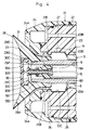
- FIGs. 1 to 3 there is shown a rotary atomizing head type coating machine according to a first embodiment of the present invention.
- cover 1 which determines the outer configuration of the rotary atomizing head type coating machine.
- the cover 1 is constituted by a cover tube 2 which is formed substantially in a cylindrical shape, a motor support case 3, and a shaping air ring 4.
- the motor support case 3 is formed in the shape of a thick cylindrical tube and securely attached to the inner periphery of the cover tube 2.
- the motor support case 3 is provided with a stepped hollow support cavity 3A to support an air motor 5 which will be described hereinafter. Bored around the hollow support cavity 3A are shaping air passages 3B which are extended in the axial direction.
- the shaping air ring 4 is attached to the front side of the motor support case 3, and has air outlet holes 4A arranged annularly on the front side thereof. Shaping air is supplied to each one of the air outlet holes 4A through the shaping air passages 3B.
- cover tube 2, motor support case 3 and shaping air ring 4 are formed of an insulating synthetic resin material such as polytetrafluoroethylene (PTFE), polyethylene terephthalate (PET) or the like.
- PTFE polytetrafluoroethylene
- PET polyethylene terephthalate
- the air motor 5 includes a motor body 6 which is formed of a conductive metallic material in a stepped cylindrical shape, an air turbine 7 which is accommodated in the motor body 6, and a static air bearing 8 which rotatably supports a rotational shaft 9 as will be described hereinafter.
- the motor body 6 is constituted by a turbine receptacle portion 6A of a larger diameter which accommodates the air turbine 7 therein, and an air bearing receptacle portion 6B of a smaller diameter which is extended axially forward from the turbine receptacle portion 6A.
- the static air bearing 8 is provided on and around the inner periphery of the air bearing receptacle portion 6B.
- a hollow bore 6C which is extended forward from the turbine receptacle portion 6A and across the air bearing portion 6B to receive a rotational shaft 9 therein.
- a high voltage between -60kv and - 120kv is applied to the motor body 6 from a high voltage generator (not shown).
- the motor body 6 is fitted in the hollow support cavity 3A, and the rotational shaft 9 which is projected from the motor body 6 is positioned forward of a fore distal end of the hollow support cavity 3A.
- the rotational shaft 9 is formed, for example, of a hard ceramic material or the like, and passed axially through the motor body 6 and supported by the static air bearing 8 in such a way as to permit high speed rotation therein.
- an axially extending bore 9A to receive therein a feed tube 10 which will be described after.
- Proximal base end of the rotational shaft 9 is securely fixed to the air turbine 7 of the air motor 5, while its fore end is projected forward of the motor body 6.
- a male screw portion 9B for threaded engagement with a female screw portion 12F of a rotary atomizing head body 12 which will be described after.
- the feed tube 10 is the feed tube which is extended axially through the internal bore 9A of the rotational shaft 9 and the fore end of the feed tube 10 is projected from the rotational shaft 9 and extended into the rotary atomizing head 11 to supply paint or thinner to the rotary atomizing head 11.
- the feed tube 10 is constituted by a double wall tube, providing a paint passage within an inner tube 10A and a thinner passage between the inner tube 10A and an outer tube 10B.
- a check valve 10C formed a rubber or the like is attached to the fore end of the outer tube 10B to prevent thinner from dripping off the feed tube 10.
- the feed tube 10 is formed of an insulating synthetic resin material such as polyether sulfone (PES), polyphenylene sulfide (PPS), polyether imide (PEI), polyether ether ketone (PEEK), polyoxymethylene (POM), polyamide imide (PAI), polyethylene terephthalate (PET), polyimide (PI) and the like.
- PES polyether sulfone
- PPS polyphenylene sulfide
- PEI polyether imide
- PEEK polyether ether ketone
- POM polyoxymethylene
- PAI polyamide imide
- PET polyethylene terephthalate
- PI polyimide
- rotary atomizing head 11 which is of the bell-, cup- or saucer-type and mounted on the rotational shaft 9 on the front side of the shaping air ring 4.
- This rotary atomizing head 11 is constituted by an atomizing head body 12 and a hub member 13.
- the atomizing head body 12 which determines the configuration of the rotary atomizing head 11 is formed of an insulating synthetic resin material, for example, polyether sulfone (PES), polyphenylene sulfide (PPS), polyether imide (PEI), polyether ether ketone (PEEK), polyoxymethylene (POM), polyamide imide (PAI), polyethylene terephthalate (PET), polyimide (PI) or the like, and formed in a bell-shape which is diverged in the forward direction.
- PES polyether sulfone
- PPS polyphenylene sulfide
- PEI polyether imide
- PEEK polyether ether ketone
- POM polyoxymethylene
- PAI polyamide imide
- PET polyethylene terephthalate
- PI polyimide
- the atomizing head body 12 is largely constituted by a forwardly diverging bell cup portion 12A, a cylindrical mounting portion 12B which is extended out on the rear side of the bell cup portion 12A, an annular partition wall 12C which is located behind the above-mentioned hub member 13 and projected radially inward between the bell cup portion 12A and the mounting portion 12B, a paint spreading surface 12D which is formed on the front side of the bell cup portion 12A forward of the hub member 13 to spread a paint into a thin film, paint releasing edges 12E which is provided at the front end of the bell cup portion 12A to release a paint therefrom in the form of liquid threads, a female screw portion 12F which is provided on the inner peripheral side of the mounting portion 12B for threaded engagement with the above-mentioned male screw portion 9B on the part of the rotational shaft 9, a stepped or recessed hub mounting portion 12G into which the hub member 13 is threaded, and an annular groove 12H which is formed on a rear end face of the mounting portion
- the hub member 13 which is threaded into the stepped hub mounting portion 12G of the bell head 12A is formed of an insulating synthetic resin material similar to the atomizing head body 12, and constituted by a circular disk portion 13A and a cylindrical body portion 13B which is axially extended to the rear side of the circular disk portion 13A.
- a large number of first hub holes 13C which serve as paint outlet holes for guiding a paint or thinner from the feed tube 10 toward the paint spreading surface 12D of the atomizing head body 12.
- Formed in center portions of the circular disk 13A are a plural number of second hub holes 13D (only two of which are shown in the drawings) which serve as thinner outlet holes which supplies thinner to the front side of the atomizing head.
- a fore end portion of the rotational shaft 9 is fitted into the mounting portion 12B of the atomizing head body 12 and the female screw portion 12F on the part of the atomizing head 12 is threadedly engaged with the male screw portion 9B on the part of the rotational shaft 9. Consequently, the rotary atomizing head 11 is securely mounted on the rotational shaft 9. Further, the rear end face of the mounting portion 12B of the atomizing head body 12 (i.e., the surface with the annular groove 12H) is spaced from the fore end face 6D of the air bearing 6B constituting the motor body 6, for example, at a distance in the range of 10mm to 80mm.
- Indicated at 14 is an on-head semi-conductive coat film which is applied on outer peripheral surfaces of the rotary atomizing head 11.
- This on-head semi-conductive coat film 14 is formed by applying a synthetic resin material such as polyester, epoxy resin, fluorine resin or the like into which carbon fiber or other metallic or conductive fiber is kneaded.
- the on-head semi-conductive coat film 14 is formed on outer peripheral surfaces between the rear end of the mounting portion 12B to the paint releasing edges 12E of the atomizing head body 12.
- the semi-conductive coat film 14 is held in contact with an arcuate second coat film 18 on the circumference of a limiter ring 17 which will be described hereinafter, and, in fore end portions on the side of the paint releasing edges 12E, the on-head semi-conductive coat film 14 is allowed to contact the paint to be released from the paint releasing edges 12E.
- the rotary atomizing head 11 is arranged to have a electrostatic capacitance which is smaller than 0.059pF. As a consequence, the electrostatic charge build-up on the rotary atomizing head 11 can be held to a level which is low enough to prevent occurrence of spark discharges between the rotary atomizing head 11 and a coating object.
- the first limiter ring 15 which forms a first arcuately curved portion at the fore end of the air motor 5.
- the limiter ring 15 is formed in a circular ring-like shape in section by the use of an insulating synthetic resin material similar to the atomizing head body 12, and securely fixed to a fore end face 6D of the motor body 6.
- a first arcuate coat film 16 is formed on the outer periphery of the limiter ring 15.
- the first arcuate coat film 16 is formed by application of a synthetic resin material such as polyester, epoxy resin, fluorine resin or the like into which conductive fiber is kneaded, and located in a position intermediate between the air motor 5 and a power supply semi-conductive coat film 19 which will be described hereinafter. Further, including the arcuate coat film 16, the surface of the first limiter ring 15 is arranged to have a radius of curvature of approximately 0.5 mm to 25 mm.
- Denoted at 17 is a second limiter ring which is provided at the rear end of the rotary atomizing head 11 as a second arcuately curved portion.
- the second limiter ring 17 is formed in a circular ring-like shape in section by the use of an insulating synthetic resin material, and fitted in an annular groove 12H which is formed on a rear end face of the mounting portion 12B of the atomizing head body 12.
- Formed on surfaces of the limiter ring 17 is a second arcuate coat film 18 as a second arcuately curved portion.
- the second arcuate coat film 18 is formed by application of a semi-conductive film similarly to the first arcuate coat film 16, and located between and electrically connected to the semi-conductive coat film 14 on the atomizer body and the semi-conductive coat film 19 for the power supply which will be described hereinafter.
- the first and second limiter rings 15 and 16 are spaced away from each other, by a distance L in the range of 10 mm to 80 mm, for example about 50mm. Further, including the arcuate coat film 18, the surface of the second limiter ring 17 is formed to have a radius of curvature of approximately 0.5mm to 25mm.
- the power supply semi-conductive coat film which is applied on outer peripheral surfaces of the rotational shaft 9.
- This power supply semi-conductive coat film 19 is formed by application of a synthetic resin material such as polyester, epoxy resin, fluorine resin or the like into which carbon fiber or metallic or other conductive fiber is kneaded, similarly to the second arcuate coat film 18. Further, the power supply semi-conductive coat film 19 is located between the fore end of the motor body 6 and the rear end of the mounting portion 12B, and held in contact with the arcuate coat film 18 at its fore end.
- the rear end of the power supply conductive coat film 19 is located in the vicinity of the motor body 6, more specifically, located in such small gap relation with the fore end face 6D of the motor body 6 as to permit air discharge thereacross. Therefore, the power supply semi-conductive coat film 19 is electrically connected with the first arcuate coat film 16 through a small gap, and, as the rotational shaft 9 is put in high speed rotation, the power supply semi-conductive coat film 19 is kept out of direct contact with the motor body 6 to prevent its frictional wear.
- the first arcuate coat film 16, power supply semi-conductive coat film 19, second arcuate coat film 18 and the semi-conductive coat film 19 on the atomizing head are electrically connected with each other between the air motor 5 and the rotary atomizing head 11. It follows that a high voltage which is applied to the motor body 6 is supplied to the paint releasing edges 12E of the rotary atomizing head 11 via the first arcuate coat film 16, power supply semi-conductive coat film 19, second arcuate coat film 18 and on-head semi-conductive coat film 14.
- resistance values of the first arcuate coat film 16, power supply semi-conductive coat film 19, second arcuate semi-conductive coat film 18 and on-head semi-conductive coat film 14 are determined arbitrarily in such a way that the resistance between the fore end face 6D of the motor body 6 and the paint releasing edges 12E of the rotary atomizing head 11 falls in a range of 20 M ⁇ to 100 M ⁇ .
- the rotary atomizing head type coating machine with the above-described arrangements according to the present embodiment is operated in the manner as described below.
- the coating machine is used for coating a vehicle body or the like, for example, air is supplied to the air motor 5 in the first place, actuating the air turbine 7 to put the rotary atomizing head 11 in high speed rotation along with the rotational shaft 9. In this state, paint is supplied to the feed tube 10 and then to the rotary atomizing head 11 from the feed tube 10.
- the paint which has been supplied to the rotary atomizing head 11 is allowed to flow out onto the paint spreading surface 12D on the atomizing head body 12 through the hub holes 13C of the hub member 13 and spread into the shape of a thin film, and released forward in the form of atomized paint particles from the paint releasing edges 12E.
- the high voltage which is applied to the motor body 6 of the air motor 5 is supplied to the rotary atomizing head 11 through the first arcuate coat film 16, power supply semi-conductive coat film 19, second arcuate coat film 18 and on-head semi-conductive coat film 14.
- corona discharge takes place on the side of the paint releasing edges 12E at the fore end of the semi-conductive coat film 14 on the rotary atomizing head 11, and, for example, negative ion is produced in case a negative electric field is formed in the vicinity of the on-head semi-conductive coat film 14.
- paint particles come into contact with the on-head semi-conductive coat film 14 and as a result the surfaces of paint particles are imparted with the opposite potential by inductive polarization. That is to say, in case of a negative electric field, the surfaces of paint particles are imparted with a positive potential. Therefore, as paint particles are sprayed from the paint releasing edges 12E, negative aeroions which are generated in a corona discharge region are adsorbed on the sprayed paint particles to negatively charge the same.
- paint particles which are sprayed by the rotary atomizing head 11 are turned into charged paint particles, and undergo further atomization in shaping air streams which are spurted out through the air outlet holes 4A and put on flight toward a coating object which is connected to the earth potential, traveling along an electrostatic field which is formed between the rotary atomizing head and the coating object.
- the rotary atomizing head type coating machine of the present embodiment can spray coating objects substantially in the same manner as prior art counterparts.
- the rotary atomizing head 11 is formed of an insulating synthetic resin material and provided with the on-head semi-conductive coat film 14 on its outer periphery. Therefore, even if the coating machine is abruptly brought to an abnormally close proximity to a coating object during a coating operation (a near miss), the discharge energy E can be suppressed to a low level as the floating capacitance of the air motor 5 is converted into distributed capacitance by resistance of the on-head semi-conductive coat film 14 and other associated parts. Therefore, spark discharge would not occur even in the event of short circuiting due to a near miss or a contact with a coating object by the rotary atomizing head 11.
- the rotational shaft 9 and feed tube 10 are formed of an insulating material, the arrangements of the present embodiment contribute to preclude the possibility of short circuiting between the rotational shaft 9 and a coating object, even when the rotary atomizing head 11 is brought to an abnormally close to the coating object, thereby enhancing the safety and reliability of operation.
- the rotary atomizing head 11 approaches to an abnormally close proximity to a coating object abruptly, it is generally observed that there is a tendency of an electric field concentrating on the fore end face 6D of the motor body 6 and the rear end face of the mounting portion 12B which are usually shaped in a relatively projected form, thereby giving rise to spark discharge which might lead to ignition.
- the first and second limiter rings 15 and 17 of doughnut-like shapes which are covered with the arcuate coat films 16 and 18 are provided on the fore end face 6D of the motor body 6 and on the rear end face of the mounting portion 12B of the rotary atomizing head body 12, respectively.
- the electric field is dispersed over the curved surface of the arcuate coat film 16 on the first limiter ring 15.
- the electric field is dispersed over its curved surface.
- the first limiter ring 15 functions to moderate the concentration of electric field on the fore end face 6D of the air motor 5.
- the second limiter ring 17 functions to moderate concentration of electric field at the rear end of the rotary atomizing head 11.
- the high voltage on the side of the air motor 5 can be smoothly supplied to the rotary atomizing head 11 through the first arcuate coat film 16, power supply semi-conductive coat film 19, second arcuate coat film 18 and on-head semi-conductive coat film 14. Therefore, the high voltage to be supplied to the paint releasing edges 12E of the rotary atomizing head 11 can be dropped in a reliable manner through the first arcuate coat film 16, power supply semi-conductive coat film 19, second arcuate coat film 18 and on-head semi-conductive coat film 14, thereby precluding the possibilities of spark discharges occurring between the rotary atomizing head 11 and a coating object even when the rotary atomizing head 11 is abruptly brought to a close proximity to the coating object.
- the high voltage on the side of the paint releasing edges 12E of the rotary atomizing head 11 can be dropped in a secure and reliable manner through the first arcuate coat film 16, power supply semi-conductive coat film 19, second arcuate coat film 18 and on-head semi-conductive coat film 14. Therefore, when the rotary atomizing head 11 is in operation for spraying a coating object from a distance of about 30cm. for example. almost no current flows between the rotary atomizing head 11 and the coating object. This means that it is possible to maintain a high deposition rate since no drops occur to the high voltage to be supplied to the rotary atomizing head 11.
- the rotational shaft 9 is formed of insulating ceramic material, it has higher mechanical strengths as compared with rotational shafts which are made of either an ordinary synthetic resin material or a filler synthetic resin material. This makes it possible to prevent deformations of the rotational shaft 9 which is put in high speed rotation during operation, and therefore to improve the reliability of the air motor 5.
- electrical insulation strength of the rotational shaft 9 can be enhanced by reduction of moisture absorption, for the purpose of preventing electric charges accumulated on the air motor 5 form being discharged instantly to a coating object through the rotational shaft 9.
- the limiter rings 15 and 17, including the respective arcuate coat films 16 and 18, are arranged to have a radius of curvature of about 0.5 mm to 25 mm. Therefore, even in case the rotary atomizing head 11 is abruptly brought to a close proximity to a coating object, they can prevent concentration of electric field on the fore end face 6D of the air motor 5 and on the rear end of the rotary atomizing head 11 far more effectively than in a case where the radius of curvature r is smaller than 0.5 mm.
- This arrangement contributes to moderate concentration of an electric field by distributing same in a dispersed fashion over the arcuate coat films 16 and 18 on the curved surfaces of the limiter rings 15 and 17, respectively. Besides, as compared with a case where the radius of curvature r is larger than 25 mm, it becomes possible to minimize the diameter of the cover 1 and to downsize the coating machine itself to a significant degree.
- first and second limiter rings 15 and 17 are spaced away from each other by a distance in the range of 10mm to 80mm. Therefore, even when the rotary atomizing head 11 is brought to an abnormally close proximity to a coating object abruptly, the first and second limiter rings 15 and 17 can function to moderate concentration of electric field more effectively than in a case where they are located at a smaller distance from each other, i.e., at a distance smaller than 10mm. Therefore, in the event of electrical discharge form the air motor 5 to the rotary atomizing head 11, if any, it can be controlled to a moderate level to prevent occurrence of spark discharges. In addition, as compared with a case where the first and second limiter rings 15 and 17 are located at a distance farther than 80mm from each other, it becomes possible to downsize the coating machine itself.
- FIG. 4 there is shown a second embodiment of the present invention.
- This second embodiment has a feature in that a power supply semi-conductive coat film is provided on the inner periphery of the cover.
- those component parts which are common with the foregoing first embodiment are designated by common reference numerals or characters to avoid repetitions of same explanations.
- the cover 21 is a cover which determines the outer configuration of the rotary atomizing head type coating machine.
- the cover 21 is constituted by a cover tube 22 which is formed substantially in a cylindrical shape, a motor support case 23, and a shaping air ring 24.
- the motor support case 23 is generally in the shape of a thick-walled cylinder formed of an insulating synthetic resin material. Bored into or through the support case 23 are a hollow support cavity 23A and a shaping air passage 23B. However, this motor support case 23 differs from the motor support case 3 of the first embodiment in that an annular groove 23C is formed internally around a fore end portion of the hollow support cavity 23A.
- first and second arcuately protruding ridge portions 23D and 23E are formed around axially rear and fore end portions of the internal annular groove 23C, respectively.
- the fore end face 6D of the motor body 6 is positioned in the vicinity of the first arcuately protruding ridge portion 23D, while the rear end of the rotary atomizing head 28, which will be described hereinafter, is located in the vicinity of the second arcuately protruding ridge portion 23E.
- Surfaces of the first and second arcuately protruding ridge portions 23D and 23E have a radius of curvature r of approximately 5 mm to 25 mm, including arcuate coat films 25 and 26 which will be described below.
- first arcuate coat film which is formed on the surface of the first arcuately protruding ridge portion 23D.
- this arcuate coat film 25 is formed of a synthetic resin material such as polyester, epoxy resin, fluorine resin or the like which has conducting fiber kneaded thereinto.
- the arcuate coat film 25 is extended into the internal annular groove 23C from a fore end portion of the air motor body 6 and electrically connected to the fore end face 6D of the air motor body 6.
- Designated at 26 is a second arcuate coat film which is formed on the surface of the second arcuately protruding ridge portion 23E.
- this second arcuate coat film 26 is formed of a synthetic resin material such as polyester, epoxy resin, fluorine resin or the like which has conductive fiber kneaded thereinto, and electrically connected to the motor body 6 through a power supply semi-conductive coat film 27 which will be described hereinafter.
- the arcuate coat film 26 is located in such small gap relation with the rear end of a rotary atomizing head 28, which will be described after, as to permit air discharge thereacross.
- the power supply semi-conductive coat film 27 is a power supply semi-conductive coat film which is applied on the surface of the annular groove 23C of the motor support case 23.
- the power supply semi-conductive coat film 27 is formed of a synthetic resin material such as polyester, epoxy resin, fluorine resin or the like having conductive fiber kneaded thereinto, and arranged to cover substantially the entire inner peripheral surfaces of the annular groove 23C. Further, the power supply semi-conductive coat film 27 is held in contact with the arcuate coat films 25 and 26 at its opposite axial ends. Consequently, the power supply semi-conductive coat film 27 electrically connected to the air motor body 6 along with the arcuate coat films 25 and 26.
- a rotary atomizing head which is rotatably mounted on a fore end portion of the rotational shaft 9.
- This rotary atomizing head 28 is constituted by an atomizing head body 29 and a hub member 30.
- the atomizing head body 29 of this embodiment is provided with a bell cup portion 29A, a mounting portion 29B, an annular partition wall 29C, a paint spreading surface 29D, paint releasing edges 29E, a female screw portion 29F, and a stepped hub mount portion 29G, which are all formed of an insulating synthetic resin material.
- the atomizing head body 29 differs from the atomizing head body 12 of the first embodiment in that no limiter ring is attached to the rear end of the mounting portion 29B.
- the hub member 30 of this embodiment is constituted by a circular disk portion 30A and a cylindrical body portion 30B, and bored with a large number of first and second hub holes 30C and 30D.
- Indicated at 31 is an on-head semi-conductive coat film which is formed on outer peripheral surfaces of the atomizing head body 29.
- the on-head semi-conductive coat film 31 is formed in a substantially same manner as the on-head semi-conductive coat film 14 in the first embodiment, and applied on surfaces between the paint releasing edges 29E and the rear end of the mounting portion 29B of the atomizing head body 29.
- the on-head semi-conductive coat film 31 is disposed in small gap relation with the second arcuate coat film 26.
- a high voltage which is applied to the air motor 5 is supplied to the second arcuate coat film 26 through the first arcuate coat film 25 and the power supply semi-conductive coat film 27, and at the same time supplied to the on-head semi-conductive coat film 31 by air discharge across the gap space between the on-head semi-conductive coat film 31 and the second arcuate coat film 26. Therefore, through the on-head semi-conductive coat film 31, a high voltage can be applied to paint particles which are released from the paint releasing edges 29E.
- resistance values of the first arcuate coat film 25, power supply semi-conductive coat film 27, second arcuate coat film 26 and on-head semi-conductive coat film 31 are preadjusted such that a resistance value between the fore end face 6D of the motor body 6 and the paint releasing edges 29E of the rotary atomizing head 28 falls in a range of from 20 M ⁇ to 100 M ⁇ .
- the present embodiment can produce substantially the same operational effects as the foregoing first embodiment.
- the on-head semi-conductive coat film 31 can be located at a spaced position from the rotational shaft 9 because there is no necessity for contacting the on-head semi-conductive coat film 31 with the rotational shaft 9. Therefore, the rotary atomizing head 28 can be easily dismantled from the rotational shaft 9 to facilitate a washing operation or other jobs on the rotary atomizing head in maintenance and service.
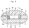
- a third embodiment of the present invention has a feature in that, in place of the first limiter ring 15 and the first arcuate coat film 16 of the foregoing first embodiment, a first arcuately curved portion is formed by the use of a limiter ring of conductive metallic material.
- a limiter ring of conductive metallic material in place of the first limiter ring 15 and the first arcuate coat film 16 of the foregoing first embodiment, a first arcuately curved portion is formed by the use of a limiter ring of conductive metallic material.
- first limiter ring which is provided on the fore end face 6D of the motor body 6 as a first arcuately curved portion.
- This limiter ring 41 is formed in a circular ring-like shape in cross-section by the use of conductive metallic material. Further, the limiter ring 41 is provided in at a position intermediate between the power supply semi-conductive coat film 19 and the air motor 5, in such small gap relation with the rear end of the power supply semi-conductive coat film 19 as to permit air discharge across an intervening gap space.
- the surface of the first limiter ring 41 is formed to have a radius of curvature of approximately 0.5mm to 25mm.
- a first arcuate coat film 42 similar to the arcuate coat film 16 in the first embodiment may be provided on the outer peripheral surface of the limiter ring of conductive metallic material, as indicated by an imaginary line in Fig. 6.
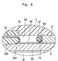
- FIG. 7 and 8 Illustrated in Figs. 7 and 8 is a fourth embodiment according to the present invention.
- This fourth embodiment has a feature in that, in place of the limiter ring 17 which is provided in the annular groove 12H in the first embodiment, the rear end of the rotary atomizing head is formed in an arcuate shape in section and a second arcuately curved portion is formed directly thereon.
- those component parts which are common with the foregoing first embodiment are designated by common reference numerals or characters to avoid repetitions of same explanations.
- a rotary atomizing head which is rotatably mounted on a fore end portion of the rotational shaft 9.
- this atomizing head 51 is constituted by an atomizing head body 52 and a hub member 53.
- the atomizing head body 52 of this embodiment is formed of an insulating synthetic resin material, and constituted by a bell cup 52A, a mounting portion 52A, an annular partition wall 52C, a paint spreading surface 52D, paint releasing edges 62E, a female screw portion 52F, and a hub mounting portion 52G.
- the atomizing head body 52 differs from the atomizing head body 12 of the first embodiment in that an arcuate end portion 52H of an arcuate shape in section is provided at the rear end of the mounting portion 52B to serve as a second arcuately curved portion.
- an arcuate coat film 55 is applied on circumferential surfaces of the arcuate end portion 52H as will be described hereinafter.
- the hub member 53 is constituted by a circular disk portion 53A and a cylindrical body portion 53B, and bored with a large number of first and second hub holes 53C and 53D.
- Denoted at 54 is an on-head semi-conductive coat film which is applied in a film-like shape on outer peripheral surfaces of the rotary atomizing head 51.
- the on-head semi-conductive coat film 54 of this embodiment is formed on circumferential surfaces between the rear end of the mounting portion 52B and the paint releasing edges 52E of the atomizing head body 52.
- Indicated at 55 is a second arcuate coat film which is formed on circumferential surfaces of the arcuate end portion 52H.
- the arcuate coat film 55 is formed by a semi-conductive film, and located between and electrically connected with the on-head semi-conductive coat film 54 and a power supply semi-conductive coat film 56 which will be described hereinafter.
- the arcuate end portion 52H is spaced from the limiter ring 15 by a gap space in the range of 10mm to 80mm, for example, by a gap space of 50mm, and formed to have a radius of curvature in the range of 0.5mm to 25mm.
- Indicated at 56 is a power supply semi-conductive coat film which is applied on outer peripheral surfaces of the rotational shaft 9.
- This power supply semi-conductive coat film 56 is in contact with the arcuate coat film 55 at its fore end, and has its rear end located in the vicinity of the fore end of the motor body 6. More specifically, the rear end of the power supply semi-conductive coat film 56 is located in such small gap relation with the fore end face 6D of the motor body 6 as to permit air discharge across an intervening gap space.
- the present embodiment can produce substantially the same operational effects as the foregoing first embodiment.
- having the second arcuate end portion 52H formed on the rotary atomizing head 51 it becomes possible to form the second arcuately curved portion during a fabrication process of the rotary atomizing head 51 and thus to reduce the number of steps of the fabrication process and to realize a cut in production cost.
- a first arcuately curved portion is formed by the first limiter ring 15 or 31 which is provided on the fore end of the motor body 6.
- the fore end of the air motor may be directly formed into an arcuate shape if desired.
- the power supply semi-conductive coat film 27 is formed on inner surfaces of the motor support case 23. If desired, it is possible to extend part of the shaping air ring as far as a position where the rotary atomizing head confronts face to face with the air motor and to provide the power supply semi-conductive coat film on the inner periphery of the shaping air ring.
- the coating machine employs a rotational shaft which is formed of an insulating material, so that it becomes possible to prevent occurrence of spark discharges between the rotational shaft and a coating object during coating operations even when the rotary atomizing head is moved to an abnormally close proximity to the coating object, guaranteeing safety and reliability in operation.
- a power supply semi-conductive coat film is provided either on inner peripheral surfaces of the cover or on outer peripheral surfaces of the rotational shaft, operatively in association with a first arcuately curved portion which is provided between a fore end portion of the air motor and the power supply semi-conductive coat film and a second arcuately curved portion which is provided between the power supply semi-conductive coat film and an on-head semi-conductive coat film formed on the rotary atomizing head. Therefore, it becomes possible to prevent occurrence of spark discharges between the fore end of the air motor and rear end of the rotary atomizing head even in case the rotary atomizing head is abruptly brought to the proximity to a coating object, thereby permitting to maintain high paint deposition efficiency along with enhanced operational safety.
- the rotational shaft is formed of insulating ceramic material, thereby preventing electrical discharges from the rotational shaft to a coating object during coating operations and at the same time permitting to enhance the strength and prevent deformations of the rotational shaft which is put in high speed rotation.
Landscapes
- Electrostatic Spraying Apparatus (AREA)
- Application Of Or Painting With Fluid Materials (AREA)
Applications Claiming Priority (3)
| Application Number | Priority Date | Filing Date | Title |
|---|---|---|---|
| JP10306330A JP2000117155A (ja) | 1998-10-13 | 1998-10-13 | 回転霧化頭型塗装装置 |
| JP30633098 | 1998-10-13 | ||
| PCT/JP1999/005573 WO2000021681A1 (en) | 1998-10-13 | 1999-10-08 | Rotary atomizing head type coating device |
Publications (1)
| Publication Number | Publication Date |
|---|---|
| EP1038588A1 true EP1038588A1 (de) | 2000-09-27 |
Family
ID=17955819
Family Applications (1)
| Application Number | Title | Priority Date | Filing Date |
|---|---|---|---|
| EP99970340A Withdrawn EP1038588A1 (de) | 1998-10-13 | 1999-10-08 | Beschichtungsvorrichtung mit einem rotierenden sprühkopf |
Country Status (5)
| Country | Link |
|---|---|
| US (1) | US6230994B1 (de) |
| EP (1) | EP1038588A1 (de) |
| JP (1) | JP2000117155A (de) |
| KR (1) | KR100351782B1 (de) |
| WO (1) | WO2000021681A1 (de) |
Cited By (4)
| Publication number | Priority date | Publication date | Assignee | Title |
|---|---|---|---|---|
| WO2005110005A1 (en) * | 2004-05-18 | 2005-11-24 | Lind Finance & Development Ab | Painting bell |
| FR2887475A1 (fr) * | 2005-06-23 | 2006-12-29 | Sames Technologies Soc Par Act | Projecteur rotatif de produit de revetement liquide et installation de produit de projection incorporant un tel projecteur |
| FR3004661A1 (fr) * | 2013-04-22 | 2014-10-24 | Sames Technologies | Projecteur electrostatique de produit de revetement liquide et installation de projection comprenant un tel projecteur |
| WO2016116261A1 (de) * | 2015-01-21 | 2016-07-28 | Dürr Systems GmbH | Glockenteller oder lenkluftring mit isolierender beschichtung |
Families Citing this family (19)
| Publication number | Priority date | Publication date | Assignee | Title |
|---|---|---|---|---|
| DE60141457D1 (de) * | 2000-12-20 | 2010-04-15 | Abb Kk | Beschichtungsvorrichtung mit einem rotationszerstäuberkopf |
| US9346064B2 (en) * | 2005-09-16 | 2016-05-24 | Carlisle Fluid Technologies, Inc. | Radius edge bell cup and method for shaping an atomized spray pattern |
| WO2007083677A1 (ja) * | 2006-01-19 | 2007-07-26 | Abb K.K. | 回転霧化頭型塗装装置 |
| JP4347372B2 (ja) * | 2007-08-10 | 2009-10-21 | トヨタ自動車株式会社 | 静電塗装装置 |
| US20090206182A1 (en) * | 2008-01-25 | 2009-08-20 | Abb Inc. | Rotary Atomizer with an Improved Valve |
| US20100145516A1 (en) * | 2008-12-08 | 2010-06-10 | Illinois Tool Works Inc. | High voltage monitoring system and method for spray coating systems |
| JP5504100B2 (ja) * | 2010-08-25 | 2014-05-28 | ランズバーグ・インダストリー株式会社 | 静電塗装機用の回転霧化頭 |
| JP5602561B2 (ja) | 2010-09-27 | 2014-10-08 | トヨタ自動車株式会社 | 静電塗装用塗装ガン |
| EP2859955B1 (de) * | 2012-06-06 | 2017-03-22 | Abb K.K. | Vorrichtung zum elektrostatischen lackieren |
| WO2013183417A1 (ja) * | 2012-06-06 | 2013-12-12 | Abb株式会社 | 静電塗装装置 |
| JP6044774B2 (ja) * | 2013-02-07 | 2016-12-14 | 株式会社大気社 | 静電塗装機 |
| DE102013212039A1 (de) * | 2013-06-25 | 2015-01-08 | Volkswagen Aktiengesellschaft | Applikationsvorrichtung |
| US8851397B1 (en) * | 2013-11-14 | 2014-10-07 | Efc Systems, Inc. | Bell cup atomizer having improved cleaning capability |
| DE102015004066A1 (de) * | 2015-03-28 | 2016-09-29 | Eisenmann Se | Wellenelement eines Luftlagers, Luftlager und Rotationszerstäuber |
| JP6444820B2 (ja) | 2015-07-01 | 2018-12-26 | ランズバーグ・インダストリー株式会社 | 静電塗装装置及び静電塗装機 |
| KR101634298B1 (ko) * | 2016-01-20 | 2016-06-30 | 박상은 | 더블 벨컵 |
| DE102018129964B4 (de) | 2018-11-27 | 2023-11-16 | Dürr Systems Ag | Rotationszerstäuber und dessen Betriebsverfahren sowie Beschichtungsroboter mit Rotationszerstäuber |
| EP4093554A4 (de) * | 2020-01-24 | 2024-01-17 | Carlisle Fluid Technologies, LLC | Elektrostatischer zerstäuber |
| JP7498763B2 (ja) * | 2021-12-22 | 2024-06-12 | シーエフティー エルエルシー | 静電塗装機及びこれに組み込まれる回転霧化頭並びにその製造方法 |
Family Cites Families (8)
| Publication number | Priority date | Publication date | Assignee | Title |
|---|---|---|---|---|
| US4576827A (en) * | 1984-04-23 | 1986-03-18 | Nordson Corporation | Electrostatic spray coating system |
| US4887770A (en) | 1986-04-18 | 1989-12-19 | Nordson Corporation | Electrostatic rotary atomizing liquid spray coating apparatus |
| US5433387A (en) | 1992-12-03 | 1995-07-18 | Ransburg Corporation | Nonincendive rotary atomizer |
| US5633306A (en) * | 1992-12-03 | 1997-05-27 | Ransburg Corporation | Nonincendive rotary atomizer |
| JP3266438B2 (ja) | 1994-09-30 | 2002-03-18 | エービービー株式会社 | 回転霧化頭型塗装装置 |
| JP3274613B2 (ja) * | 1996-12-06 | 2002-04-15 | エービービー株式会社 | 回転霧化頭型塗装装置 |
| US5853126A (en) * | 1997-02-05 | 1998-12-29 | Illinois Tool Works, Inc. | Quick disconnect for powder coating apparatus |
| US6076751A (en) * | 1998-12-15 | 2000-06-20 | Illinois Tool Works Inc. | Method of charging using nonincendive rotary atomizer |
-
1998
- 1998-10-13 JP JP10306330A patent/JP2000117155A/ja active Pending
-
1999
- 1999-10-08 KR KR1020007006417A patent/KR100351782B1/ko not_active Expired - Fee Related
- 1999-10-08 US US09/581,168 patent/US6230994B1/en not_active Expired - Fee Related
- 1999-10-08 EP EP99970340A patent/EP1038588A1/de not_active Withdrawn
- 1999-10-08 WO PCT/JP1999/005573 patent/WO2000021681A1/ja not_active Ceased
Non-Patent Citations (1)
| Title |
|---|
| See references of WO0021681A1 * |
Cited By (7)
| Publication number | Priority date | Publication date | Assignee | Title |
|---|---|---|---|---|
| WO2005110005A1 (en) * | 2004-05-18 | 2005-11-24 | Lind Finance & Development Ab | Painting bell |
| FR2887475A1 (fr) * | 2005-06-23 | 2006-12-29 | Sames Technologies Soc Par Act | Projecteur rotatif de produit de revetement liquide et installation de produit de projection incorporant un tel projecteur |
| FR3004661A1 (fr) * | 2013-04-22 | 2014-10-24 | Sames Technologies | Projecteur electrostatique de produit de revetement liquide et installation de projection comprenant un tel projecteur |
| WO2014173837A1 (fr) * | 2013-04-22 | 2014-10-30 | Sames Technologies | Projecteur electrostatique de produit de revetement liquide et installation de projection comprenant un tel projecteur |
| US9901941B2 (en) | 2013-04-22 | 2018-02-27 | Sames Kremlin | Electrostatic spray device for spraying a liquid coating product, and spray facility comprising such a spray device |
| WO2016116261A1 (de) * | 2015-01-21 | 2016-07-28 | Dürr Systems GmbH | Glockenteller oder lenkluftring mit isolierender beschichtung |
| US10773265B2 (en) | 2015-01-21 | 2020-09-15 | Dürr Systems Ag | Bell cup or atomizer ring comprising an insulating coating |
Also Published As
| Publication number | Publication date |
|---|---|
| KR100351782B1 (ko) | 2002-09-05 |
| JP2000117155A (ja) | 2000-04-25 |
| WO2000021681A1 (en) | 2000-04-20 |
| US6230994B1 (en) | 2001-05-15 |
| KR20010033058A (ko) | 2001-04-25 |
Similar Documents
| Publication | Publication Date | Title |
|---|---|---|
| US6230994B1 (en) | Rotary atomizing head type coating device | |
| US5775598A (en) | Rotary atomizing head type coating machine | |
| US8978580B2 (en) | Electrostatic coating apparatus | |
| US7546962B2 (en) | Electrostatic coating apparatus | |
| US4852810A (en) | Apparatus for electrostatic coating of objects | |
| US5358182A (en) | Device with rotating atomizer head for electrostatically spraying liquid coating product | |
| JPH0661491B2 (ja) | 被加工品の静電塗装装置 | |
| JPH04215864A (ja) | 静電塗装装置 | |
| CN105142796B (zh) | 用于喷涂液体涂料产品的静电喷涂装置及包括该喷涂装置的喷涂设备 | |
| JP3274613B2 (ja) | 回転霧化頭型塗装装置 | |
| JPH08187453A (ja) | 回転霧化頭型塗装装置 | |
| JP3266438B2 (ja) | 回転霧化頭型塗装装置 | |
| GB2142844A (en) | Sprayers | |
| JPH10235231A (ja) | 静電噴霧ガン | |
| JP2001252596A (ja) | 静電塗装装置 | |
| JP3379623B2 (ja) | 回転霧化頭型静電塗装装置 |
Legal Events
| Date | Code | Title | Description |
|---|---|---|---|
| PUAI | Public reference made under article 153(3) epc to a published international application that has entered the european phase |
Free format text: ORIGINAL CODE: 0009012 |
|
| 17P | Request for examination filed |
Effective date: 20000621 |
|
| AK | Designated contracting states |
Kind code of ref document: A1 Designated state(s): AT BE CH CY DE DK ES FI FR GB GR IE IT LI LU MC NL PT SE |
|
| RAP1 | Party data changed (applicant data changed or rights of an application transferred) |
Owner name: ABB K.K. |
|
| RBV | Designated contracting states (corrected) |
Designated state(s): DE FR GB |
|
| STAA | Information on the status of an ep patent application or granted ep patent |
Free format text: STATUS: THE APPLICATION IS DEEMED TO BE WITHDRAWN |
|
| 18D | Application deemed to be withdrawn |
Effective date: 20050501 |