EP1038621A2 - Assemblage de dent de coupe - Google Patents
Assemblage de dent de coupe Download PDFInfo
- Publication number
- EP1038621A2 EP1038621A2 EP99123958A EP99123958A EP1038621A2 EP 1038621 A2 EP1038621 A2 EP 1038621A2 EP 99123958 A EP99123958 A EP 99123958A EP 99123958 A EP99123958 A EP 99123958A EP 1038621 A2 EP1038621 A2 EP 1038621A2
- Authority
- EP
- European Patent Office
- Prior art keywords
- cutter tooth
- wheel
- assembly
- cutter
- Prior art date
- Legal status (The legal status is an assumption and is not a legal conclusion. Google has not performed a legal analysis and makes no representation as to the accuracy of the status listed.)
- Granted
Links
Images



Classifications
-
- A—HUMAN NECESSITIES
- A01—AGRICULTURE; FORESTRY; ANIMAL HUSBANDRY; HUNTING; TRAPPING; FISHING
- A01G—HORTICULTURE; CULTIVATION OF VEGETABLES, FLOWERS, RICE, FRUIT, VINES, HOPS OR SEAWEED; FORESTRY; WATERING
- A01G23/00—Forestry
- A01G23/02—Transplanting, uprooting, felling or delimbing trees
- A01G23/06—Uprooting or pulling up trees; Extracting or eliminating stumps
- A01G23/067—Uprooting or pulling up trees; Extracting or eliminating stumps by comminuting the tree stumps
-
- Y—GENERAL TAGGING OF NEW TECHNOLOGICAL DEVELOPMENTS; GENERAL TAGGING OF CROSS-SECTIONAL TECHNOLOGIES SPANNING OVER SEVERAL SECTIONS OF THE IPC; TECHNICAL SUBJECTS COVERED BY FORMER USPC CROSS-REFERENCE ART COLLECTIONS [XRACs] AND DIGESTS
- Y10—TECHNICAL SUBJECTS COVERED BY FORMER USPC
- Y10T—TECHNICAL SUBJECTS COVERED BY FORMER US CLASSIFICATION
- Y10T407/00—Cutters, for shaping
- Y10T407/19—Rotary cutting tool
- Y10T407/1906—Rotary cutting tool including holder [i.e., head] having seat for inserted tool
- Y10T407/1928—Tool adjustable relative to holder
-
- Y—GENERAL TAGGING OF NEW TECHNOLOGICAL DEVELOPMENTS; GENERAL TAGGING OF CROSS-SECTIONAL TECHNOLOGIES SPANNING OVER SEVERAL SECTIONS OF THE IPC; TECHNICAL SUBJECTS COVERED BY FORMER USPC CROSS-REFERENCE ART COLLECTIONS [XRACs] AND DIGESTS
- Y10—TECHNICAL SUBJECTS COVERED BY FORMER USPC
- Y10T—TECHNICAL SUBJECTS COVERED BY FORMER US CLASSIFICATION
- Y10T407/00—Cutters, for shaping
- Y10T407/22—Cutters, for shaping including holder having seat for inserted tool
- Y10T407/2222—Tool adjustable relative to holder
- Y10T407/2226—Plural provisions for adjustment
- Y10T407/223—Plural provisions for adjustment including pivotable seat or tool
-
- Y—GENERAL TAGGING OF NEW TECHNOLOGICAL DEVELOPMENTS; GENERAL TAGGING OF CROSS-SECTIONAL TECHNOLOGIES SPANNING OVER SEVERAL SECTIONS OF THE IPC; TECHNICAL SUBJECTS COVERED BY FORMER USPC CROSS-REFERENCE ART COLLECTIONS [XRACs] AND DIGESTS
- Y10—TECHNICAL SUBJECTS COVERED BY FORMER USPC
- Y10T—TECHNICAL SUBJECTS COVERED BY FORMER US CLASSIFICATION
- Y10T83/00—Cutting
- Y10T83/929—Tool or tool with support
- Y10T83/9319—Toothed blade or tooth therefor
- Y10T83/9326—Plural separable sections
- Y10T83/9329—Tooth separable from blade
- Y10T83/9331—By independent connecting element
- Y10T83/9333—Transversely movable
-
- Y—GENERAL TAGGING OF NEW TECHNOLOGICAL DEVELOPMENTS; GENERAL TAGGING OF CROSS-SECTIONAL TECHNOLOGIES SPANNING OVER SEVERAL SECTIONS OF THE IPC; TECHNICAL SUBJECTS COVERED BY FORMER USPC CROSS-REFERENCE ART COLLECTIONS [XRACs] AND DIGESTS
- Y10—TECHNICAL SUBJECTS COVERED BY FORMER USPC
- Y10T—TECHNICAL SUBJECTS COVERED BY FORMER US CLASSIFICATION
- Y10T83/00—Cutting
- Y10T83/929—Tool or tool with support
- Y10T83/9319—Toothed blade or tooth therefor
- Y10T83/9367—Teeth having cutting edge perpendicular to blade surface
Definitions
- stump grinding machines there are a number of machines that use teeth to impinge or disintegrate a piece of material and/or the earth strata. Examples of these machines include land clearing machines, tub grinders, force feed grinders, and stump grinding machines. As can be appreciated, these machines are used to cut or disintegrate wood and brush. Referring to the latter of the above-mentioned machines, i.e., stump grinding machines, these machines typically include a plurality of stump cutter teeth mounted to the circumference of a driven wheel. In a typical stump grinding operation, the stump grinding machine is positioned adjacent to the stump. The wheel then is rotated so as to drive the cutter teeth into the stump. After a plurality cuts (or passes) the end result is the disintegration of the stump to a predetermined depth below the surface of the ground.
- stump grinding machines typically include a plurality of stump cutter teeth mounted to the circumference of a driven wheel. In a typical stump grinding operation, the stump grinding machine is positioned adjacent to the stump. The wheel then is rotated so as to drive the cutter teeth
- stump grinding places a tremendous amount of stress upon the stump cutter teeth, as well as upon the structure which supports each stump cutter tooth.
- the cutter teeth themselves must be strong and rugged so as to be able to withstand the stresses associated with the stump cutting operation.
- the holder assembly must also be also to withstand these same stresses and still hold the stump cutter tooth therein.
- the invention is a cutter tooth assembly for impinging a material.
- the cutter tooth assembly attaches to a driven member which has a side surface and a circumferential surface.
- the assembly comprises a cutter tooth which has an elongate body with a leading end and a trailing end.
- a hard insert is at the leading end of the tooth.
- the cutter assembly further includes a pocket includes a base portion and a holder portion wherein the pocket attaches to the side surface of the driven member at the base portion thereof.
- the cutter tooth is retained to the pocket at the holder portion thereof.
- the base portion of the pocket has a leading surface and a trailing surface.
- the cutter tooth is retained by the holder portion of the pocket so that the hard insert extends circumferentially past the leading surface of the base portion of the pocket.
- the invention is a cutter tooth assembly for attachment to a rotatable wheel which has a side surface and a circumferential surface.
- the assembly comprises a cutter tooth which has a hard insert.
- the assembly also has a pocket which is attachable to the side surface of the wheel. The pocket retains the cutter tooth.
- the cutter tooth is indexable to one of a plurality of positions relative to the pocket.
- the invention is a pocket for holding a cutter tooth and being attachable to a driven member.
- the pocket comprises a base portion and a holder portion.
- the pocket is attachable to the driven member at the base portion thereof.
- the holder portion retains the cutter tooth.
- the base portion presents at least one external contact surface.
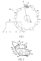
- FIG.1 illustrates a stump grinder (or cutter) assembly which is generally designated as 20.
- Stump grinder assembly 20 includes a plurality of stump cutter tooth assemblies wherein each stump cutter tooth assembly is generally designated as 22.
- the stump grinder assembly further includes a wheel 24.
- the wheel 24 presents a pair of side surfaces wherein only one side surface 26 is illustrated and a circumferential edge 28.
- the wheel 24 contains a plurality of series (or pairs) of threaded holes 30 (see FIG. 2) which are spaced about the circumference 28 thereof.
- the cutter tooth assembly 22 is attached to the wheel 24 via these holes 30.
- FIG. 1 further illustrates the stump cutter teeth engaging the stump (or substrate) 32 so as to disintegrate the stump 32.
- the stump 32 is disintegrated to a predetermined depth below the surface of the ground.
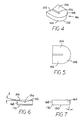
- the cutter tooth assembly 22 comprises a pocket 36 and a cutter tooth 38.
- Bolts 40 fasten the pocket 36 to the one surface 26 of the wheel 24 as will be described hereinafter.
- pocket 36 includes a base portion 44 which has an interior surface 46 and an exterior surface 48.
- the base portion 44 further includes a leading end 50 and a trailing end 52.
- the leading end 50 of the base portion 44 presents upper leading bevelled (or chamfered) surfaces 54 and lower leading bevelled (or chamfered) surfaces 56.
- a pair of holes 57 are in the pocket base 44.
- Each hole 57 has an exterior portion 58 and an interior portion 59 wherein a shoulder 60 separates the exterior and interior portions (58, 59) of the hole 57.
- the exterior portion 57 has a larger diameter than the diameter of the interior portion 58.
- the upper leading bevelled surfaces 54 are on opposite sides of a central flat surface 62.
- the lower leading bevelled surfaces 56 are also on opposite sides of the central flat surface 62.
- the pocket 36 base portion 44 further presents an upper contact surface 64.
- Pocket 36 further includes an integral holder portion 66.
- Holder portion 66 contains a bore 68.
- Holder portion 66 has a leading face 70 and a trailing face 72.
- Bore 68 includes a leading bore portion 73 and a trailing bore portion 74.
- the leading bore portion 73 is of a diameter that is larger then the diameter of the trailing bore portion 74.
- a bore shoulder 75 joins the leading and trailing bore portions (73, 74).
- a frusto-conical surface (or mouth) 76 surrounds the bore 68 at the leading face 70 of the holder portion 66.
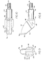
- cutter tooth 38 includes an elongate body 88 that presents a leading end 90 and a trailing end 91.
- a head portion 92 is at the leading and 90 of the body 88.
- a shank portion 93 is at the trailing end 91 of the body 88.
- the head portion 92 contains a recess 94 that receives a hard insert 96.
- the hard insert 96 is illustrated as presenting a generally flat leading surface 150.
- the rear surface of the hard insert 96 has a lower portion comprising a pair of opposite bevelled surfaces 152, 154. These bevelled surfaces (152, 154) are disposed at an angle "A" with respect to the flat leading surface 150.
- the preferred angle "A" is about ten degrees.
- a radiused surface 156 joins the bevelled surfaces 152, 154.
- the rear surface of the hard insert 96 also has an upper portion 158.
- the hard insert 96 presents a generally arcuate cutting edge 162 which at the intersection of the leading surface 150 and the arcuate top edge 164.
- the top edge 164 is relieved at an angle "B" which preferably is about ten degrees.
- the bottom edge 168 of the hard insert 96 includes a chamfer 170.
- the recess 94 presents a surface with corresponds to the rear surface of the hard insert so that the hard insert securely attaches to the recess by brazing or the like.
- the head portion 92 presents upper bevelled surfaces 102 which are on opposite sides of an upper central strip 104.
- the head portion 92 also presents lower bevelled surfaces 106 which are on opposite sides of a lower central strip 108.
- the shank portion 93 includes a smooth portion 110 and a threaded portion 112 wherein a shank shoulder 114 separates the smooth and threaded portions (110 and 112).
- a frusto-conical shoulder 116 separates the head portion 92 and the shank portion 93.
- the stump cutter tooth 38 includes a neutral contact surface 120, a lower interior contact surface 122, a lower exterior contact surface 124, an upper interior contact surface 126, and an upper exterior contact surface 128.
- the lower interior contact surface 122 and the lower exterior contact surface 124 are each disposed at an angle of about 45 degrees with respect to the surface of the neutral contact surface 120.
- the upper interior contact surface 126 and the upper exterior contact surface 128 are each disposed at an angle of about 90 degrees with respect to the surface of the neutral contact surface 120.
- the holes 57 of the pocket 36 are aligned with the corresponding holes 30 in the wheel 24.
- the bolt 40 are passed through their corresponding holes 57 in the pocket 36.
- Each bolt 40 engages the threads in the hole 30 so that upon rotation the bolt 40 moves so as to abut the shoulder 60 and then draw the pocket 36 into tight contact against the one surface 26 of the wheel 24.
- the shank portion 93 of the cutter tooth 38 is positioned in the bore 68 of the holder portion 66 to a point where the shoulder 114 of the shank 93 contacts the shoulder 75 of the holder bore 66.
- the threaded shank portion 112 (or at least a part of the threaded shank portion 112) extends past the trailing face 72 of the holder 66.
- a nut 132 is threaded onto the threaded shank portion 112. The nut 132 is rotated until the cutter tooth 38 is very securely and tightly attached to the holder portion 66 of the pocket 36.
- the nut 132 is removed from the threaded shank portion 112 and the cutter tooth removed from the bore 68 of the holder portion 66.
- the wheel of the stump grinding assembly is rotated so as to drive the stump cutter teeth into the stump so as to disintegrate the stump.
- the stump cutter tooth assembly of the instant invention provides a number of advantages which improve the overall operational efficiency of the stump cutter tooth assembly.
- FIG. 14 illustrates an embodiment of a stump cutter wheel 200 wherein there are shown five stump cutter tooth assemblies (204, 206, 208, 210, 212) wherein each stump cutter tooth assembly is positioned at a different position relative to the peripheral edge of the stump cutter wheel.
- each stump cutter tooth assembly the cutter tooth 38 is indexed to a selected one of a plurality of discrete positions relative to the pocket 36 as will be described hereinafter.
- stump cutter tooth assembly 204 has the upper contact surface of the pocket thereof even with the peripheral edge of the wheel.
- the cutter tooth is disposed 90 degrees toward the wheel.
- Stump cutter tooth assembly 206 has the upper contact surface of the pocket thereof disposed a distance "C” below the peripheral edge of the wheel.
- the cutter tooth is disposed 45 degrees toward the wheel.
- Stump cutter tooth assembly 208 has the upper contact surface of the pocket thereof disposed a distance "D" below the peripheral edge of the wheel.
- the cutter tooth is disposed parallel to, i.e., neutral with, the surface of the wheel.
- Stump cutter tooth assembly 210 has the upper contact surface of the pocket thereof disposed a distance "E” below the peripheral edge of the wheel.
- the cutter tooth is disposed 45 degrees away from the wheel.
- Stump cutter tooth assembly 212 has the upper contact surface of the pocket thereof disposed a distance "F below the peripheral edge of the wheel.
- the cutter tooth is disposed 90 degrees away from the wheel.
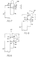
- FIG. 15 illustrates the stump cutter tooth assembly 204.
- the stump cutter tooth 38 is in a position wherein the upper interior contact surface 126 is in contact with the upper contact surface 64 of the pocket 36. In this position, the central axis of the cutter tooth 38 is disposed at angle of "z" about 90 degrees with respect to the surface of the wheel (or the vertical as shown in the drawing).
- the contact between the upper interior contact surface 126 of the cutter tooth 38 and the upper contact surface 64 of the pocket 36 facilitates the stability and strength of the attachment of the cutter tooth to the pocket during the cutting operation. In this position one may consider the cutter tooth to be disposed toward the wheel at an included angle (i.e., "z") of about 90 degrees.
- FIG. 16 illustrates the stump cutter tooth assembly 206.
- the cutter tooth 38 is in a position wherein the lower interior contact surface 122 is in contact with the upper contact surface 64 of the pocket 36. In this position, the transverse axis of the cutter tooth 38 is disposed at angle of "y" about 45 degrees with respect to the surface of the wheel (or the vertical as shown in the drawing).
- the contact between the lower interior contact surface 122 of the cutter tooth 38 and the upper contact surface 64 of the pocket 36, as well as the contact between the upper interior contact surface 126 and the wheel facilitates the stability and strength of the attachment of the cutter tooth to the pocket during the cutting operation. In this position one may consider the cutter tooth to be disposed toward the wheel at an included angle (i.e., "y") of about 45 degrees. Further, the upper contact surface of the pocket is disposed a distance "C" below the peripheral edge of the wheel.
- FIG. 17 illustrates the stump cutter tooth assembly 208.
- the stump cutter tooth 38 in a position wherein the bottom contact surface 120 contacts against the upper contact surface 64 of the pocket 36.
- the upper contact surface of the pocket is disposed a distance "D" below the peripheral edge of the wheel.
- FIG. 18 illustrates the stump cutter tooth assembly 210.
- the stump cutter tooth 38 in a position wherein the lower exterior contact surface 124 is in contact with the upper contact surface 64 of the pocket 36. In this position, the transverse axis of the cutter tooth 38 is disposed at angle of "w" about 45 degrees with respect to the surface of the wheel (or the vertical as shown in the drawing).
- the contact between the lower exterior contact surface 124 of the cutter tooth 38 and the upper contact surface 64 of the pocket 36, as well as the contact between the lower interior contact surface 122 and the wheel facilitates the stability and strength of the attachment of the cutter tooth to the pocket during the cutting operation. In this position one may consider the cutter tooth to be disposed away from the wheel at an included angle (i.e., "w") of about 45 degrees.
- the upper contact surface of the pocket is positioned a distance "E" below the peripheral edge of the wheel.
- FIG. 19 illustrates the stump cutter tooth 38 in a position wherein the upper exterior contact surface 128 is in contact with the upper contact surface 64 of the pocket 36.
- the transverse axis of the cutter tooth 38 is disposed at angle of "x" about 90 degrees with respect to the surface of the wheel (or the vertical as shown in the drawing).
- the contact between the upper exterior contact surface 128 of the cutter tooth 38 and the upper contact surface 64 of the pocket 36, as well as the contact between the bottom contact surface 120 and the wheel facilitates the stability and strength of the attachment of the cutter tooth to the pocket during the cutting operation.
- the cutter tooth In this position one may consider the cutter tooth to be disposed away from the wheel at an included angle (i.e., "x") of about 90 degrees.
- the upper contact surface of the pocket is disposed a distance "F" below the peripheral edge of the wheel. In regard to the magnitude of these distances, they follow the following relationship: C ⁇ D ⁇ E ⁇ F.
- the instant invention provides the advantage of being able to index the stump cutter tooth with respect to the pocket.
- the operator may be able to adjust the stump cutter assembly to accommodate a variety of specific cutting situations.
- the ability to index the cutter tooth over the wheel which are the positions illustrated in FIGS. 15 and 16, is especially useful for making a so-called plunge cut into the stump.
- the cutter tooth in a position wherein the hard insert is circumferentially past (or axially forward of) the remainder of the cutter bit assembly including the pocket.
- This position may be considered to be a cab-forward position of the cutter tooth with respect to the pocket.
- the cutter tooth When in this so-called cab-forward orientation, the cutter tooth first engages the stump thereby keeping the pocket out of the stump so as to increase the overall efficiency of the stump cutting operation.
- This cab-forward design also provides for the increased clearance between the cutter tooth and the pocket and the wheel, and hence, provides for better passage of the wood chips away from the cutter tooth assembly.
- the stump cutter tooth assembly is attached to the wheel in such a fashion so that the central axis of the cutter tooth is generally tangential to circumferential edge of the wheel.
- the stump cutter tooth has an orientation so that the cutting forces are generally parallel to the central longitudinal axis of the shank of the cutter tooth.
- each stump cutter tooth assembly has an orientation such that the leading face of the hard insert lies along a line (R-R) coaxial with the radius of the wheel (see FIG. 1).
- the stump cutter tooth has a bevelled (or chamfered) leading face which provides for the deflection of debris from the stump cutting operation. By providing this deflection, there is an improvement in the overall efficiency of the cutting operation.
- the cutter tooth may also present a hard insert that has a bevelled (or chamfered) rearward face which provides for maximum cutting potential when the cutter tooth is indexed either toward or away from the wheel.
- a hard insert that has a bevelled (or chamfered) rearward face which provides for maximum cutting potential when the cutter tooth is indexed either toward or away from the wheel.
- Such a design permits the use of one hard (carbide) insert for both cuts wherein the stump cutter tooth is positioned away from the wheel or toward the wheel or neutral with respect to the wheel.
- the hard insert is suitable to perform all three (i.e., away from the wheel, toward the wheel, and neutral with respect to the wheel) types of cuts.
- the pocket has a leading face which has a bevelled (or chamfered) face which also provides for the deflection of debris from the cutting operation. By providing this debris deflection, there is an improvement in the overall efficiency of the cutting operation.
- Another advantage with the instant invention is a pocket which provides for an increase in the bearing area between the pocket and the wheel. Such a bearing area results in a decrease in the deformation of the wheel during the stump grinding operation.
- Still another advantage of the instant invention is the ability to provide for the quick and easy replacement of the cutter tooth due to the use of a nut threaded onto the threaded portion of the shank to attach the cutter tooth to the pocket.
Landscapes
- Life Sciences & Earth Sciences (AREA)
- Biodiversity & Conservation Biology (AREA)
- Ecology (AREA)
- Forests & Forestry (AREA)
- Environmental Sciences (AREA)
- Harvester Elements (AREA)
Applications Claiming Priority (2)
| Application Number | Priority Date | Filing Date | Title |
|---|---|---|---|
| US09/273,936 US6024143A (en) | 1999-03-22 | 1999-03-22 | Cutting tooth assembly |
| US273936 | 1999-03-22 |
Publications (3)
| Publication Number | Publication Date |
|---|---|
| EP1038621A2 true EP1038621A2 (fr) | 2000-09-27 |
| EP1038621A3 EP1038621A3 (fr) | 2004-05-19 |
| EP1038621B1 EP1038621B1 (fr) | 2006-07-12 |
Family
ID=23046054
Family Applications (1)
| Application Number | Title | Priority Date | Filing Date |
|---|---|---|---|
| EP99123958A Expired - Lifetime EP1038621B1 (fr) | 1999-03-22 | 1999-12-06 | Assemblage de dent de coupe |
Country Status (3)
| Country | Link |
|---|---|
| US (1) | US6024143A (fr) |
| EP (1) | EP1038621B1 (fr) |
| DE (1) | DE69932315T2 (fr) |
Cited By (1)
| Publication number | Priority date | Publication date | Assignee | Title |
|---|---|---|---|---|
| EP1457106A1 (fr) * | 2001-04-19 | 2004-09-15 | Sandvik AB | Dent pour broyeur des souches d'arbres et broyeur |
Families Citing this family (41)
| Publication number | Priority date | Publication date | Assignee | Title |
|---|---|---|---|---|
| US6365453B1 (en) * | 1999-06-16 | 2002-04-02 | Micron Technology, Inc. | Method and structure for reducing contact aspect ratios |
| US20040025658A1 (en) * | 1999-12-10 | 2004-02-12 | Fisher George F. | Polymer cutting apparatus and method |
| US7299836B2 (en) | 2000-07-19 | 2007-11-27 | Green Kevin J | Stump cutting tooth and pocket |
| US8201598B2 (en) * | 2000-07-19 | 2012-06-19 | Green Kevin J | Cutting tool for use with a stump cutting apparatus |
| US6484766B1 (en) | 2001-08-27 | 2002-11-26 | Bb&F Enterprises, Llc | Stump grinding apparatus having improved cutter tool |
| US7216682B1 (en) | 2001-12-31 | 2007-05-15 | Bennington John T | Split wheel stump cutter with replaceable tooth blocks and cutting teeth |
| US6698477B1 (en) | 2001-12-31 | 2004-03-02 | John T. Bennington | Split wheel stump cutter with replaceable tooth blocks and cutting teeth |
| US6848485B1 (en) * | 2004-01-21 | 2005-02-01 | Sandvik Mgt Llc | Stump grinding apparatus having a rotatable toothed disc |
| US20060102247A1 (en) * | 2004-11-16 | 2006-05-18 | Green Kevin J | Tool holder for supporting a cutting tool |
| PE20080597A1 (es) * | 2006-04-24 | 2008-05-17 | Esco Corp | Montaje de desgaste |
| US8408258B2 (en) * | 2006-10-27 | 2013-04-02 | Leonardi Manufacturing Co. | Shock absorbing system for stump grinding apparatus |
| US8020591B2 (en) * | 2006-11-02 | 2011-09-20 | Kennametal Inc. | Indexable stump cutter tooth |
| US7913727B2 (en) * | 2006-12-14 | 2011-03-29 | Green Kevin J | Stump cutting tool for use with a stump cutting apparatus |
| EA022167B1 (ru) * | 2008-01-08 | 2015-11-30 | Эско Корпорейшн | Наконечник рабочего валка машины для разработки грунта |
| US8540033B2 (en) * | 2008-02-22 | 2013-09-24 | Fecon, Inc. | Apparatus for land clearing and preparation |
| USD757124S1 (en) | 2009-02-23 | 2016-05-24 | Fecon, Inc. | Land clearing tool interface |
| EP2434861A4 (fr) * | 2009-05-28 | 2016-09-28 | Gilles Denis | Coupe-broussailles |
| US20140338790A1 (en) | 2012-05-04 | 2014-11-20 | Kevin J. Green | Stump Cutting Apparatus |
| US9578816B2 (en) | 2012-05-04 | 2017-02-28 | Green Manufacturing, Inc. | Stump cutting apparatus |
| US9686922B2 (en) | 2012-05-18 | 2017-06-27 | Keith Cairns | Stump grinder cutting system |
| USD675236S1 (en) * | 2012-05-18 | 2013-01-29 | Keith Cairns | Cutting element for stump grinder |
| USD699269S1 (en) | 2012-08-01 | 2014-02-11 | Beaver Mulching Inc. | Combined mulching tooth and holder |
| US9907237B2 (en) | 2013-03-15 | 2018-03-06 | Green Manufacturing, Inc. | Cutting assembly for a stump cutting apparatus |
| USD772951S1 (en) | 2014-02-24 | 2016-11-29 | Fecon, Inc. | Land clearing tool assembly with a depth control ring and a drum interface |
| USD798913S1 (en) | 2016-02-04 | 2017-10-03 | Beaver Mulching Inc. | Combined mulching tooth and depth limiter |
| USD835680S1 (en) | 2017-01-24 | 2018-12-11 | Fecon, Inc. | Land clearing tool interface |
| USD835682S1 (en) | 2017-01-24 | 2018-12-11 | Fecon, Inc. | Land clearing tool interface |
| USD836137S1 (en) | 2017-01-24 | 2018-12-18 | Fecon, Inc. | Land clearing tool interface |
| USD835681S1 (en) | 2017-01-24 | 2018-12-11 | Fecon, Inc. | Land clearing tool interface |
| US11065623B1 (en) | 2017-05-31 | 2021-07-20 | Stephen Rock | Grinding blade for an angle grinder |
| EP3749084A2 (fr) | 2018-02-07 | 2020-12-16 | Vermeer Manufacturing Company | Systèmes de montage d'outil de coupe et outils de coupe correspondant |
| USD854586S1 (en) | 2018-05-01 | 2019-07-23 | Fecon, Inc. | Land clearing tool |
| US10945385B2 (en) | 2018-07-12 | 2021-03-16 | Vermeer Manufacturing Company | Stump cutter tooth |
| US10856474B2 (en) | 2018-07-12 | 2020-12-08 | Kennametal Inc. | Stump cutter tooth assembly |
| USD965031S1 (en) | 2018-07-12 | 2022-09-27 | Kennametal Inc. | Stump cutter tooth |
| US10851523B2 (en) | 2018-11-05 | 2020-12-01 | Caterpillar Inc. | Retention system for motor grader bits |
| USD909436S1 (en) | 2019-01-17 | 2021-02-02 | Vermeer Manufacturing Company | Cutter |
| USD939599S1 (en) | 2019-02-07 | 2021-12-28 | Vermeer Manufacturing Company | Cutter |
| USD945505S1 (en) | 2019-08-07 | 2022-03-08 | Vermeer Manufacturing Company | Cutter |
| USD1055121S1 (en) | 2022-01-24 | 2024-12-24 | Vermeer Manufacturing Company | Cutter |
| USD1107081S1 (en) | 2024-09-12 | 2025-12-23 | Vermeer Manufacturing Company | Cutter |
Family Cites Families (15)
| Publication number | Priority date | Publication date | Assignee | Title |
|---|---|---|---|---|
| US2121044A (en) * | 1934-11-27 | 1938-06-21 | Sullivan Machinery Co | Cutter chain |
| US2078475A (en) * | 1934-12-07 | 1937-04-27 | Armstrong Bros Tool Co | Tool holder |
| NL81663C (fr) * | 1950-01-20 | |||
| US4335921A (en) * | 1977-06-06 | 1982-06-22 | Cmi Corporation | Cutting head for a paved roadway resurfacing apparatus |
| US4316636A (en) * | 1979-02-01 | 1982-02-23 | Kennametal Inc. | Excavation and road maintenance bits and blocks |
| US4744278A (en) * | 1985-04-22 | 1988-05-17 | Weyerhaeuser Company | Rotary machining tool and method of its manufacture |
| GB2194874B (en) * | 1986-02-24 | 1990-06-06 | James Wilson | Cutting tool |
| US4727664A (en) * | 1986-07-09 | 1988-03-01 | Hemphill Industries, Inc. | Digging tooth and holder therefor |
| US4750396A (en) * | 1986-12-01 | 1988-06-14 | Weyerhaeuser Company | Cutter tooth and tool employing it |
| US5007685A (en) * | 1989-01-17 | 1991-04-16 | Kennametal Inc. | Trenching tool assembly with dual indexing capability |
| US4998574A (en) * | 1989-12-01 | 1991-03-12 | Kennametal Inc. | Cutting bit and block mount |
| US5131305A (en) * | 1990-01-23 | 1992-07-21 | Maclennan Charles D | Saw tooth and holder |
| US5005622A (en) * | 1990-02-16 | 1991-04-09 | Kennametal Inc. | Block and locking mechanism for a stump grinding cutter bit and method of securing and retaining |
| US5261306A (en) * | 1992-02-28 | 1993-11-16 | Wood Technology, Inc. | Circular saw blade for tree cutting and bunching vehicles |
| US5743314A (en) * | 1996-04-22 | 1998-04-28 | Green Manufacturing Inc. | Stump cutting tool assembly |
-
1999
- 1999-03-22 US US09/273,936 patent/US6024143A/en not_active Expired - Lifetime
- 1999-12-06 EP EP99123958A patent/EP1038621B1/fr not_active Expired - Lifetime
- 1999-12-06 DE DE69932315T patent/DE69932315T2/de not_active Expired - Lifetime
Cited By (1)
| Publication number | Priority date | Publication date | Assignee | Title |
|---|---|---|---|---|
| EP1457106A1 (fr) * | 2001-04-19 | 2004-09-15 | Sandvik AB | Dent pour broyeur des souches d'arbres et broyeur |
Also Published As
| Publication number | Publication date |
|---|---|
| US6024143A (en) | 2000-02-15 |
| DE69932315D1 (de) | 2006-08-24 |
| DE69932315T2 (de) | 2007-07-05 |
| EP1038621B1 (fr) | 2006-07-12 |
| EP1038621A3 (fr) | 2004-05-19 |
Similar Documents
| Publication | Publication Date | Title |
|---|---|---|
| US6024143A (en) | Cutting tooth assembly | |
| US8522843B2 (en) | Indexable stump cutter tooth | |
| US6508612B1 (en) | Milling cutter capable of using inserts of various geometrical shapes | |
| EP1379122B1 (fr) | Roue de broyeuse de souche et dispositifs de coupe correspondants | |
| EP1330950B1 (fr) | Broyeur de souches | |
| US6769343B2 (en) | Tree felling disc saw tooth and blade construction | |
| US5007685A (en) | Trenching tool assembly with dual indexing capability | |
| US6523768B2 (en) | Rotary mill having releasable wedge-lock tool insert holding system | |
| AU2002253760A1 (en) | Stump grinding wheel and cutting assemblies therefor | |
| CA2124747C (fr) | Construction de dent de scie | |
| US20040216580A1 (en) | Circular saw blade assembly for a tree felling head | |
| US8201598B2 (en) | Cutting tool for use with a stump cutting apparatus | |
| US5143163A (en) | Digging tooth | |
| EP0480759A1 (fr) | Assemblage de couteaux pour déchiqueteur de souches | |
| US5067262A (en) | Digging tooth | |
| US6848485B1 (en) | Stump grinding apparatus having a rotatable toothed disc | |
| US6044919A (en) | Rotary spade drill arrangement | |
| US4461513A (en) | Rotary stone-cutting head | |
| JPH0698524B2 (ja) | スロ−アウエイチツプ | |
| JPH0453855Y2 (fr) | ||
| JPH09155622A (ja) | フライスカッタ | |
| US20060290198A1 (en) | Cutting tool | |
| GB2411564A (en) | Stump grinding apparatus having a rotatable toothed disc | |
| JPS63245312A (ja) | ドリル |
Legal Events
| Date | Code | Title | Description |
|---|---|---|---|
| PUAI | Public reference made under article 153(3) epc to a published international application that has entered the european phase |
Free format text: ORIGINAL CODE: 0009012 |
|
| AK | Designated contracting states |
Kind code of ref document: A2 Designated state(s): AT BE CH CY DE DK ES FI FR GB GR IE IT LI LU MC NL PT SE |
|
| AX | Request for extension of the european patent |
Free format text: AL;LT;LV;MK;RO;SI |
|
| PUAL | Search report despatched |
Free format text: ORIGINAL CODE: 0009013 |
|
| AK | Designated contracting states |
Kind code of ref document: A3 Designated state(s): AT BE CH CY DE DK ES FI FR GB GR IE IT LI LU MC NL PT SE |
|
| AX | Request for extension of the european patent |
Extension state: AL LT LV MK RO SI |
|
| RIC1 | Information provided on ipc code assigned before grant |
Ipc: 7A 01G 23/06 A |
|
| 17P | Request for examination filed |
Effective date: 20041119 |
|
| AKX | Designation fees paid |
Designated state(s): DE FR GB |
|
| 17Q | First examination report despatched |
Effective date: 20050425 |
|
| RBV | Designated contracting states (corrected) |
Designated state(s): DE FR GB |
|
| GRAP | Despatch of communication of intention to grant a patent |
Free format text: ORIGINAL CODE: EPIDOSNIGR1 |
|
| GRAS | Grant fee paid |
Free format text: ORIGINAL CODE: EPIDOSNIGR3 |
|
| GRAA | (expected) grant |
Free format text: ORIGINAL CODE: 0009210 |
|
| AK | Designated contracting states |
Kind code of ref document: B1 Designated state(s): DE FR GB |
|
| REG | Reference to a national code |
Ref country code: GB Ref legal event code: FG4D |
|
| REF | Corresponds to: |
Ref document number: 69932315 Country of ref document: DE Date of ref document: 20060824 Kind code of ref document: P |
|
| ET | Fr: translation filed | ||
| PLBE | No opposition filed within time limit |
Free format text: ORIGINAL CODE: 0009261 |
|
| STAA | Information on the status of an ep patent application or granted ep patent |
Free format text: STATUS: NO OPPOSITION FILED WITHIN TIME LIMIT |
|
| 26N | No opposition filed |
Effective date: 20070413 |
|
| PGFP | Annual fee paid to national office [announced via postgrant information from national office to epo] |
Ref country code: GB Payment date: 20091106 Year of fee payment: 11 Ref country code: FR Payment date: 20091215 Year of fee payment: 11 |
|
| PGFP | Annual fee paid to national office [announced via postgrant information from national office to epo] |
Ref country code: DE Payment date: 20101230 Year of fee payment: 12 |
|
| GBPC | Gb: european patent ceased through non-payment of renewal fee |
Effective date: 20101206 |
|
| REG | Reference to a national code |
Ref country code: FR Ref legal event code: ST Effective date: 20110831 |
|
| PG25 | Lapsed in a contracting state [announced via postgrant information from national office to epo] |
Ref country code: FR Free format text: LAPSE BECAUSE OF NON-PAYMENT OF DUE FEES Effective date: 20110103 |
|
| PG25 | Lapsed in a contracting state [announced via postgrant information from national office to epo] |
Ref country code: GB Free format text: LAPSE BECAUSE OF NON-PAYMENT OF DUE FEES Effective date: 20101206 |
|
| REG | Reference to a national code |
Ref country code: DE Ref legal event code: R119 Ref document number: 69932315 Country of ref document: DE Effective date: 20120703 |
|
| PG25 | Lapsed in a contracting state [announced via postgrant information from national office to epo] |
Ref country code: DE Free format text: LAPSE BECAUSE OF NON-PAYMENT OF DUE FEES Effective date: 20120703 |