EP1039312A2 - Système et méthode d'imagerie à ultrasons pour réaliser une image harmonique optimalisée - Google Patents
Système et méthode d'imagerie à ultrasons pour réaliser une image harmonique optimalisée Download PDFInfo
- Publication number
- EP1039312A2 EP1039312A2 EP99125028A EP99125028A EP1039312A2 EP 1039312 A2 EP1039312 A2 EP 1039312A2 EP 99125028 A EP99125028 A EP 99125028A EP 99125028 A EP99125028 A EP 99125028A EP 1039312 A2 EP1039312 A2 EP 1039312A2
- Authority
- EP
- European Patent Office
- Prior art keywords
- ultrasonic
- signal
- ohi
- harmonic image
- harmonic
- Prior art date
- Legal status (The legal status is an assumption and is not a legal conclusion. Google has not performed a legal analysis and makes no representation as to the accuracy of the status listed.)
- Withdrawn
Links
Images


Classifications
-
- A—HUMAN NECESSITIES
- A61—MEDICAL OR VETERINARY SCIENCE; HYGIENE
- A61B—DIAGNOSIS; SURGERY; IDENTIFICATION
- A61B8/00—Diagnosis using ultrasonic, sonic or infrasonic waves
-
- G—PHYSICS
- G01—MEASURING; TESTING
- G01S—RADIO DIRECTION-FINDING; RADIO NAVIGATION; DETERMINING DISTANCE OR VELOCITY BY USE OF RADIO WAVES; LOCATING OR PRESENCE-DETECTING BY USE OF THE REFLECTION OR RERADIATION OF RADIO WAVES; ANALOGOUS ARRANGEMENTS USING OTHER WAVES
- G01S7/00—Details of systems according to groups G01S13/00, G01S15/00, G01S17/00
- G01S7/52—Details of systems according to groups G01S13/00, G01S15/00, G01S17/00 of systems according to group G01S15/00
- G01S7/52017—Details of systems according to groups G01S13/00, G01S15/00, G01S17/00 of systems according to group G01S15/00 particularly adapted to short-range imaging
- G01S7/52023—Details of receivers
- G01S7/52036—Details of receivers using analysis of echo signal for target characterisation
- G01S7/52038—Details of receivers using analysis of echo signal for target characterisation involving non-linear properties of the propagation medium or of the reflective target
-
- G—PHYSICS
- G01—MEASURING; TESTING
- G01S—RADIO DIRECTION-FINDING; RADIO NAVIGATION; DETERMINING DISTANCE OR VELOCITY BY USE OF RADIO WAVES; LOCATING OR PRESENCE-DETECTING BY USE OF THE REFLECTION OR RERADIATION OF RADIO WAVES; ANALOGOUS ARRANGEMENTS USING OTHER WAVES
- G01S7/00—Details of systems according to groups G01S13/00, G01S15/00, G01S17/00
- G01S7/52—Details of systems according to groups G01S13/00, G01S15/00, G01S17/00 of systems according to group G01S15/00
- G01S7/52017—Details of systems according to groups G01S13/00, G01S15/00, G01S17/00 of systems according to group G01S15/00 particularly adapted to short-range imaging
- G01S7/5205—Means for monitoring or calibrating
Definitions
- the present invention relates to an ultrasonic imaging system and a method therefor, and more particularly, to an ultrasonic imaging system for realizing an optimum harmonic image (OHI) in which an ultrasonic velocity used for processing an ultrasonic signal, which is transmitted into a human body and is reflected therefrom is varied according to a medium in the human body from which a harmonic image is obtained.
- OHI optimum harmonic image
- the ultrasonic diagnostic system uses an acousto-physical reaction or information such as change in speed of sound, reflection, scattering, absorption, attenuation and the Doppler phenomenon that occur when the ultrasonic wave passes through tissue of a living body.
- a harmonic imaging method is being widely used, in which only a harmonic signal is taken to realize an ultrasonic image.
- an ultrasonic reception signal coming back from the human body includes a signal (fundamental signal) of the frequency having the substantially same magnitude as that of the frequency of the transmitted signal and a signal (harmonic signal) of the frequency corresponding to an integer multiple magnitude with respect to the frequency of the transmitted signal.
- a general ultrasonic image (fundamental image) is realized by using a fundamental signal and a harmonic image is realized by using a harmonic signal which is double the frequency of the transmitted signal.
- the harmonic signal for the above harmonic image is generated because a non-linear speed difference occurs due to sound pressure when an ultrasonic wave travels in the human body. Comparing the harmonic signal with the fundamental signal, as shown Fig. 1, the harmonic signal has features of a narrower main lobe and a lower side lobe than those of the fundamental signal. Thus, the harmonic image has a reduced artifact and a further improved contrast resolution and lateral resolution, compared with the fundamental image.
- FIG. 2a illustrates signal intensities of the fundamental signal from the tissue in the human body and that from the lesion in the tissue therein.
- FIG. 2b illustrates signal intensities of the harmonic signal from the tissue in the human body and that from the lesion in the tissue therein. As shown in FIGs. 2a and 2b, it can be seen that the difference in the intensities between the harmonic signal from the tissue in the human body and that from the lesion in the tissue therein is larger than the difference in the intensities between the fundamental signal from the tissue in the human body and that from the lesion in the tissue therein.
- FIG. 3 is a schematic block diagram showing an ultrasonic imaging system embodying the above-described harmonic image.
- a controller 30 controls the entire system according to user's instructions via a control panel 31.
- a transmitter 32 applies a transmission pulse to the transform element of a probe 33.
- the probe 33 transmits an ultrasonic wave into the human body and receives a returning signal reflected from the human body.
- the received ultrasonic reception signal is input to a receiver 34.
- the receiver 34 performs a control, filtering, TGC, etc., for reception beamforming with respect to the ultrasonic reception signal.
- a receive beamformer 35 receives the signal-processed signal from the receiver 34 and performs a reception beamforming (dynamic focusing or synthetic focusing) of the received signal, to then output the reception beamformed signal.
- a digital signal processor 36 performs a signal processing in order to obtain a variety of ultrasonic images from the signal beamformed in the receive beamformer 35.
- a display 37 receives a signal processed signal from the digital signal processor 36 and displays an ultrasonic image with respect to the ultrasonic reception signal thereon.
- a general ultrasonic image that is, a fundamental image is displayed on the display 37.
- a harmonic mode key provided on the control panel 31, in order to turn a harmonic mode on.
- the controller 30 controls a harmonic image mode unit 38 in correspondence to entry of the harmonic mode key.
- the harmonic image mode unit 38 outputs a signal for the harmonic image mode to the transmitter 32 and the receiver 34, so that a transmission pulse depending upon the velocity and frequency of a predetermined ultrasonic wave for the harmonic signal is applied to the probe 33 and the harmonic signal is processed using the ultrasonic reception signal reflected and returning from the human body.
- the transmitter 32 which has received the harmonic image mode signal applies the transmission pulse depending upon the velocity and frequency of the predetermined ultrasonic wave for the harmonic signal to the probe 33.
- the probe 33 transmits the ultrasonic wave depending upon the transmission pulse which has received from the transmitter 32 into the human body and receives the signal reflected and returning from the human body.
- the received ultrasonic reception signal is input to the receiver 34.
- the receiver 34 separates a harmonic signal from the received ultrasonic reception signal and performs the above-described operation with respect to the separated harmonic signal.
- the receive beamformer 35 and the digital signal processor 36 also perform the above-described operations in the same manner and the display 37 displays the harmonic image thereon.
- the ultrasonic wave transmitted from the probe 33 in the human body in order to obtain the harmonic image is transmitted at a predetermined velocity as a single value without taking changes in the ultrasonic velocities depending upon the medium in the human body into consideration.
- the ultrasonic wave transmitted from the probe 33 to the medium in the human body is not focussed on a point (target) where an ultrasonic image is desired to be obtained and does not return from the target. Instead, the ultrasonic wave is focussed at a point in front of the target and returns therefrom to the probe 33.
- the ultrasonic imaging system for the above-described harmonic image induces a focusing error as shown in FIG. 4.
- the harmonic signal is generated in the human body.
- the above conventional ultrasonic imaging system is effective in reduction of an artifact at the time of receiving an ultrasonic wave, but is ineffective in reduction of an artifact at the time of transmitting an ultrasonic wave.
- the conventional ultrasonic imaging system cannot obtain an accurate ultrasonic image (harmonic image) with respect to the medium in the human body where an ultrasonic image is desired to be obtained.
- an object of the present invention to provide an ultrasonic imaging system which realizes an optimal harmonic image in which an ultrasonic velocity used for processing an ultrasonic signal, which is transmitted into a human body and is reflected therefrom is varied according to the medium in the human body from which a harmonic image is obtained.
- an ultrasonic imaging system for realizing an optimum harmonic image
- a transmitter/receiver unit for transmitting an ultrasonic wave to an object and receiving the returning ultrasonic signal reflected from the object
- an optimum harmonic image (OHI) realization unit for realizing an OHI by varying an ultrasonic velocity used for processing an ultrasonic signal, which is transmitted into the object and is reflected therefrom according to the medium in the object from which a harmonic image is desired to be obtained.
- OHI optimum harmonic image
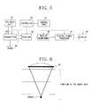
- FIG. 5 is a schematic block diagram showing an ultrasonic imaging system embodying an optimum harmonic image according to the present invention.
- the operation for a fundamental image realization mode is the same as that in the above-described FIG. 3 system. Accordingly, the detailed description thereof will be omitted herein.
- a controller 50 controls an optimum harmonic imaging (OHI) mode unit 52 in correspondence to entry of the harmonic mode key.
- the OHI mode unit 52 outputs data with respect to velocities of the ultrasonic wave depending upon the medium in the human body which are stored therein, to a digital signal processor 57.
- the digital signal processor 57 performs a signal processing so that the received data is displayed on a monitor and outputs the signal processed result to a display 58.
- the display 58 which has received the data from the digital signal processor 57 displays the velocities of the ultrasonic wave depending upon the medium in the human body.
- the user selects a velocity of an ultrasonic wave which is the most appropriate for the medium in the human body where a harmonic image is desired to be obtained, among the ultrasonic velocities depending upon the medium in the human body which are displayed on the display 58, using a select key provided on the control panel 51.
- the OHI mode unit 52 outputs a control signal to a transmitter 53 and a receiver 55, in such a manner that a transmission pulse depending upon the selected ultrasonic velocity and a predetermined frequency is applied to a probe 54 and a harmonic signal depending upon the transmitted ultrasonic wave is separated from the ultrasonic reception signal reflected and returning from the human body, to then perform a signal processing.
- the transmitter 53 which has received the control signal from the OHI mode unit 52 applies the transmission pulse depending upon the received control signal to the probe 54.
- the probe 54 transmits the ultrasonic wave depending upon the transmission pulse received from the transmitter 53, into the human body and receives the returning signal reflected from the human body.
- the received ultrasonic reception signal is input to the receiver 55.
- the receiver 55 separates a harmonic signal depending upon the transmitted ultrasonic wave from the ultrasonic reception signal according to the control signal applied from the OHI mode unit 52.
- the receiver 55 performs a control, filtering, TGC, etc., for reception beamforming with respect to the separated harmonic signal.
- a receive beamforrner 56 receives the signal-processed signal from the receiver 55 and performs a reception beamforming (dynamic focusing or synthetic focusing) of the received signal, to then output the reception beamformed signal.
- a digital signal processor 57 performs a digital signal processing in order to obtain a harmonic image from the signal beamformed in the receive beamformer 56.
- a display 58 receives a signal processed signal from the digital signal processor 57 and displays a harmonic image with respect to the ultrasonic reception signal thereon.
- the ultrasonic wave transmitted from the probe 54 into the medium in the human body is accurately focused on a point (target) where an ultrasonic image is desired to be obtained and a reflected signal is returned to the probe 54 therefrom.
- a point target
- an accurate ultrasonic image is obtained with respect to the target.
- an ultrasonic wave having the most appropriate velocity for the medium in the human body where a harmonic image is desired to be obtained is transmitted into the human body and then a returning signal reflected from the medium is received.
- an optimum harmonic image which reduces an artifact generated at the time of transmitting and receiving an ultrasonic wave and has further improved contrast and lateral resolutions can be obtained.
- the velocity of an ultrasonic wave which is the most appropriate for the medium in the human body is selected according to the above-described procedure, and the ultrasonic wave of the selected velocity is transmitted into the human body and reflected therefrom and then received. In this way, an optimum harmonic image is obtained with respect to the medium in the human body.
- the ultrasonic imaging system for realizing the optimum harmonic image and the method therefor according to the present invention can obtain a harmonic image having a reduced artifact and further improved contrast and lateral resolutions, by varying an ultrasonic velocity used for processing an ultrasonic signal, which is transmitted into a human body and is reflected therefrom according to the medium in the human body which is desired to be obtained.
Landscapes
- Engineering & Computer Science (AREA)
- Physics & Mathematics (AREA)
- Health & Medical Sciences (AREA)
- Life Sciences & Earth Sciences (AREA)
- Computer Networks & Wireless Communication (AREA)
- Remote Sensing (AREA)
- Radar, Positioning & Navigation (AREA)
- General Physics & Mathematics (AREA)
- Radiology & Medical Imaging (AREA)
- Nonlinear Science (AREA)
- Medical Informatics (AREA)
- Molecular Biology (AREA)
- Surgery (AREA)
- Animal Behavior & Ethology (AREA)
- General Health & Medical Sciences (AREA)
- Public Health (AREA)
- Veterinary Medicine (AREA)
- Heart & Thoracic Surgery (AREA)
- Biomedical Technology (AREA)
- Pathology (AREA)
- Nuclear Medicine, Radiotherapy & Molecular Imaging (AREA)
- Biophysics (AREA)
- Ultra Sonic Daignosis Equipment (AREA)
- Measurement Of Velocity Or Position Using Acoustic Or Ultrasonic Waves (AREA)
- Investigating Or Analyzing Materials By The Use Of Ultrasonic Waves (AREA)
Applications Claiming Priority (2)
| Application Number | Priority Date | Filing Date | Title |
|---|---|---|---|
| KR9908744 | 1999-03-16 | ||
| KR1019990008744A KR20000060441A (ko) | 1999-03-16 | 1999-03-16 | 최적의 하모닉영상(ohi)을 구현하는 초음파영상시스템 및 그 방법 |
Publications (2)
| Publication Number | Publication Date |
|---|---|
| EP1039312A2 true EP1039312A2 (fr) | 2000-09-27 |
| EP1039312A3 EP1039312A3 (fr) | 2002-09-25 |
Family
ID=19576659
Family Applications (1)
| Application Number | Title | Priority Date | Filing Date |
|---|---|---|---|
| EP99125028A Withdrawn EP1039312A3 (fr) | 1999-03-16 | 1999-12-15 | Système et méthode d'imagerie à ultrasons pour réaliser une image harmonique optimalisée |
Country Status (3)
| Country | Link |
|---|---|
| EP (1) | EP1039312A3 (fr) |
| JP (1) | JP2000262521A (fr) |
| KR (1) | KR20000060441A (fr) |
Cited By (2)
| Publication number | Priority date | Publication date | Assignee | Title |
|---|---|---|---|---|
| EP2047802A1 (fr) * | 2007-10-11 | 2009-04-15 | Fujifilm Corporation | Procédé et appareil de diagnostic ultrasonique |
| WO2012146946A1 (fr) * | 2011-04-29 | 2012-11-01 | B-K Medical Aps | Imagerie ultrasonore harmonique à l'aide d'une formation de faisceau séquentielle à ouverture synthétique |
Families Citing this family (1)
| Publication number | Priority date | Publication date | Assignee | Title |
|---|---|---|---|---|
| KR100392094B1 (ko) * | 2001-09-11 | 2003-07-22 | 주식회사 메디슨 | 초음파 영상 최적화 시스템 |
Family Cites Families (10)
| Publication number | Priority date | Publication date | Assignee | Title |
|---|---|---|---|---|
| DE3127146A1 (de) * | 1981-07-09 | 1983-01-27 | Siemens AG, 1000 Berlin und 8000 München | Verfahren zur korrektur von durch laufzeiteffekte verursachten bildfehlern bei der ultraschall-abbildung von objekten, insbesondere bei der ultraschall-reflexions-computer-tomographie und bei dem compound-b-scan-verfahren |
| JP3403809B2 (ja) * | 1993-06-14 | 2003-05-06 | 株式会社東芝 | 超音波診断装置 |
| US5526816A (en) * | 1994-09-22 | 1996-06-18 | Bracco Research S.A. | Ultrasonic spectral contrast imaging |
| JP3682088B2 (ja) * | 1995-04-27 | 2005-08-10 | 株式会社東芝 | 超音波診断装置 |
| JP3642607B2 (ja) * | 1995-05-26 | 2005-04-27 | 株式会社日立メディコ | 超音波断層装置 |
| US5566675A (en) * | 1995-06-30 | 1996-10-22 | Siemens Medical Systems, Inc. | Beamformer for phase aberration correction |
| JP3510032B2 (ja) * | 1996-01-12 | 2004-03-22 | ジーイー横河メディカルシステム株式会社 | 超音波撮像装置 |
| JPH1014921A (ja) * | 1996-07-08 | 1998-01-20 | Ge Yokogawa Medical Syst Ltd | 超音波イメージング方法及び超音波イメージング装置 |
| JP4382884B2 (ja) * | 1996-11-08 | 2009-12-16 | コーニンクレッカ フィリップス エレクトロニクス エヌ ヴィ | 高調波による超音波画像処理方法および装置 |
| US6050944A (en) * | 1997-06-17 | 2000-04-18 | Acuson Corporation | Method and apparatus for frequency control of an ultrasound system |
-
1999
- 1999-03-16 KR KR1019990008744A patent/KR20000060441A/ko not_active Ceased
- 1999-12-15 EP EP99125028A patent/EP1039312A3/fr not_active Withdrawn
- 1999-12-24 JP JP11366821A patent/JP2000262521A/ja active Pending
Cited By (3)
| Publication number | Priority date | Publication date | Assignee | Title |
|---|---|---|---|---|
| EP2047802A1 (fr) * | 2007-10-11 | 2009-04-15 | Fujifilm Corporation | Procédé et appareil de diagnostic ultrasonique |
| WO2012146946A1 (fr) * | 2011-04-29 | 2012-11-01 | B-K Medical Aps | Imagerie ultrasonore harmonique à l'aide d'une formation de faisceau séquentielle à ouverture synthétique |
| US20140050048A1 (en) * | 2011-04-29 | 2014-02-20 | B-K Medical Aps | Harmonic Ultrasound Imaging Using Synthetic Aperture Sequential Beamforming |
Also Published As
| Publication number | Publication date |
|---|---|
| JP2000262521A (ja) | 2000-09-26 |
| KR20000060441A (ko) | 2000-10-16 |
| EP1039312A3 (fr) | 2002-09-25 |
Similar Documents
| Publication | Publication Date | Title |
|---|---|---|
| US5910115A (en) | Method and apparatus for coherence filtering of ultrasound images | |
| KR100749973B1 (ko) | Prf 조절 방법 및 장치, 및 초음파 촬상 장치 | |
| US6176830B1 (en) | Method and system for pre-determining spectral doppler user parameters | |
| US5882306A (en) | Ultrasound imaging methods and systems | |
| JP3251696B2 (ja) | 超音波診断装置 | |
| US6322510B1 (en) | Ultrasonic imaging method and apparatus | |
| US6599248B1 (en) | Method and apparatus for ultrasound diagnostic imaging | |
| US6503200B2 (en) | Ultrasonic diagnostic apparatus | |
| JP4117383B2 (ja) | 超音波撮影装置 | |
| JPH1071146A (ja) | 動作諸元表示方法および装置並びに超音波映像装置 | |
| JPS62201144A (ja) | アレイ探触子の駆動方法 | |
| EP4139058B1 (fr) | Sonde d'imagerie acoustique comportant un élément de transducteur | |
| JP3308587B2 (ja) | 超音波診断装置 | |
| US6290647B1 (en) | Contrast agent imaging with subharmonic and harmonic signals in diagnostic medical ultrasound | |
| JP3468431B2 (ja) | 穿刺機構付き超音波診断装置 | |
| JP2760550B2 (ja) | 超音波診断装置 | |
| KR20000060441A (ko) | 최적의 하모닉영상(ohi)을 구현하는 초음파영상시스템 및 그 방법 | |
| JP3472604B2 (ja) | 超音波ドプラ診断装置 | |
| JP2782905B2 (ja) | 超音波診断装置 | |
| EP4055413B1 (fr) | Cathéter d'imagerie à ultrasons | |
| JP3500014B2 (ja) | 超音波診断装置 | |
| US12471879B2 (en) | Methods and systems for obtaining a 3D vector flow field | |
| JP4318772B2 (ja) | 超音波診断装置 | |
| JP2679200B2 (ja) | ドプラ断層超音波診断装置 | |
| JPH0710728Y2 (ja) | ドプラ断層超音波診断装置 |
Legal Events
| Date | Code | Title | Description |
|---|---|---|---|
| PUAI | Public reference made under article 153(3) epc to a published international application that has entered the european phase |
Free format text: ORIGINAL CODE: 0009012 |
|
| AK | Designated contracting states |
Kind code of ref document: A2 Designated state(s): AT BE CH CY DE DK ES FI FR GB GR IE IT LI LU MC NL PT SE |
|
| AX | Request for extension of the european patent |
Free format text: AL;LT;LV;MK;RO;SI |
|
| PUAL | Search report despatched |
Free format text: ORIGINAL CODE: 0009013 |
|
| RIC1 | Information provided on ipc code assigned before grant |
Free format text: 7G 01S 7/52 A, 7G 01S 15/89 B |
|
| AK | Designated contracting states |
Kind code of ref document: A3 Designated state(s): AT BE CH CY DE DK ES FI FR GB GR IE IT LI LU MC NL PT SE |
|
| AX | Request for extension of the european patent |
Free format text: AL;LT;LV;MK;RO;SI |
|
| 17P | Request for examination filed |
Effective date: 20030307 |
|
| 17Q | First examination report despatched |
Effective date: 20030403 |
|
| AKX | Designation fees paid |
Designated state(s): DE FR GB IT NL |
|
| STAA | Information on the status of an ep patent application or granted ep patent |
Free format text: STATUS: THE APPLICATION IS DEEMED TO BE WITHDRAWN |
|
| 18D | Application deemed to be withdrawn |
Effective date: 20030814 |