EP1039355A1 - Verfahren zur Herstellung von Anzeigeorganen für Uhren und nach diesem Verfahren hergestelltes Anzeigeorgan - Google Patents
Verfahren zur Herstellung von Anzeigeorganen für Uhren und nach diesem Verfahren hergestelltes Anzeigeorgan Download PDFInfo
- Publication number
- EP1039355A1 EP1039355A1 EP99105905A EP99105905A EP1039355A1 EP 1039355 A1 EP1039355 A1 EP 1039355A1 EP 99105905 A EP99105905 A EP 99105905A EP 99105905 A EP99105905 A EP 99105905A EP 1039355 A1 EP1039355 A1 EP 1039355A1
- Authority
- EP
- European Patent Office
- Prior art keywords
- thermoforming
- strip
- ring
- display member
- sheet
- Prior art date
- Legal status (The legal status is an assumption and is not a legal conclusion. Google has not performed a legal analysis and makes no representation as to the accuracy of the status listed.)
- Granted
Links
- 238000000034 method Methods 0.000 title claims abstract description 32
- 238000004519 manufacturing process Methods 0.000 title claims description 19
- 210000000056 organ Anatomy 0.000 title description 17
- 238000003856 thermoforming Methods 0.000 claims abstract description 30
- 238000005520 cutting process Methods 0.000 claims abstract description 19
- 239000002985 plastic film Substances 0.000 claims abstract description 5
- 230000000295 complement effect Effects 0.000 claims abstract description 3
- 230000006835 compression Effects 0.000 claims 1
- 238000007906 compression Methods 0.000 claims 1
- 239000004033 plastic Substances 0.000 abstract description 25
- 239000000463 material Substances 0.000 description 15
- 239000003973 paint Substances 0.000 description 6
- 239000002184 metal Substances 0.000 description 5
- 238000003860 storage Methods 0.000 description 5
- 230000000750 progressive effect Effects 0.000 description 4
- 238000002347 injection Methods 0.000 description 3
- 239000007924 injection Substances 0.000 description 3
- 239000004519 grease Substances 0.000 description 2
- BASFCYQUMIYNBI-UHFFFAOYSA-N platinum Chemical compound [Pt] BASFCYQUMIYNBI-UHFFFAOYSA-N 0.000 description 2
- 238000000926 separation method Methods 0.000 description 2
- FGRBYDKOBBBPOI-UHFFFAOYSA-N 10,10-dioxo-2-[4-(N-phenylanilino)phenyl]thioxanthen-9-one Chemical compound O=C1c2ccccc2S(=O)(=O)c2ccc(cc12)-c1ccc(cc1)N(c1ccccc1)c1ccccc1 FGRBYDKOBBBPOI-UHFFFAOYSA-N 0.000 description 1
- PEDCQBHIVMGVHV-UHFFFAOYSA-N Glycerine Chemical compound OCC(O)CO PEDCQBHIVMGVHV-UHFFFAOYSA-N 0.000 description 1
- 229920000297 Rayon Polymers 0.000 description 1
- 239000003086 colorant Substances 0.000 description 1
- 230000000994 depressogenic effect Effects 0.000 description 1
- 239000000428 dust Substances 0.000 description 1
- 230000000694 effects Effects 0.000 description 1
- 239000011888 foil Substances 0.000 description 1
- 239000011159 matrix material Substances 0.000 description 1
- 238000010422 painting Methods 0.000 description 1
- 230000002093 peripheral effect Effects 0.000 description 1
- 238000007747 plating Methods 0.000 description 1
- 238000003908 quality control method Methods 0.000 description 1
- 239000002964 rayon Substances 0.000 description 1
- 230000009182 swimming Effects 0.000 description 1
- 238000005406 washing Methods 0.000 description 1
Images



Classifications
-
- G—PHYSICS
- G04—HOROLOGY
- G04B—MECHANICALLY-DRIVEN CLOCKS OR WATCHES; MECHANICAL PARTS OF CLOCKS OR WATCHES IN GENERAL; TIME PIECES USING THE POSITION OF THE SUN, MOON OR STARS
- G04B19/00—Indicating the time by visual means
- G04B19/06—Dials
- G04B19/12—Selection of materials for dials or graduations markings
-
- G—PHYSICS
- G04—HOROLOGY
- G04D—APPARATUS OR TOOLS SPECIALLY DESIGNED FOR MAKING OR MAINTAINING CLOCKS OR WATCHES
- G04D3/00—Watchmakers' or watch-repairers' machines or tools for working materials
- G04D3/0002—Watchmakers' or watch-repairers' machines or tools for working materials for mechanical working other than with a lathe
- G04D3/0043—Watchmakers' or watch-repairers' machines or tools for working materials for mechanical working other than with a lathe for components of the time-indicating mechanisms
Definitions
- the present invention relates to a process for mass production a display member for a timepiece and a member display manufactured by this process.
- display device must be taken here under its acceptance the widest. It can be a dial, a date disc or even of moving figurines showing, for example, moon phases, provided however that these supplies have an uneven profile and therefore not flat. To manufacture such parts in series, it is therefore not only to cut them out of a strip, but to form them, before cutting, according to a profile suitable for their functions.
- the document CH 544 332 also describes a method for manufacture a date indicator entirely made of plastic.
- the plastic injection technique is implemented.
- reading the document shows that great care must be taken to inject a disc whose thickness is around 0.3 mm, both for the choice of material only for making the mold. This therefore leads to a expensive part to manufacture and even impossible to manufacture if the thickness of the disc should be 0.15mm, as may be the case for the disc made using the method of the present invention.
- step c) which consists of making at least one cut in the inner part of the display member
- step e) which consists in affixing indications on said display member.
- the present invention also relates to a display member executed according to the process described above, the description which follows will apply especially to describe a date disc.
- thermoforming To manufacture a display member such as, for example, a disc date as shown in Figures 1 and 2, a dial such as shown in Figures 3, 4 and 5, or even any figurine, we can use a metallic foil or injection of material plastic as mentioned in the preamble to this document. For eliminate the disadvantages of such methods listed in the same preamble, the present invention proposes the use of thermoforming.
- a plastic sheet shaped into a strip 3 has a sufficient dimension to manufacture at least one member display.
- the plastic used in this process must be chosen to be suitable for thermoforming, for example a material of PET type. The color of this material will be chosen so that there is no no need to paint the object, so that inscriptions can be directly affixed at the end of the process.
- Strip 3 is fitted with pilot holes 5 perforated by a machine recalling a progressive stamp which will successively take care of all stages of manufacturing.
- the pilot holes 5 thus make it possible to center the strip exactly between the various molds, stamps or printing devices which appear one after the other in the progressive stamp.
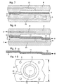
- thermoforming operation For that the strip 3, as shown in Figures 7 and 8, is inserted between two tools 4 and 6 which allow such an operation according to various methods which will be described below.
- the thermoforming operation gives the organ display profile B as shown in figure 8.
- the strip comes out of tools 4 and 6 with an uneven, non-flat surface, profile B, as shown in figure 9.
- the display device described above is circular. Of course he could take other forms to make for example figurines of any species that can be found on a timepiece. This is actually a display unit produced according to the most general acceptance of the invention, namely a display member from a strip of material plastic, then thermoformed, then cut from this strip. We will see by further additional operations are required if you want manufacture more complex display elements such as, for example, a date disc or a dial.
- thermoforming is known per se. It is used for medium or large objects such as, for example, food containers or swimming pools.
- the interested reader will read profitably the brochures of the company Adolf Illig, Heilbronn, Germany, specialist in topic.
- Adolf Illig, Heilbronn, Germany specialist in topic.
- it has never been proposed so far to manufacture this way of small objects, in particular display units for rooms of watchmaking. In watchmaking, this method has so far enjoyed unfavorable prejudice because of the very thin plastic sheets it puts in action. How indeed dare to offer a date disc which the thickness of the teeth hardly exceeds 0.15 mm?
- thermoform a sheet by plastic material There are several ways to thermoform a sheet by plastic material.
- FIGS 7 and 8 Thermoforming by air pressure is shown in Figures 7 and 8.
- a portion of the sheet 3 to be thermoformed is taken between two tools 4 and 6. This portion is heated beforehand and then injected, in the direction of the arrow E of the air in a channel 21 which is part of the tool 4. The air pressure then forces the sheet 3 to be applied to the bottom of the tool 6, this tool is presenting like a mold whose bottom has the desired profile give to the room.
- a channel 22 is provided for evacuating the air between the sheet and the bottom of the mold 6, and this in the direction of the arrow F.
- Vacuum thermoforming or air suction is also shown to Figures 7 and 8. After having arranged and heated the sheet 3 between the tools 4 and 6, the air contained between the sheet and the bottom is sucked in, in the direction of the arrow F of the tool 6. This suction forces the sheet 3 to come to be applied to the bottom of the tool 6 which is presented as a mold whose bottom has the desired profile give to the room. A channel 21 allows air to enter the tool 4 to this operation and this according to arrow E.
- thermoforming Note that tools 4 and 6 shown here for the two operations thermoforming are very rudimentary and are only a draft for explain the principle of this thermoforming.
- thermoforming There is yet another way to distort a sheet by thermoforming. This is to compress the sheet previously heated between two complementary molds with the desired profile. This method taken for granted, we did not consider it useful to represent it here.
- disc 1 and the dial 2 are generally provided graphic indications (dates, brands, etc.), we will understand, without being necessary to illustrate this operation, that these indications will be affixed on the strip at least before the operation which separates the display member 1 or 2 of strip 3.
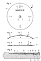
- These inscriptions consist for disc 1 of date indications 8 (figure 1) and for dial 2 an indication of mark 27 (figure 3). Note that for dial 2, these indications could be hour digits.
- These indications are transferred on the organ by means of a printing device which is part of the stamp progressive.
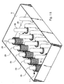
- Figure 15 shows a magazine 9 that can receive a large quantity of display elements. So far there has been talk of a tape 3 made plastic material whose width A has a sufficient dimension to manufacture at least one display member (see Figures 10 and 12). We can however imagine a bandwidth 3 sized to manufacture in at the same time, several display members facing each other.
- the tray 9 in figure 15 shows that the plastic strip is wide enough to make five frontal organs, these five organs being produced at the same time and each falling simultaneously on cylindrical pads 29 arranged in alignment perpendicular to the direction of the web.
- Figure 15 shows that after stacked enough organs 1 on each of the pads 29, the magazine 9 one step forward under the progressive stamp, organs 1 then starting to be stacked on the studs 30 and so on.
- Such storage is advantageous for all the reasons mentioned above. We will mention also that it significantly reduces the handling time and organ quality control as well as storage volume.
- this store can contain 5,000 organs display panels arranged in perfect order and even protected from dust if it has a cover. Such an arrangement makes it possible to reduce the volume of storage of about two-thirds of that taken by the conventional system of bulk storage.
- the display member 1 shown in perspective in Figure 1 and in section in Figure 2 is a date disc.
- This disc has a first outer ring 10 cut from the strip according to the contour 20. On this ring 10 are affixed with indications 8 relating to the date, plus precisely numbers from 1 to 31.
- Disc 1 still has a second ring 11 attached to the first and disposed lower than this first as shown in Figure 2. This depressed layout of the second ring 11 defines a space 12 suitable for receiving a disc of the days of the week.
- the disc 1 finally comprises a third ring 13 attached to the second and arranged lower than this second as is always good visible in Figure 2. An internal toothing 16 is cut in the third ring 13 to ensure the drive of the disc.
- Disc 1 is therefore presents in the form of stairs whose profile is produced by thermoforming as seen above.
- the thickness of the disc 1 and therefore of its successive stairs 10, 11 and 13 and the teeth 14 is of the order of 0.15 mm. This gives a very light disc which can easily be driven by its teeth which proved to be sufficiently robust despite their small thickness.
- Figure 6 is a section through a plate 15 of a timepiece. This plate supports the disc 1 manufactured according to the invention.
- Figure 6 shows that the third ring 13 of the disc 1 rests on a thread 14 presented by the plate 15. Since the disc 1 is made of plastic, there is no therefore not take place, as would be the case if this disc were made of metal, grease where the ring 13 rubs on the thread 14.
- Figure 6 again shows space 12 reserved for the weekdays disc as well as the star 32 which causes the teeth 16 of the disc 1.
- the rings successive 10, 11 and 13 form natural ribs 33 and 34 which stiffen the disc and force it to remain flat, so that friction does not take place only under the ring 13 thus minimizing the friction torque exerted on the disk.
- the display member shown in plan in Figure 3 and in section at Figures 4 and 5 is a dial 2.
- This dial 2 is made of plastic and has a contour 17 cut from the strip.
- This dial has a interior cutout 7 showing a central opening 18 from which the axes supporting the needles emerge.
- Drops 19, forming index hours, are lifted from dial 2 and are produced by thermoforming according to one of the methods described above.
- the sections in Figures 4 and 5 show well how the drops are made 19.
- the dial 2 can be rounded as shown in Figure 4, this convex being also obtained by thermoforming, or flat as shown in Figure 5.
- a mark 27 can be transferred onto the dial 2 according to the process described above.
- the dial could carry other transferred inscriptions such as for example hour markers or colors marking the drops 19 more pronounced.
Landscapes
- Physics & Mathematics (AREA)
- General Physics & Mathematics (AREA)
- Blow-Moulding Or Thermoforming Of Plastics Or The Like (AREA)
Priority Applications (2)
| Application Number | Priority Date | Filing Date | Title |
|---|---|---|---|
| DE69939973T DE69939973D1 (de) | 1999-03-24 | 1999-03-24 | Verfahren zur Herstellung von Anzeigeorganen für Uhren und nach diesem Verfahren hergestelltes Anzeigeorgan |
| EP19990105905 EP1039355B1 (de) | 1999-03-24 | 1999-03-24 | Verfahren zur Herstellung von Anzeigeorganen für Uhren und nach diesem Verfahren hergestelltes Anzeigeorgan |
Applications Claiming Priority (1)
| Application Number | Priority Date | Filing Date | Title |
|---|---|---|---|
| EP19990105905 EP1039355B1 (de) | 1999-03-24 | 1999-03-24 | Verfahren zur Herstellung von Anzeigeorganen für Uhren und nach diesem Verfahren hergestelltes Anzeigeorgan |
Publications (2)
| Publication Number | Publication Date |
|---|---|
| EP1039355A1 true EP1039355A1 (de) | 2000-09-27 |
| EP1039355B1 EP1039355B1 (de) | 2008-11-26 |
Family
ID=8237845
Family Applications (1)
| Application Number | Title | Priority Date | Filing Date |
|---|---|---|---|
| EP19990105905 Expired - Lifetime EP1039355B1 (de) | 1999-03-24 | 1999-03-24 | Verfahren zur Herstellung von Anzeigeorganen für Uhren und nach diesem Verfahren hergestelltes Anzeigeorgan |
Country Status (2)
| Country | Link |
|---|---|
| EP (1) | EP1039355B1 (de) |
| DE (1) | DE69939973D1 (de) |
Citations (7)
| Publication number | Priority date | Publication date | Assignee | Title |
|---|---|---|---|---|
| CH294056A (fr) * | 1951-12-03 | 1953-10-31 | Piquerez Erwin | Procédé de fabrication d'un cadran, notamment pour pièce d'horlogerie. |
| FR1044497A (fr) * | 1951-11-06 | 1953-11-17 | Cadrhor | Cadran, notamment pour montres et pendulettes |
| CH623668A4 (de) * | 1968-04-26 | 1971-03-31 | ||
| CH544332A (de) | 1971-08-02 | 1973-05-30 | Suzuki Risuke | Verfahren zur Herstellung dünner Kunststoffskalenscheiben, insbesondere Kunststoffdatumsrädern, für Uhren |
| CH554554A (de) | 1972-07-05 | 1974-09-30 | ||
| GB2094701A (en) * | 1981-02-05 | 1982-09-22 | Matsushita Electric Industrial Co Ltd | Speaker diaphragm and method of manufacture |
| EP0791414A1 (de) * | 1996-02-26 | 1997-08-27 | Karl Marbach GmbH + Co. | Stanz- und Formwerkzeug |
-
1999
- 1999-03-24 DE DE69939973T patent/DE69939973D1/de not_active Expired - Lifetime
- 1999-03-24 EP EP19990105905 patent/EP1039355B1/de not_active Expired - Lifetime
Patent Citations (7)
| Publication number | Priority date | Publication date | Assignee | Title |
|---|---|---|---|---|
| FR1044497A (fr) * | 1951-11-06 | 1953-11-17 | Cadrhor | Cadran, notamment pour montres et pendulettes |
| CH294056A (fr) * | 1951-12-03 | 1953-10-31 | Piquerez Erwin | Procédé de fabrication d'un cadran, notamment pour pièce d'horlogerie. |
| CH623668A4 (de) * | 1968-04-26 | 1971-03-31 | ||
| CH544332A (de) | 1971-08-02 | 1973-05-30 | Suzuki Risuke | Verfahren zur Herstellung dünner Kunststoffskalenscheiben, insbesondere Kunststoffdatumsrädern, für Uhren |
| CH554554A (de) | 1972-07-05 | 1974-09-30 | ||
| GB2094701A (en) * | 1981-02-05 | 1982-09-22 | Matsushita Electric Industrial Co Ltd | Speaker diaphragm and method of manufacture |
| EP0791414A1 (de) * | 1996-02-26 | 1997-08-27 | Karl Marbach GmbH + Co. | Stanz- und Formwerkzeug |
Also Published As
| Publication number | Publication date |
|---|---|
| DE69939973D1 (de) | 2009-01-08 |
| EP1039355B1 (de) | 2008-11-26 |
Similar Documents
| Publication | Publication Date | Title |
|---|---|---|
| EP0231670A1 (de) | Verfahren zum Herstellen von Gegenständen durch Spritzgiessen eines Kunststoffes auf einen aus einem Streifen gestanzten Filmausschnitt und Vorrichtung zur Durchführung des Verfahrens | |
| CA2220540A1 (fr) | Piece comportant un corps moule et un element decoratif incruste et procede de fabrication de cette piece | |
| EP2717437A1 (de) | Elektromagnetischer Motor für elektronisches Uhrwerk mit Analoganzeige | |
| EP1039355B1 (de) | Verfahren zur Herstellung von Anzeigeorganen für Uhren und nach diesem Verfahren hergestelltes Anzeigeorgan | |
| EP0994398B1 (de) | Verfahren zur Herstellung eines Zahnrades für eine Uhr sowie ein nach diesem Verfahren hergestelltes Zahnrad | |
| BE1004332A6 (fr) | Methode de fabrication d'une feuille continue d'etiquettes et appareil prevu a cet effet. | |
| EP0847546A1 (de) | Verfahren zum giessen und zum anbringen von markierungen auf einer fläche | |
| KR100703244B1 (ko) | 시계용 표시 요소의 제작 방법 및 상기 방법에 따라제작된 표시 요소 | |
| FR2609448A3 (fr) | Dispositif de prelevement, sur piles de plateaux, de plateaux individuels flexibles | |
| EP1559832B1 (de) | Verfahren zum einsetzen von chips in eine faserbahn | |
| EP0565434B1 (de) | Verfahren und Vorrichtung zur Herstellung von Kennzeichenschildern, insbesondere reflektierenden Schildern | |
| EP0917686A1 (de) | Herstellungsverfahren für speicherkarten und nach diesem verfahren hergestellte karten | |
| EP1168281A1 (de) | Etikett für Lebensmittelprodukte | |
| FR2810099A1 (fr) | Procede de fabrication d'un disque diffuseur pour un dispositif de signaux lumineux | |
| FR2827805A1 (fr) | Procede de decoration d'une piece en matiere plastique | |
| FR2771333A1 (fr) | Procede et machines pour le rainage et le decoupage en ligne d'un format brut destine a la formation d'emballages en carton | |
| BE1013831A6 (fr) | Systeme d'etiquetage pour disque a lecture optique. | |
| EP0105841A1 (de) | Werkstreifen zur Herstellung von Komponententrägern für Uhren | |
| EP4360833A1 (de) | Handperforiermaschine | |
| CH349276A (fr) | Cartouche d'emballage d'un ruban d'impression encré et procédé pour sa fabrication | |
| FR2479743A1 (fr) | Roue de positionnement et dispositif d'impression la comportant | |
| CH355609A (fr) | Moule à empreintes multiples | |
| BE510634A (de) | ||
| WO2002081326A1 (fr) | Ensemble de distribution de produit fluide | |
| EP1045365A1 (de) | Eingekapselte Magnet für Anzeigetafel und Herstellungsverfahren desselben |
Legal Events
| Date | Code | Title | Description |
|---|---|---|---|
| PUAI | Public reference made under article 153(3) epc to a published international application that has entered the european phase |
Free format text: ORIGINAL CODE: 0009012 |
|
| AK | Designated contracting states |
Kind code of ref document: A1 Designated state(s): CH DE FR GB LI |
|
| AX | Request for extension of the european patent |
Free format text: AL;LT;LV;MK;RO;SI |
|
| 17P | Request for examination filed |
Effective date: 20010327 |
|
| AKX | Designation fees paid |
Free format text: CH DE FR GB LI |
|
| RAP1 | Party data changed (applicant data changed or rights of an application transferred) |
Owner name: ETA SA MANUFACTURE HORLOGERE SUISSE |
|
| 17Q | First examination report despatched |
Effective date: 20070531 |
|
| GRAP | Despatch of communication of intention to grant a patent |
Free format text: ORIGINAL CODE: EPIDOSNIGR1 |
|
| GRAS | Grant fee paid |
Free format text: ORIGINAL CODE: EPIDOSNIGR3 |
|
| GRAA | (expected) grant |
Free format text: ORIGINAL CODE: 0009210 |
|
| AK | Designated contracting states |
Kind code of ref document: B1 Designated state(s): CH DE FR GB LI |
|
| REG | Reference to a national code |
Ref country code: GB Ref legal event code: FG4D Free format text: NOT ENGLISH |
|
| REG | Reference to a national code |
Ref country code: CH Ref legal event code: EP |
|
| REF | Corresponds to: |
Ref document number: 69939973 Country of ref document: DE Date of ref document: 20090108 Kind code of ref document: P |
|
| REG | Reference to a national code |
Ref country code: CH Ref legal event code: NV Representative=s name: ICB INGENIEURS CONSEILS EN BREVETS SA |
|
| PGFP | Annual fee paid to national office [announced via postgrant information from national office to epo] |
Ref country code: GB Payment date: 20090225 Year of fee payment: 11 |
|
| PLBE | No opposition filed within time limit |
Free format text: ORIGINAL CODE: 0009261 |
|
| STAA | Information on the status of an ep patent application or granted ep patent |
Free format text: STATUS: NO OPPOSITION FILED WITHIN TIME LIMIT |
|
| 26N | No opposition filed |
Effective date: 20090827 |
|
| PGFP | Annual fee paid to national office [announced via postgrant information from national office to epo] |
Ref country code: CH Payment date: 20100219 Year of fee payment: 12 |
|
| PGFP | Annual fee paid to national office [announced via postgrant information from national office to epo] |
Ref country code: FR Payment date: 20100419 Year of fee payment: 12 |
|
| PGFP | Annual fee paid to national office [announced via postgrant information from national office to epo] |
Ref country code: DE Payment date: 20100302 Year of fee payment: 12 |
|
| GBPC | Gb: european patent ceased through non-payment of renewal fee |
Effective date: 20100324 |
|
| PG25 | Lapsed in a contracting state [announced via postgrant information from national office to epo] |
Ref country code: GB Free format text: LAPSE BECAUSE OF NON-PAYMENT OF DUE FEES Effective date: 20100324 |
|
| REG | Reference to a national code |
Ref country code: CH Ref legal event code: PL |
|
| REG | Reference to a national code |
Ref country code: FR Ref legal event code: ST Effective date: 20111130 |
|
| PG25 | Lapsed in a contracting state [announced via postgrant information from national office to epo] |
Ref country code: DE Free format text: LAPSE BECAUSE OF NON-PAYMENT OF DUE FEES Effective date: 20111001 Ref country code: CH Free format text: LAPSE BECAUSE OF NON-PAYMENT OF DUE FEES Effective date: 20110331 Ref country code: LI Free format text: LAPSE BECAUSE OF NON-PAYMENT OF DUE FEES Effective date: 20110331 Ref country code: FR Free format text: LAPSE BECAUSE OF NON-PAYMENT OF DUE FEES Effective date: 20110331 |
|
| REG | Reference to a national code |
Ref country code: DE Ref legal event code: R119 Ref document number: 69939973 Country of ref document: DE Effective date: 20111001 |