EP1039660A2 - Réseau sans fils avec synchronisation d'utilisateur - Google Patents
Réseau sans fils avec synchronisation d'utilisateur Download PDFInfo
- Publication number
- EP1039660A2 EP1039660A2 EP00200851A EP00200851A EP1039660A2 EP 1039660 A2 EP1039660 A2 EP 1039660A2 EP 00200851 A EP00200851 A EP 00200851A EP 00200851 A EP00200851 A EP 00200851A EP 1039660 A2 EP1039660 A2 EP 1039660A2
- Authority
- EP
- European Patent Office
- Prior art keywords
- network node
- time
- user
- value
- network
- Prior art date
- Legal status (The legal status is an assumption and is not a legal conclusion. Google has not performed a legal analysis and makes no representation as to the accuracy of the status listed.)
- Withdrawn
Links
- 238000012937 correction Methods 0.000 claims description 25
- 230000005540 biological transmission Effects 0.000 claims description 17
- 238000012545 processing Methods 0.000 claims description 5
- 241000772415 Neovison vison Species 0.000 claims description 4
- 238000012432 intermediate storage Methods 0.000 claims 1
- 238000003860 storage Methods 0.000 claims 1
- 238000000034 method Methods 0.000 description 13
- 230000006870 function Effects 0.000 description 10
- 230000001360 synchronised effect Effects 0.000 description 10
- 238000012935 Averaging Methods 0.000 description 9
- 230000008569 process Effects 0.000 description 6
- 230000015572 biosynthetic process Effects 0.000 description 5
- 238000001514 detection method Methods 0.000 description 4
- 230000001960 triggered effect Effects 0.000 description 3
- 238000010586 diagram Methods 0.000 description 2
- 230000000694 effects Effects 0.000 description 2
- 230000006978 adaptation Effects 0.000 description 1
- 230000008901 benefit Effects 0.000 description 1
- 230000008859 change Effects 0.000 description 1
- 238000010276 construction Methods 0.000 description 1
- 230000003247 decreasing effect Effects 0.000 description 1
- 238000005516 engineering process Methods 0.000 description 1
- 238000011156 evaluation Methods 0.000 description 1
- 230000001788 irregular Effects 0.000 description 1
- 230000015654 memory Effects 0.000 description 1
- 238000000926 separation method Methods 0.000 description 1
- 230000007480 spreading Effects 0.000 description 1
- 230000002123 temporal effect Effects 0.000 description 1
- 238000012360 testing method Methods 0.000 description 1
- 238000012546 transfer Methods 0.000 description 1
- 238000002604 ultrasonography Methods 0.000 description 1
Images


Classifications
-
- H—ELECTRICITY
- H04—ELECTRIC COMMUNICATION TECHNIQUE
- H04W—WIRELESS COMMUNICATION NETWORKS
- H04W56/00—Synchronisation arrangements
- H04W56/0035—Synchronisation arrangements detecting errors in frequency or phase
-
- A—HUMAN NECESSITIES
- A41—WEARING APPAREL
- A41F—GARMENT FASTENINGS; SUSPENDERS
- A41F3/00—Braces
- A41F3/02—Strips, tongues, or the like, for attaching to the trousers
-
- A—HUMAN NECESSITIES
- A41—WEARING APPAREL
- A41F—GARMENT FASTENINGS; SUSPENDERS
- A41F3/00—Braces
- A41F3/04—Means for joining the strips, tongues, or the like, to the body of the braces
-
- H—ELECTRICITY
- H04—ELECTRIC COMMUNICATION TECHNIQUE
- H04W—WIRELESS COMMUNICATION NETWORKS
- H04W92/00—Interfaces specially adapted for wireless communication networks
- H04W92/04—Interfaces between hierarchically different network devices
- H04W92/10—Interfaces between hierarchically different network devices between terminal device and access point, i.e. wireless air interface
Definitions
- the invention relates to a wireless network with several nodes each a radio device, each of which contains a radio clock supply and which are each provided for data exchange via a wireless medium, and with a User interface for data exchange of the associated radio device with at least one application.
- Such a wireless network is from the document Technology wireless networks "from Elmar Török, Funkschau No. 22, 1998, pages 20 to 25 and describes the construction of a wireless network with several network nodes.
- Several electrical devices for example monitors, computers, etc., Are connected to a radio device in a mink node via a user interface Data is exchanged with other radio devices via the radio device of each network node, and this document does not make reference to clock synchronization of the applications running in the network nodes.
- the invention has for its object to provide a wireless network which the user clocks of the individual network nodes are synchronized with each other.
- a wireless transmission includes a radio, infrared, ultrasound transmission, etc. to understand.
- the wireless network there is synchronization of a user clock supply implemented in a network node via the radio path.
- the radio synchronization is independent of the synchronization of a user clock supply.
- events are triggered by a central network node, which cause that a time value is read from a user time counter in a network node that receives a user cycle. Except for that controlled by the central network node An event is triggered by a selected network node that is called User master network node is referred to, the last formed time value or the Difference between the two most recent time values distributed from the central network node.
- a network node finds a difference between the last two read out Time values instead and a comparison of the local difference result with that of the central one Network nodes obtained difference result originating from the user master network node instead of. Since the difference results do not relate to the radio clock, the influence is the radio clock variations of the network nodes on the time and frequency synchronization of the User clock supply eliminated.
- Claim 2 relates to the difference formation in a network node through use of a user time counter.
- the selected network node should usually be one different network node than the central network node.
- the user master transmits the network node (selected network node) time data representing the difference result contain the user master network node, as described in claim 3.
- Claims 4 and 5 indicate the correction value for a user clock supply that contains, for example, a PLL (Phase Locked Loop) circuit. This can be averaging be taken into account in order to disrupt the transmission of time data reduce.
- PLL Phase Locked Loop
- Claim 6 describes measures such as the user clock supply to a network node (hidden network node) is synchronized by an intermediate network node, if this network node cannot be reached by the central network node.
- the hidden one When a special event occurs, the network node determines one on the Time value related to user cycle.
- the special event is, for example, about a Radio synchronization characters transmitted from the intermediate network node.
- the requirements 7 and 8 give the correction value for a user clock supply of a hidden one Network node.
- Claim 9 deals with measures if two staff networks, each with a central one There are network nodes and a rod network contains the user master network node. Both sub-networks are via a bridge network node belonging to both sub-networks connected.
- the network node of the second staff network determines when it occurs a given event a time value related to the user cycle. The event is, for example, a radio synchronization signal from the central network node of the second staff network transmitted.
- Claims 10 and 11 give the correction value for a user clock supply of a network node of the second Staff network.
- Claims 12, 13 and 14 relate to the formation of the absolute time for the User cycle in a network node of a single or first sub-network, in one hidden network node and in a network node of a second staff network.
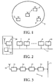
- the network nodes 1 to 4 each exchange data over radio links out.
- Network nodes 2 to 4 become normal network nodes called.
- a network node 1 to 4 contains a radio device, each of which has radio connections other network nodes, and an internal or external user interface, via the user data are delivered or read. If an internal user interface is present, the user data of electrical circuit elements in the network node generated. Such an electrical circuit element is, for example, one in the network node included video codec, which as a user via the internal user interface Exchanges data with the radio. If there is an external user interface, the user data is transferred to or from others via this user interface electrical devices.
- a user can e.g. an electrical circuit element, an electrical device, one on one or more electrical circuit elements and / or program package to be executed for one or more electrical devices, etc. his.
- a user lies outside the radio device and uses the radio device, to exchange user data with other users.
- FIG. 2 shows an example of an external user interface in the form of a bus system 11, via which several electrical devices 7 to 10 useful, control and bus synchronization data exchange with a radio device 6 of a network node 34.
- electrical device 7 to 10 can be a video recorder, a monitor, a tuner CD player etc.
- network nodes contain 1 to 4 each have a local user clock supply 35 (cf. FIG. 2).
- This local user clock supply 35 is for the entire time and frequency synchronization of the electrical Circuit components and devices 7 to 10 are required and are thus used for supply of the applications in the respective network nodes 1 to 4 with a clock which follows is referred to as the user clock.
- a radio device 6 also contains a radio clock supply (not shown in more detail) Generation of a radio clock that is independent of the user clock.
- a radio clock supply (not shown in more detail) Generation of a radio clock that is independent of the user clock.
- a wireless Network is usually a radio clock supply of a network node to the radio clock of the central network node 1 synchronized. On the synchronization of a radio clock supply will not be discussed in more detail below. It is assumed that frequency synchronization the radio clock supply has taken place.
- a local user clock supply in a network node is based on a local user clock supply of a specific network node referred to as the user master network node to synchronize.
- This user master network node its user cycle is also referred to as the master user clock, for example, the network node 2.
- the central network node does not have the function of the user master network node on, i.e. User master and central network nodes are two different network nodes. This separation makes sense because the central network node mainly for radio synchronization and not for the synchronization of the respective user cycle generating local user clock supply is responsible. But it is it cannot be ruled out that the central network node in certain cases also the user master network node is.
- radio synchronization symbol can, for example, consist of a sequence of consist of several bits.
- a radio synchronization symbol can, for example, consist of a sequence of consist of several bits.
- the Anendermaster network node 2 usually sends asynchronously to the radio synchronization gauges Time data that provide information about the master user clock. This Time data are initially received as normal user data from the central network node 1 and then distributed to all other network nodes 2 to 4. The distribution of the time data the user master network node 2 is carried out by the central network node 1, because in general it cannot be assumed that the user grid network node 2 can reach all other network nodes 3 and 4 directly, but only the central one Network node 1.
- a precise synchronization of a local user clock supply of a network node 1, 3 and 4 with the local user clock supply of the user master network node 2 can, however, only be made on the condition that it will be described later
- Switching elements generate time values (e.g. from a counter) of network nodes 1 to 4 can be generated at the same time. Only then can the time values be compared of the user master network node 2 with the time values of the central network node 1 and of normal network nodes 3 or 4 lead to evaluable results.
- Network nodes 1 to 4 are the radio synchronization characters, for example by means of a Filters (e.g. matched filters) evaluated. Such a matched filter delivers a radio synchronization pulse, its maximum value for determining the on the respective local user clock related time values is used.
- the method to be shown below for frequency synchronization of the local user clock supplies only requires that all network nodes 2 to 4 have the radio synchronization characters can receive from central network node 1 and that the network node 1, 3 and 4 the time data related to the master user cycle from the user master network node 2 can receive.
- PLL phase locked loop
- the central one Network node 1 receives this time data directly from the user master network node 2, and the normal network nodes 3 and 4 receive the time data indirectly from the user master network node 2 via the central network node 1.
- the radio devices 6 in the Network nodes 1 to 4 enable the transmission of the radio synchronization characters from central network node 1 and the transmission, distribution and processing of time data of the user master network node 2.
- FIG. 3 An exemplary embodiment of a radio device 6 is shown in FIG. 3.
- An external interface circuit 12 of the radio device 6 is connected to the bus system 11 and receives provides the user data for the radio device 6 from the bus system 11 and this if necessary after a format adaptation to a protocol device 13 of the Radio device 6.
- the interface circuit 12 leads from the protocol device 13 supplied user data for the bus system 11.
- the radio device 6 also contains a modem 14, a high-frequency circuit 15 and an antenna 16. From the antenna 16 High-frequency circuit 15 sends received data via modem 14 to the protocol device 13.
- the antenna 16 radiates from the protocol device 13 and data forwarded by the modem 14 and the radio frequency circuit 15 out.
- the protocol device 13 which is designed, for example, as a processor system, forms from the data packet units supplied by the interface circuit 12 or from the Packet units supplied by the modem 14 can be processed for the interface circuit 12 Data. In addition to the data received, a packet unit contains additional data from the Protocol device 13 formed control information.
- LLC Logical Link Control
- MAC Medium Access Control
- the MAC layer controls multiple access of a radio device 6 to the radio transmission medium and the LLC layer carries out one Flow and error control through.
- TDMA Time Division Multiplex Access
- FDMA Frequency Division Multiplex Access
- CDMA Code Division Multiplex Access
- the methods can also be combined become.
- Data is transmitted in certain assigned channels. Is a channel by a frequency range, a time range and e.g. in the CDMA process determines a spreading code
- the normal network nodes 2 to 4 are in the wireless network from the central Network node 1 controlled.
- the user master network node 2 is therefore one of the normal ones Network node, since it is not responsible for the radio synchronization of the network.
- the user master network node 2 controls the synchronization for the real-time applications that are distributed over the wireless network.
- Each network node 1 to 4 contains a user time counter that is different from the local one User clock supply receives clock pulses.
- the user time counter is in each network node 1 to 4 the local user clock supply to the frequency and, if necessary the absolute time of the user clock supply of the user master network node 2 synchronize.
- the values, which are called time values, of the respective User time counter of network nodes 1 to 4 for certain, all network nodes 1 read up to 4 known events and then compare them. The Comparison can take place asynchronously, i.e. the comparison does not have to be immediate to a particular one Time after the event. The occurrence becomes an event a predetermined criterion of a received radio signal.
- At least a frame-synchronized signal is still used in the MAC layer. That frame has different time slots for radio synchronization, control and user data and is called the MAC frame.
- the central network node 1 transmits during a predetermined Period of the MAC frame (for example at the beginning of each MAC frame) from the other network nodes 2 to 4 radio synchro to be clearly detected. ampersand.
- the radio synchronization symbol is, for example, every q MAC frame (q ⁇ 1, q ⁇ N) sent from the central network node 1.
- the successive MAC frames can have a fixed or different length.
- a MAC frame may have a certain predetermined maximum Do not exceed length, which depends on the quality of the PLL circuit tolerable maximum deviation of the local user clock supplies.
- the value q should also be selected so that the synchronization of the user clock supplies is guaranteed with the master user cycle.
- a first register stores a first time value R1 (N i ), which corresponds to the time of reception of the penultimate radio synchronization character related to the user clock
- the second register stores a time value R2 (N i ), which corresponds to the time of reception of the last radio synchronization character related to the user clock. It must be ensured here that the first time value R1 (N i ) and the second time value R2 (N i ) are read out from the user time counter after a constant delay time ⁇ after the maximum value of the radio synchronization pulse formed from the radio synchronization symbol is present.
- R1 (N i ) or R2 (N i ) are read out of the respective registers by all network nodes 1 to 4 at times which are shifted by a constant delay time.
- the maximum value is detected, for example, by a detection circuit downstream of the matched filter.
- the synchronization of the local user clock supplies in the wireless network is carried out in the following way.
- a network node 2, 3 and 4 After receiving a radio synchronization symbol from the central network node 1, a network node 2, 3 and 4 stores the time at which the radio synchronization symbol was received in relation to the user clock in its respective second register as time R2 (N i ). This time is written into the second register as a counter value from your respective user time counter.
- the content or time of the second register R2 (N i ) has been shifted to the first register and is referred to as time R1 (N i ).
- the network node 1 can also calculate the related to its user clock time, R2 (N i), as it knows the time interval between the start of a radio synchronization character and the maximum value of this radio synchronization pulse formed from the radio synchronization mark by means of the matched filter.
- FIG. 4 shows two blocks 36 and 37.
- the first block 36 relates to a radio device 6 in a network node 1 to 4 and the second block 37 to the evaluation of the counter values of a user time counter.
- Block 36 contains two blocks 38 and 39.
- Block 38 which specifies the function of the radio clock supply, supplies the radio clock FT and block 39 evaluates the radio synchronization signal received via the radio path.
- the maximum value of the radio synchronization pulse formed from the radio synchronization symbol is supplied to block 37 at the time of reception of the radio synchronization symbol.
- Block 37 contains five further blocks 40 to 44.
- Block 40 represents the user clock supply and supplies a user clock to block 41.
- Block 41 is a user time counter that increments its counter value with each user clock.
- Block 42 reads out a counter value from the user time counter (block 41) when block 39 supplies an enable pulse triggered by an incoming radio synchronization symbol.
- the enable pulse is formed by a detection circuit when the maximum value of the radio synchronization pulse from the matched filter has been reached.
- the read counter value is written by the block 42 into the second register as counter value R2 (N i ).
- the block previously wrote the old counter value as counter value R1 (N i ) into the first register.
- Processing the different signals in blocks 36 and 37 results in a network node-specific delay ⁇ between the readout time of the user counter and the reception time of the maximum value of the radio synchronization pulse. This time delay is symbolized by block 44, which is arranged between blocks 39 and 42.
- the time interval between the start of the radio synchronization pulse resulting from the radio synchronization symbol and the maximum value of the radio synchronization pulse is taken into account because the central network node 1 can generally not transmit and receive at the same time.
- a specific time slot of the MAC frame can be used for the transmission of the difference result ⁇ 2 .
- the central network node 1 sends out the difference value ⁇ 2 as time data during the MAC frame.
- the time data are sent out over radio distribution connections during a specific time slot of this MAC frame, ie this time data is determined for each normal network node 2 to 4.
- Each normal network node 3 and 4 except for the user master network node, after receiving the difference value ⁇ 2 and after forming a difference between the times R1 (N i ) and R2 (N i ) stored in the respective own registers, compares the received ones with i 3 or 4 Difference value ⁇ 2 with the calculated difference value ⁇ 3 or ⁇ 4 .
- FIG. 5 shows a MAC frame.
- the corrected time value R2 '(N 2 ) is required for the later calculation of the absolute time in the wireless network.
- the transmission process of the user master network node 2 is identified by AM-S and the reception process of the central network node 1 by CC-R.
- the time data received from the central network node 1 are distributed to the other normal network nodes 3 and 4 during a subsequent time slot p (p> k, p ⁇ N) of the MAC frame.
- This transmission process of the central network node 1 during the MAC frame m is referred to as CC-S and the reception process of the normal network nodes 3 and 4 with NN-R.
- the user time counter and the first and second registers can be discrete components and for example be part of a separate circuit, which is also another switching element for difference formation and comparison with other difference values. Advantageous but it is to fall back on existing switching elements.
- the interface circuit 12 in each radio device 6, which is designed, for example, as a processor system is the functions of the user time counter, the first and second register and the Take over calculation functions. After calculating the difference value, the Interface circuit 12 then optionally a frequency correction value to the associated user clock supply.
- the matched filter and the detection circuit can, for example Be part of the modem 14. 4, the function of the user time counter, of the first and second register and the calculation function part of the Blocks 37. The function of the matched filter and the detection circuit is part of the Blocks 36.
- the local user clock supplies can also be synchronized by averaging several time values in order to reduce the effects of fluctuations in the transmission of the time data.
- the following formula must be calculated in a network node 1 to 4:
- ⁇ 2 is the sum of the difference values of the user master network node 2
- ⁇ i, j is a difference value of a network node i at the time j and ⁇ 2, j Difference value of the user master network node 2 at the time j.
- the index n is the index for the last difference value ⁇ i, n or ⁇ 2, n formed .
- This averaging makes the synchronization insensitive to disturbances in the transmission of the time data and to a jitter effect during the reading process from the respective user time counter.
- the interface circuit 12 can also contain additional registers or memories in each radio device 6 for this averaging.
- a difference value ⁇ 2 instead of transmitting a difference value ⁇ 2 as time data, only the time value R2 (N 2 ) of the user master network node can also be transmitted.
- the central network. Node 1 and the normal network nodes 3 and 4 then calculate the difference value ⁇ 2 from the two last received time values R2 (N 2 ) instead of the user master network node 2.
- additional registers can be contained in the interface circuit 12 in each radio device 6 for this difference formation.
- the synchronization of a user clock supply of a normal network node can also be carried out when the normal network node does not directly transfer data from that central network node can receive.
- This situation is shown in Fig. 6.
- the network nodes 18 to 21 Exchange data via radio links. 6
- the network node 18 is the central network node
- the network node 19 is the user master network node (and at the same time also a normal network node)
- network nodes 20 and 21 are normal network nodes.
- Outside the ellipse 17 there is another normal network node 22 which has no data can receive from the central network node 18.
- the entire wireless network is represented by an ellipse 23 drawn with a solid line in FIG. 6.
- the normal network node 22 is also referred to as a hidden network node, because it has no data from the central network node 18 but data over a radio link can receive from the normal network node 21.
- the normal network node 21 will also referred to as an intermediate network node because of this data from the central network node 18 can be transmitted to the hidden network node 22.
- the synchronization of the local user clock supply of the hidden network node 22 the user clock of the user master mink node 19 is in the following manner carried out. If the user clock of the intermediate network node 21 with the master user clock the user master network node 19 according to the scheme described above is synchronized, the intermediate network node generates similar radio synchronization characters (special radio synchronization signs) like the central network node 1. Such a special one Radio synchronization characters can also consist of a sequence of several bits, which are transmitted during a predetermined time slot of the MAC frame. This special synchronization character is, for example, every q MAC frame (q ⁇ 1, q ⁇ N) sent from the intermediate network node 21. The value q should be chosen that the synchronization of the user clock supply of the hidden network node 22 with the help of a PLL circuit with the master user clock is guaranteed.
- the time interval between the start of a special radio synchronization symbol and the maximum value of the special radio synchronization pulse resulting from the special radio synchronization symbol is taken into account because the intermediate network node 21 cannot generally send and receive at the same time.
- the intermediate network node 21 sends the time data ⁇ 21 at a later time than the radio synchronization symbol. This point in time can lie, for example, between the transmission times of two special radio synchronization characters.
- the hidden network node 22 After receiving the time data ⁇ 21 , the hidden network node 22 compares the difference values ⁇ 21 and ⁇ 22 . If ⁇ 21 > ⁇ 22 , the local user clock supply of the hidden network node 22 must be around the value ( ⁇ 21 - ⁇ 22 ) / ⁇ 21 increase.
- the local user clock supply must be adjusted by the value ( ⁇ 22 - ⁇ 21 ) / ⁇ 21 reduced If the two difference values ⁇ 21 and ⁇ 22 are identical, the local user clock supply of the hidden network node 22 is synchronized with the user clock of the intermediate network node 21 and thus indirectly with the master user clock of the user master network node 19.
- Averaging can also be carried out for a hidden network node using the following formula:
- ⁇ 21 is the sum of the difference values of the network node 21, ⁇ 22 the sum of the difference values of the network node 22, ⁇ 21, j is a difference value of the network node 21 at the time j and ⁇ 22, j is a difference value of the network node 22 at the time j.
- N specifies the number of difference values that are taken into account for averaging.
- the network nodes of the Sub-network which does not contain the user master network node, with the help of a Bridge network node that uses the network nodes of the subnetworks to transmit data over radio links can synchronize with the master user clock.
- a wireless one Network with two sub-networks that are connected to one another via a bridge node 24 7 shows.
- the first sub-network contains, in addition to the bridge network node 24 the central network node 25, the user master network node 26 and the normal nodes 27 and 28.
- the area in which the central node 25 data can exchange with the other network nodes 24, 26, 27 and 28 is by an ellipse 29 indicated in FIG. 7.
- the second sub-network in Fig. 7 also contains that Bridge network node 24 has a central network node 30 and two normal network nodes 31 and 32.
- the ellipse 33 shown in FIG. 7 indicates the area in which a data exchange of the central network node 30 is possible with other network nodes.
- the bridge network node 24, which at the central network nodes 25 and 30 of the two Sub-networks registered contains a radio device with either one or two Radio branches.
- a radio branch consists of the switching elements shown in FIG. 3. If the radio device of the bridge network node contains two radio branches, there is one permanent connection with both sub-networks 29 and 33. In the other case with one Radio branch in the radio device of the bridge network node 24 is either one Connection to the first or the second sub-network.
- the connection time of the Bridge network node 24 with the sub-networks can each be the same or different his.
- the use of a radio device with a radio branch in the bridge network node 24 has the advantage of less circuitry.
- the user clock supply of the bridge network node is already synchronized with the master user clock using the method described above.
- the bridge network node 24 then simulates for the second sub-network with the central network node 30 the network node which supplies the master user clock.
- the user clock supply of the central network node 30 is synchronized with the user clock of the bridge network node 24.
- the Connection time to a sub-network does not exceed a certain period of time, thus ensuring good synchronization accuracy for the other sub-network is.
- the method for time and frequency synchronization described for two sub-networks of the user clock supplies in a sub-network that is not the user master network node contains, can also be extended to others in the wireless network contained sub-networks.
- These sub-networks, each from a central one Network nodes are controlled, obtained from a bridge network node other subnetwork the necessary data. This allows the other sub-networks according to the scheme described above, the time data of the user master network node successively receive.
- Averaging can also be carried out for the network nodes 30 to 32 of the second sub-network.
- N specifies the number of difference values that are taken into account for averaging.
- This value R2 '(N 2 ) is distributed by the central network node 1 to the normal network nodes 3 and 4.
- the synchronization, for example in a normal network node 3 or 4, to the absolute time of the user master network node 2 must take place after the frequency synchronization of the assigned user clock supply to the user clock supply of the user master network node 2.
- a synchronization of a hidden network node using the frequency and time-synchronized intermediate network node (see FIG. 6) and a network node in a second sub-network using a bridge network node (see FIG. 7) to the absolute time of the user master Network node 2 is possible in the same way after the frequency synchronization of the respective network node to the absolute time.
- the absolute Time the propagation delay between the network nodes are taken into account. This can be done, for example, by measuring the transit time of test signals between the Network nodes are determined.
Landscapes
- Engineering & Computer Science (AREA)
- Textile Engineering (AREA)
- Computer Networks & Wireless Communication (AREA)
- Signal Processing (AREA)
- Mobile Radio Communication Systems (AREA)
- Synchronisation In Digital Transmission Systems (AREA)
- Small-Scale Networks (AREA)
- Data Exchanges In Wide-Area Networks (AREA)
Applications Claiming Priority (2)
| Application Number | Priority Date | Filing Date | Title |
|---|---|---|---|
| DE19912556 | 1999-03-19 | ||
| DE19912556A DE19912556A1 (de) | 1999-03-19 | 1999-03-19 | Drahtloses Netzwerk mit einer Anwendertaktsynchronisation |
Publications (1)
| Publication Number | Publication Date |
|---|---|
| EP1039660A2 true EP1039660A2 (fr) | 2000-09-27 |
Family
ID=7901736
Family Applications (1)
| Application Number | Title | Priority Date | Filing Date |
|---|---|---|---|
| EP00200851A Withdrawn EP1039660A2 (fr) | 1999-03-19 | 2000-03-10 | Réseau sans fils avec synchronisation d'utilisateur |
Country Status (7)
| Country | Link |
|---|---|
| US (1) | US6714611B1 (fr) |
| EP (1) | EP1039660A2 (fr) |
| JP (1) | JP2000307559A (fr) |
| KR (1) | KR100655625B1 (fr) |
| CN (1) | CN1199493C (fr) |
| DE (1) | DE19912556A1 (fr) |
| TW (1) | TW484291B (fr) |
Families Citing this family (18)
| Publication number | Priority date | Publication date | Assignee | Title |
|---|---|---|---|---|
| DE60041470D1 (de) * | 1999-05-11 | 2009-03-19 | Canon Kk | Verfahren und Vorrichtung zur Synchronisierung zwischen zwei Netzwerken |
| EP1211824B1 (fr) | 2000-12-01 | 2008-08-06 | Siemens Enterprise Communications GmbH & Co. KG | Procédé de synchronisation de diverses stations de base d'un réseau radio mobile couplées à des commutateurs |
| DE10065117A1 (de) * | 2000-12-28 | 2002-07-04 | Bosch Gmbh Robert | Verfahren und Kommunikationssystem zum Austausch von Daten zwischen mindestens zwei Teilnehmern über ein Bussystem |
| US7036013B2 (en) * | 2002-01-31 | 2006-04-25 | Brocade Communications Systems, Inc. | Secure distributed time service in the fabric environment |
| US7356618B2 (en) * | 2003-12-31 | 2008-04-08 | Intel Corporation | Method and system for synchronizing platform clocks in a distributed wireless platform |
| US7266713B2 (en) * | 2004-01-09 | 2007-09-04 | Intel Corporation | Apparatus and method for adaptation of time synchronization of a plurality of multimedia streams |
| JP4254708B2 (ja) * | 2004-12-27 | 2009-04-15 | 沖電気工業株式会社 | 通信タイミング制御装置、通信タイミング制御方法、ノード及び通信システム |
| WO2006097880A1 (fr) * | 2005-03-18 | 2006-09-21 | Philips Intellectual Property & Standards Gmbh | Procede de synchronisation de noeuds de reseau |
| AU2007307684A1 (en) * | 2006-10-11 | 2008-04-17 | Quartex, Division Of Primex, Inc. | Traceable record generation system and method using wireless networks |
| JP4810520B2 (ja) * | 2007-09-21 | 2011-11-09 | 日本電信電話株式会社 | クライアント装置および同期システム |
| EP2556621A4 (fr) * | 2010-04-08 | 2016-08-31 | Freescale Semiconductor Inc | Système renifleur multi-canal et procédé pour synchronisation de renifleur multi-canal |
| FR2994000B1 (fr) | 2012-07-30 | 2015-06-05 | Airbus Operations Sas | Procede de surveillance de l'execution coordonnee de taches sequencees par une carte electronique comportant au moins deux processeurs synchronises sur une meme horloge |
| FR2994001B1 (fr) * | 2012-07-30 | 2015-05-29 | Airbus Operations Sas | Procede de surveillance de l'execution coordonnee de taches sequencees par une carte electronique comportant au moins deux processeurs synchronises sur deux horloges differentes |
| US9458711B2 (en) | 2012-11-30 | 2016-10-04 | XACT Downhole Telemerty, Inc. | Downhole low rate linear repeater relay network timing system and method |
| CA2906215C (fr) | 2013-03-15 | 2021-01-19 | Xact Downhole Telemetry Inc. | Systeme et procede de reseau robuste de repeteurs de telemetrie |
| US9891966B2 (en) | 2015-02-10 | 2018-02-13 | Red Hat, Inc. | Idempotent mode of executing commands triggered by complex event processing |
| US10423468B2 (en) * | 2015-02-10 | 2019-09-24 | Red Hat, Inc. | Complex event processing using pseudo-clock |
| DE102021116893A1 (de) | 2021-06-30 | 2023-01-05 | Sennheiser Electronic Gmbh & Co. Kg | Verfahren und Vorrichtung zur drahtlosen Synchronisation von Mobilgeräten |
Family Cites Families (3)
| Publication number | Priority date | Publication date | Assignee | Title |
|---|---|---|---|---|
| DE19630398C1 (de) * | 1996-07-26 | 1998-02-12 | Siemens Ag | Verfahren zum Synchronisieren eines in einer Datenempfangsstation zu generierenden Taktsignals mit einem in einer Datensendestation verwendeten Taktsignal |
| US6308280B1 (en) * | 1998-06-25 | 2001-10-23 | Hughes Electronics Corporation | System for synchronizing discrete components to a common clock source |
| US6278710B1 (en) * | 1998-09-10 | 2001-08-21 | Agilent Technologies, Inc. | Enhancements to time synchronization in distributed systems |
-
1999
- 1999-03-19 DE DE19912556A patent/DE19912556A1/de not_active Withdrawn
-
2000
- 2000-03-10 JP JP2000066112A patent/JP2000307559A/ja active Pending
- 2000-03-10 EP EP00200851A patent/EP1039660A2/fr not_active Withdrawn
- 2000-03-15 CN CNB001041606A patent/CN1199493C/zh not_active Expired - Fee Related
- 2000-03-17 US US09/527,278 patent/US6714611B1/en not_active Expired - Fee Related
- 2000-03-20 KR KR1020000013976A patent/KR100655625B1/ko not_active Expired - Fee Related
- 2000-04-27 TW TW089108008A patent/TW484291B/zh not_active IP Right Cessation
Also Published As
| Publication number | Publication date |
|---|---|
| DE19912556A1 (de) | 2000-09-21 |
| US6714611B1 (en) | 2004-03-30 |
| CN1270483A (zh) | 2000-10-18 |
| JP2000307559A (ja) | 2000-11-02 |
| KR20000076918A (ko) | 2000-12-26 |
| KR100655625B1 (ko) | 2006-12-12 |
| TW484291B (en) | 2002-04-21 |
| CN1199493C (zh) | 2005-04-27 |
Similar Documents
| Publication | Publication Date | Title |
|---|---|---|
| EP1039660A2 (fr) | Réseau sans fils avec synchronisation d'utilisateur | |
| EP0570557B1 (fr) | Procede de generation d'une base de temps commune dans un systeme a unites informatiques decentralisees | |
| EP0503732B1 (fr) | Méthode et système de transmission pour la hiérarchie numérique synchrone | |
| DE60216647T2 (de) | Verfahren und System zur Erzeugung einer Zeitdifferenz hinsichtlich des Minizeitschlitz-Taktes und -Zählers in Headendvorrichgtungen | |
| DE69931218T2 (de) | Verfahren zur synchronisierung von netzwerkknoten | |
| DE60103758T2 (de) | Master/slave-synchronisierungsverfahren in einem bluetooth-system | |
| DE69533579T2 (de) | Synchronisierung in einem Datenkommunikationsnetzwerk | |
| DE102021205793A1 (de) | Genauigkeit des zeitstempels auf der empfangsseite | |
| DE69124319T2 (de) | Bitsynchronisierung mittels elastisches Speichers | |
| DE60220592T2 (de) | Taktsynchronisation durch Teilnetzwerke | |
| DE60207897T2 (de) | Synchrones datenübertragungsystem für zeitempfindliche daten in einem paketvermittelten netzwerk | |
| DE60013950T2 (de) | Netzwerk-Synchronisiersystem und Netzwerk-Synchronisierverfahren | |
| DE4110933A1 (de) | Uebertragungssystem fuer die synchrone digitale hierachie | |
| EP0849904B1 (fr) | Système de transmission digitale synchrone, unité de régulation, élément de réseau et générateur d'horloge central | |
| DE602005005816T2 (de) | Verfahren und system zur verteilten synchronisation | |
| AT523930B1 (de) | Zeitsynchronisation in einem Echtzeit-Netzwerk | |
| WO2012038493A1 (fr) | Dispositif et procédé de mise à disposition d'une information de temps globale dans une communication par bus commandée par des événements | |
| EP1198911B1 (fr) | Procede et systeme de synchronisation pour sources de signal d'horloge, en particulier dans des systemes de communication a transmission par paquets | |
| EP1639758B1 (fr) | Procede et dispositif pour l'echange de donnees par l'intermediaire d'un systeme de bus | |
| DE69938098T2 (de) | Verfahren und System zur Übertragung von Daten auf einem seriellen Bus | |
| DE602004005991T2 (de) | Verfahren zur taktsynchronisation drahtloser 1394-busse für über ieee 802.11-lan netzwerk verbundene knoten | |
| EP0530749A1 (fr) | Méthode et dispositif pour la synchronisation d'un générateur d'horloge d'un système de commutation de communication | |
| DE10191695B4 (de) | Verfahren und Kommunikationskontrolleinheit zur Multimaster Uhrensynchronisation in einem verteilten Echtzeitcomputersystem | |
| DE60301873T2 (de) | Internes zeichengabeverfahren zur unterstützung der taktsynchronisation von über ein drahtloses lokales netzwerk verbundenen knoten | |
| DE4105267A1 (de) | Verbesserte synchronisationstechnik |
Legal Events
| Date | Code | Title | Description |
|---|---|---|---|
| PUAI | Public reference made under article 153(3) epc to a published international application that has entered the european phase |
Free format text: ORIGINAL CODE: 0009012 |
|
| AK | Designated contracting states |
Kind code of ref document: A2 Designated state(s): AT BE CH CY DE DK ES FI FR GB GR IE IT LI LU MC NL PT SE |
|
| AX | Request for extension of the european patent |
Free format text: AL;LT;LV;MK;RO;SI |
|
| RAP1 | Party data changed (applicant data changed or rights of an application transferred) |
Owner name: PHILIPS CORPORATE INTELLECTUAL PROPERTY GMBH Owner name: KONINKLIJKE PHILIPS ELECTRONICS N.V. |
|
| RAP1 | Party data changed (applicant data changed or rights of an application transferred) |
Owner name: KONINKLIJKE PHILIPS ELECTRONICS N.V. Owner name: PHILIPS INTELLECTUAL PROPERTY & STANDARDS GMBH |
|
| STAA | Information on the status of an ep patent application or granted ep patent |
Free format text: STATUS: THE APPLICATION IS DEEMED TO BE WITHDRAWN |
|
| 18D | Application deemed to be withdrawn |
Effective date: 20081001 |