EP1040932A1 - Wiederverwertbare Farbbandkassette - Google Patents
Wiederverwertbare Farbbandkassette Download PDFInfo
- Publication number
- EP1040932A1 EP1040932A1 EP00302500A EP00302500A EP1040932A1 EP 1040932 A1 EP1040932 A1 EP 1040932A1 EP 00302500 A EP00302500 A EP 00302500A EP 00302500 A EP00302500 A EP 00302500A EP 1040932 A1 EP1040932 A1 EP 1040932A1
- Authority
- EP
- European Patent Office
- Prior art keywords
- ink ribbon
- case
- reel
- lower case
- section
- Prior art date
- Legal status (The legal status is an assumption and is not a legal conclusion. Google has not performed a legal analysis and makes no representation as to the accuracy of the status listed.)
- Granted
Links
- 239000000853 adhesive Substances 0.000 description 6
- 238000000034 method Methods 0.000 description 5
- 239000000463 material Substances 0.000 description 2
- 238000004804 winding Methods 0.000 description 2
- 241000283070 Equus zebra Species 0.000 description 1
- 239000002390 adhesive tape Substances 0.000 description 1
- 230000007613 environmental effect Effects 0.000 description 1
- 230000001788 irregular Effects 0.000 description 1
- 238000012423 maintenance Methods 0.000 description 1
- 238000002844 melting Methods 0.000 description 1
- 230000008018 melting Effects 0.000 description 1
- 239000002985 plastic film Substances 0.000 description 1
- 229920006255 plastic film Polymers 0.000 description 1
- 239000000758 substrate Substances 0.000 description 1
- 229920003002 synthetic resin Polymers 0.000 description 1
- 239000000057 synthetic resin Substances 0.000 description 1
Images

Classifications
-
- B—PERFORMING OPERATIONS; TRANSPORTING
- B41—PRINTING; LINING MACHINES; TYPEWRITERS; STAMPS
- B41J—TYPEWRITERS; SELECTIVE PRINTING MECHANISMS, i.e. MECHANISMS PRINTING OTHERWISE THAN FROM A FORME; CORRECTION OF TYPOGRAPHICAL ERRORS
- B41J35/00—Other apparatus or arrangements associated with, or incorporated in, ink-ribbon mechanisms
- B41J35/28—Detachable carriers or holders for ink-ribbon mechanisms
-
- B—PERFORMING OPERATIONS; TRANSPORTING
- B41—PRINTING; LINING MACHINES; TYPEWRITERS; STAMPS
- B41J—TYPEWRITERS; SELECTIVE PRINTING MECHANISMS, i.e. MECHANISMS PRINTING OTHERWISE THAN FROM A FORME; CORRECTION OF TYPOGRAPHICAL ERRORS
- B41J32/00—Ink-ribbon cartridges
Definitions
- This invention relates to an ink ribbon cassette, and more particularly an ink ribbon cassette in which an ink ribbon already used can be replaced with an ink ribbon not yet used.
- a thermal transfer printer in the prior art in which a plurality of heat generating elements are selectively driven in response to a recording signal while a thermal head is being moved along a platen, ink of an ink ribbon is melted and transferred to a recording paper to perform a desired recording has been widely utilized as an output device for a computer, a word processor and the like due to its easiness in maintenance, low noise or a high quality printing and the like.
- the prior art ink ribbon cassette 1 used in such a thermal transfer printer as above is made such that a long ink ribbon 3 having an ink layer coated on its surface is stored in a space within a lower case 2a and an upper case (not shown) constituting the main body case 2 as shown in Fig. 7.
- both ends of the ink ribbon 3 are rotatably pivoted to the lower case 2a and the upper case.
- a ribbon drawing path 7 having a plurality of guide members 6 arranged therein to draw the ink ribbon 3, and then the zig-zag formed ink ribbon 3 is drawn in the ribbon drawing path 7.
- the ribbon drawing path 7 is formed with a concave-shaped ribbon drawing section 8 for once drawing the ink ribbon 3 out of the main body case 2.
- a recording head of a thermal transfer printer (not shown) and then ink of the ink ribbon 3 is transferred to the recording paper through moving-up or moving-down of the recording head.
- the ink ribbon cassette 1 having such a configuration as above is made such that the lower case 2a and the upper case (not shown) are fixed to each other by melting and the like and they are integrally assembled.
- the ink ribbon cassette of the present invention is comprised of an ink ribbon; a main body case composed of an upper case and a lower case for storing the ink ribbon therein; a take-up reel and a supply reel having the ink ribbon wound therearound, rotatably pivoted and supported at the upper case and the lower case; a ribbon drawing section where the ink ribbon is once drawn between the take-up reel and the supply reel from the main body case to an external side, wherein the upper case can be divided into a first case positioned at the ribbon drawing side and a second case having shaft bearing sections capable of pivotally supporting the take-up reel and the supply reel, and the second case is removably attached to the lower case.
- the second case is removably attached to the lower case through a snap fitting.
- the ink ribbon already used can be replaced with an ink ribbon not yet used under a state in which the second case is being removed from the lower case.
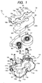
- Fig. 1 is an exploded perspective view for showing the ink ribbon cassette of the present invention
- Fig. 2 is an enlarged view for showing a substantial part of the ink ribbon of the present invention
- Fig. 3 is a perspective view for showing a second case of the present invention
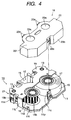
- Fig. 4 is an exploded perspective view for illustrating an assembling method of the present invention
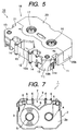
- Fig. 5 is a perspective view for showing an ink ribbon cassette of the present invention
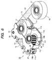
- Fig. 6 is an illustrative view for showing a method for replacing an ink ribbon already used with an ink ribbon not yet used.
- an ink ribbon cassette 10 of the present invention is constructed such that a main body case 21 having an inner hollow cavity and whose outer shell is comprised of a lower case 11 and an upper case 18 is made of material such as synthetic resin and the like and arranged.
- the lower case 11 is made such that a pair of shaft bearing sections 11a comprised of holes are formed at a substantial central section of a bottom plate 11p, wherein a first engaging section 11c protruded upwardly is formed at the central section of the side section 11b of the rear side of each of the shaft bearing sections 11a and hook-like second engaging sections 11f, 11f are formed inside both right and left sides 11e and 11d.
- a first side wall 11g having a predetermined height is protruded and formed at a front side of the bearing section 11a, and second side walls 11j, 11j at predetermined clearances 11h, 11h are formed outside the section where both right and left ends of the first side wall 11g are opposed to each other and the second side wall 11j, 11j are formed at the same height as that of the first side wall 11g.
- Each of the second side walls 11j, 11j is extended to form from the front side of the lower case 11 to a location near the central section of each of the right and left side sections 11e, 11d, respectively.
- the lower case 11 is formed with an ink ribbon drawing path 12 where the ink ribbon 15 to be described later is being zig-zag formed and drawn near a location including two clearances 11h, 11h at the front side of the bearing sections 11a, 11a.
- This ink ribbon drawing path 12 is set such that a pair of rollers 13, 13 are rotatably pivoted in the holes 11k, 11k of the lower case 11 and each of a plurality of pin rollers 14 is rotatably pivoted at each of a plurality of pins 11m of the lower case 11.
- each of the second side walls 11j extended and formed at the right and left side sections 11e, 11d has third engaging sections 11n comprised of a pair of rectangular holes which are formed at locations opposite to each other, fixing legs 19b of the first case 19 of the upper case 18 to be described later are snap engaged with the third engaging sections 11n so as to cause the first case 19 to be fixed to the lower case 11.
- the ribbon drawing path 12 is formed with a concave-shaped ribbon drawing section 12a where the ink ribbon 15 to be described later is once drawn out of the main body case 21 to an external part.
- a recording head (not shown) at a printer side is positioned at the ribbon drawing section 12a in such a manner that the head can be moved up and down.
- An ink ribbon 15 coated with an ink layer of desired color is mounted on the surface of a substrate material comprised of a long thin film-like plastic film on the bottom plate 11p of the lower case 11 and then stored in the main body case 21.
- the ink ribbon 15 is formed with a black-colored ink section 15a shown in Fig. 2 having the ink layer coated on its front surface side and sensor sections 15b, 15c of zebra patterns at each of both ends of one side and the other side of the ink section 15a are formed outside of the ink section 15a.
- the rear surfaces at the extremity ends having the sensor sections 15b, 15c formed thereat are coated with viscous adhesive agent (not shown) not hardened, with a single surface adhesive tape.
- the extremity end of one sensor section 15b is adhered to the first reel 16 comprised of a supply reel and further the extremity end of the sensor section 15c at the other side is adhered to the second reel 17 comprised of a take-up reel, respectively, and the ink ribbon 15 is wound around the first reel 16.
- the first and second reels 16, 17 are made such that their lower ends shown in the figure are pivotally supported at shaft bearing sections 11a, 11a of the lower case 11 and their upper ends shown in the figure are pivotally supported at the shaft bearing sections 20a, 20a of the upper case to be described later and they can be rotated.
- An upper case 18 formed in the substantial same shape as that of the lower case 11 as seen in its top plan view is arranged above the ink ribbon 15 mounted at the lower case 11, and the upper case 18 is formed such that the first case 19 and the second case 20 are integerally formed and can be separated from each other.
- the first case 19 is formed such that the upper plate 19d is formed to cover the ink ribbon 15 drawn in the ribbon drawing path 12, the upper plate 19d is provided with a pair of rotatable rollers 13 and some pins (not shown) at positions opposing against a plurality of pins 11m of the lower case 11 so as to pivotally support each of the pin rollers 14.
- the first case 19 is formed with a concave-shaped ribbon drawing section 19a of the same shape as that described above at the section where the concave-shaped ribbon drawing section 12a of the lower case 11 is positioned. Further, the first case 19 is made such that a pair of fixing legs 19b are projected and formed from both right and left sides in a downward direction, the pair of fixing legs 19b are snap fitted to the third engaging sections 11n of the lower case 11, the first case 19 is fixed to the lower case 11, thereafter the first case 19 is press fitted with pins into the holes formed in the first side wall 11g or the second side wall 11j of the lower case 11 and fixed there.
- the second case 20 forming the upper case 18 together with the first case 19 is formed with a pair of shaft bearing sections 20a, 20a comprised of shaft holes for rotatably pivoting the first reel 16 and the second reel 17 on the upper plate 20f placed at positions opposite to the shaft bearing sections 11a, 11a of the lower case 11.
- an outer circumferential section of the second case 20 is formed with a side wall 20b having a predetermined height for shielding an inner section of the main body case 21 and further a central inner section of a rearward segment of the side wall 20b is formed with a first engaging section 20c having a mountain-shaped extremity end.
- This first engaging section 20c can be snap fitted with the first engaging section 11c of the lower case 11, the first engaging section 20c of the second case 20 is snap fitted with the first engaging section 11c of the lower case 11 to enable the second case 20 to be removably fixed to the lower case 11.
- the right and left side walls 20b of the second case 20 are formed with hook-like second engaging sections 20d at their lower sides, the second engaging sections 20d are snap fitted with the second engaging sections 11f of the lower case 11 and even if an external pressure is applied to the side walls 20b, the side walls 20b are not deformed.
- each of fork-like third engaging sections 20e, 20e protruded outside in parallel direction in respect to the upper plate 20f is formed at an outer circumferential section of the second case 20 and near the shaft bearing sections 20a, 20a, and then the third engaging sections 20e, 20e are engaged with the engaging sections 19c of the first case 19 alternatively in a horizontal direction.
- Assembling of the ink ribbon cassette 10 of the present invention is carried out such that at first the rollers 13 are assembled in the holes 11k positioned at the ribbon drawing section 12 and at the same time the pin rollers are assembled to the pins 11m.
- the first reel 16 composed of a supply reel having ink ribbon 15 not yet used wound therearound is inserted into one shaft bearing section 11a.
- the second reel 17 kept at a state in which the ink ribbon 15 is not wound is inserted into the other shaft bearing section 11a.
- the aforesaid ink ribbon 15 not yet used is set such that the sensor section 15b at one side end section of it is adhered to the first reel 16, the ink ribbon 15 is wound around the first reel 16 and the sensor section 15c at the other end of the winding terminal side is adhered to the ink ribbon 15 not yet used wound around the first reel 16.
- the sensor section 15c at the other end adhered to the ink ribbon 15 wound around the first reel 16 is peeled off and then the sensor section 15c is drawn in the ribbon drawing path 12 and then drawn out to the second reel 17 side. Then, the ink ribbon 15 not yet used is drawn in the ribbon drawing path 12.
- the first case 19 constituting a part of the upper case 18 is applied to cover the ribbon drawing path 12 having the ink ribbon 15 drawn therearound, the fixing legs 19b of the first case 19 are engaged with the third engaging sections 11n of the lower case 11, the first case 19 is snap fitted with the lower case 11 and fixed there.
- the pins (not shown) of the first case 19 are press fitted to either the first side walls 11g or the second side walls 11j of the lower case 11 by a press fitting machine or the like (not shown) and fixed there.
- the second case 20 is applied to cover the first reel 16 and the second reel 17 pivotally supported on the lower case 11.
- the first engaging section 20c of the second case 20 is snap engaged with the first engaging section 11c of the lower case 11 and the second engaging section 20d is snap fitted with the second engaging sections 11f of the lower case 11, respectively, and concurrently the third engaging sections 20d of the second case 20 are engaged with the engaging sections 19c of the first case 19 to cause the divided first and second cases 19, 20 to be integrally assembled, and the second case 20 is removably fixed to the lower case 11 to complete an assembling of the ink ribbon cassette 10 of the present invention.
- the ink ribbon cassette 10, assembled in this order, is mounted on a carriage for a thermal transfer printer (not shown), a desired image is printed on a recording paper by a thermal head (not shown) while this carriage is being moved along a platen (not shown), the take-up reel 17 is rotated to take up the ink ribbon 15 already used.
- a method for replacing the ink ribbon 15 already used in the ink ribbon cassette 10 of the present invention as described above with an ink ribbon 15 not yet used will be described as follows.
- an item in which an ink ribbon 15' not yet used but wound like a pan-cake is prepared in advance on the second reel 17 as shown in Fig. 6.
- any one of the first reel 16 and the second reel 17 can be similarly used.
- the ink ribbon 15 stored in the ribbon cassette 10 as shown in Fig. 5 is an ink ribbon already used, wherein the second case 20 is manually pulled up to disengage the snap-engagement between the lower case 11 and the second case 20 and to remove the second case 20 from the lower case 11.
- the ink ribbon cassette 10 is set such that as shown in Fig. 4, the first reel having the adhered sensor section 15b already finished in taking-up operation and the second reel 17 having the ink ribbon 15 already used and taken up are exposed.
- the second reel 17 is manually rotated in a clockwise direction to cause all the remained portions which is not taken up of the sensor section 15b wound around the first reel 16 are taken up.
- the adhesive agent is yet adhered to the sensor section 15b' when the sensor section 15b' is peeled off from the ink ribbon 15' not yet used, so that it is not especially necessary to coat the adhesive agent to it.
- the first reel 16 is manually rotated in a counter-clockwise direction to cause the ink ribbon 15 already used and taken up on the second reel 17 to be rewound slightly on the first reel 16.
- the sensor section 15b' of the ink ribbon 15' not yet used is drawn in the ribbon drawing path 12 and then exposed at the first reel 16.
- the sensor section 15b' of the ink ribbon 15' not yet used but exposed at the first reel 16 is peeled off from the ink ribbon 15 already used.
- the second reel 17 is manually rotated in a clockwise direction and the ink ribbon 15 already used and slightly rewound on the first reel 16 is taken up again to the second reel 17.
- the sensor section 15b of the ink ribbon 15 already used is peeled off and the extremity end of the sensor section 15b' of the ink ribbon 15' not yet used is adhered to the first reel 16 having no adhesive agent thereon.
- the second reel 17 having the ink ribbon already used, wound therearound and formed like a pan-cake is pulled out of the shaft bearing section 11a of the lower case 11 and the second reel 17 having the ink ribbon 15' not yet used but wound therearound with the sensor section 15b' being already adhered to the first reel 16 is inserted into the shaft bearing section 11a.
- the second case 20 of the upper case 18 is applied to cover from above the first reel 16 and the second reel 17, snap fitted with the lower case 11 and fixed there to enable the ink ribbon already used to be replaced with the ink ribbon not yet used .
- the ink ribbon already used is replaced with the ink ribbon not yet used in this way to enable the ink ribbon already used to be easily replaced with an ink ribbon not yet used without performing any complex work for drawing the ribbon drawing section 12 for the ink ribbon 15.
- first case 19 is fixed to the lower case 11 by a pin press fitting and the like.
- first case 19 can be fixed to or removed from the lower case 11 in the same manner as that for the second case 20.
- the ink ribbon cassette can be divided into the first case where the upper case is positioned at the ribbon drawing section and the second case having the shaft bearing sections capable of pivotally supporting the take-up reel and the supply reel. Since the second case is removably fixed to the lower case, it is possible to provide an ink ribbon cassette in which the second case is fixed to or removed from the lower case and the ink ribbon already used can be easily replaced with the ink ribbon not yet used .
- the aforesaid second case is removably fixed to the aforesaid lower case through a snap fitting or engaging, the fixing or removal of the second case to or from the lower case can be easily carried out.
- the main body case for the ink ribbon cassette already used can be utilized again and the ink ribbon cassette which is well adapted for environment can be provided at a low cost.
Landscapes
- Impression-Transfer Materials And Handling Thereof (AREA)
Applications Claiming Priority (2)
| Application Number | Priority Date | Filing Date | Title |
|---|---|---|---|
| JP8827099 | 1999-03-30 | ||
| JP11088270A JP2000280586A (ja) | 1999-03-30 | 1999-03-30 | インクリボンカセット |
Publications (2)
| Publication Number | Publication Date |
|---|---|
| EP1040932A1 true EP1040932A1 (de) | 2000-10-04 |
| EP1040932B1 EP1040932B1 (de) | 2002-09-04 |
Family
ID=13938214
Family Applications (1)
| Application Number | Title | Priority Date | Filing Date |
|---|---|---|---|
| EP20000302500 Expired - Lifetime EP1040932B1 (de) | 1999-03-30 | 2000-03-27 | Wiederverwertbare Farbbandkassette |
Country Status (4)
| Country | Link |
|---|---|
| EP (1) | EP1040932B1 (de) |
| JP (1) | JP2000280586A (de) |
| CN (1) | CN1139495C (de) |
| DE (1) | DE60000381T2 (de) |
Cited By (1)
| Publication number | Priority date | Publication date | Assignee | Title |
|---|---|---|---|---|
| US12319054B2 (en) | 2020-09-30 | 2025-06-03 | Brother Kogyo Kabushiki Kaisha | Printing cassette including case housing therein printing tape, and label affixed to case and having RFID tag |
Families Citing this family (6)
| Publication number | Priority date | Publication date | Assignee | Title |
|---|---|---|---|---|
| JP3952162B2 (ja) * | 2002-03-27 | 2007-08-01 | ブラザー工業株式会社 | カセットとその分解方法及び分解用治具装置 |
| GB0230199D0 (en) * | 2002-12-24 | 2003-02-05 | Esselte Nv | Information on consumables |
| US20120039651A1 (en) * | 2004-09-24 | 2012-02-16 | Brother Kogyo Kabushiki Kaisha | Tape cassette |
| JP4566140B2 (ja) * | 2006-02-15 | 2010-10-20 | 株式会社トーショー | 薬剤分包帯印刷用インクリボン送り機構 |
| JP7035713B2 (ja) * | 2018-03-29 | 2022-03-15 | セイコーエプソン株式会社 | リボンカートリッジ |
| CN109203735A (zh) * | 2018-06-30 | 2019-01-15 | 湖州天骊正隆电子科技有限公司 | 一种打印机色带本体稳定连接机构 |
Citations (6)
| Publication number | Priority date | Publication date | Assignee | Title |
|---|---|---|---|---|
| US4132485A (en) * | 1974-03-07 | 1979-01-02 | Qume Corporation | Ink ribbon cartridge with constant tension mechanism |
| US4367963A (en) * | 1980-07-21 | 1983-01-11 | Wordex | Refillable typewriter ribbon cartridge |
| US4437779A (en) * | 1981-12-29 | 1984-03-20 | International Business Machines Corporation | Replaceable ribbon cartridge |
| DE3524057A1 (de) * | 1985-07-05 | 1987-01-08 | Olympia Ag | Farbbandkassette fuer eine schreib- oder bueromaschine aehnlicher bauart |
| US4720202A (en) * | 1984-10-12 | 1988-01-19 | Ricoh Company, Ltd. | Print ribbon replaceable cassette |
| EP0316253A1 (de) * | 1987-10-29 | 1989-05-17 | Lexmark International, Inc. | Nachladbare Farbbandkassette |
-
1999
- 1999-03-30 JP JP11088270A patent/JP2000280586A/ja not_active Withdrawn
-
2000
- 2000-03-27 EP EP20000302500 patent/EP1040932B1/de not_active Expired - Lifetime
- 2000-03-27 DE DE2000600381 patent/DE60000381T2/de not_active Expired - Fee Related
- 2000-03-30 CN CNB001055194A patent/CN1139495C/zh not_active Expired - Fee Related
Patent Citations (6)
| Publication number | Priority date | Publication date | Assignee | Title |
|---|---|---|---|---|
| US4132485A (en) * | 1974-03-07 | 1979-01-02 | Qume Corporation | Ink ribbon cartridge with constant tension mechanism |
| US4367963A (en) * | 1980-07-21 | 1983-01-11 | Wordex | Refillable typewriter ribbon cartridge |
| US4437779A (en) * | 1981-12-29 | 1984-03-20 | International Business Machines Corporation | Replaceable ribbon cartridge |
| US4720202A (en) * | 1984-10-12 | 1988-01-19 | Ricoh Company, Ltd. | Print ribbon replaceable cassette |
| DE3524057A1 (de) * | 1985-07-05 | 1987-01-08 | Olympia Ag | Farbbandkassette fuer eine schreib- oder bueromaschine aehnlicher bauart |
| EP0316253A1 (de) * | 1987-10-29 | 1989-05-17 | Lexmark International, Inc. | Nachladbare Farbbandkassette |
Cited By (1)
| Publication number | Priority date | Publication date | Assignee | Title |
|---|---|---|---|---|
| US12319054B2 (en) | 2020-09-30 | 2025-06-03 | Brother Kogyo Kabushiki Kaisha | Printing cassette including case housing therein printing tape, and label affixed to case and having RFID tag |
Also Published As
| Publication number | Publication date |
|---|---|
| CN1268444A (zh) | 2000-10-04 |
| EP1040932B1 (de) | 2002-09-04 |
| CN1139495C (zh) | 2004-02-25 |
| DE60000381T2 (de) | 2003-01-09 |
| DE60000381D1 (de) | 2002-10-10 |
| JP2000280586A (ja) | 2000-10-10 |
Similar Documents
| Publication | Publication Date | Title |
|---|---|---|
| JP3370740B2 (ja) | テープユニット、テープカセット並びにテープ印字装置 | |
| JP2927146B2 (ja) | テープカセット | |
| JP4853203B2 (ja) | テープカセット | |
| JP2003103994A (ja) | 塗布膜転写具及び塗布膜転写テープの交換方法 | |
| EP1040932B1 (de) | Wiederverwertbare Farbbandkassette | |
| JPH0725122A (ja) | ノンラミネート型テープカートリッジ | |
| KR20040102055A (ko) | 카세트 | |
| KR100318642B1 (ko) | 인쇄용카트리지 | |
| JP3420364B2 (ja) | 転写具の連動機構 | |
| JP3549370B2 (ja) | カートリッジおよびこのカートリッジを用いた記録装置 | |
| JP2588192Y2 (ja) | 転写具 | |
| JP2533515B2 (ja) | 熱転写記録装置およびインク紙カセツト | |
| JP2001205881A (ja) | リボンカセット | |
| JPH11188958A (ja) | ラベルライタ | |
| JPH06305223A (ja) | 印刷用テープカセット | |
| JP3420347B2 (ja) | 転写具の連動機構 | |
| JP3952162B2 (ja) | カセットとその分解方法及び分解用治具装置 | |
| JP2564763Y2 (ja) | リール支持装置 | |
| JPH0675748U (ja) | テーププリンタ装置 | |
| JP3765281B2 (ja) | カセット | |
| JP3386905B2 (ja) | テープカートリッジ及び転写具 | |
| JP3686799B2 (ja) | サーマルヘッドおよび記録装置 | |
| JP3420345B2 (ja) | 転写具 | |
| JP4445685B2 (ja) | リボンカートリッジ | |
| CN119408328A (zh) | 纹身贴打印方法及打印装置 |
Legal Events
| Date | Code | Title | Description |
|---|---|---|---|
| PUAI | Public reference made under article 153(3) epc to a published international application that has entered the european phase |
Free format text: ORIGINAL CODE: 0009012 |
|
| 17P | Request for examination filed |
Effective date: 20000624 |
|
| AK | Designated contracting states |
Kind code of ref document: A1 Designated state(s): DE FR GB |
|
| AX | Request for extension of the european patent |
Free format text: AL;LT;LV;MK;RO;SI |
|
| AKX | Designation fees paid |
Free format text: DE FR GB |
|
| GRAG | Despatch of communication of intention to grant |
Free format text: ORIGINAL CODE: EPIDOS AGRA |
|
| 17Q | First examination report despatched |
Effective date: 20020116 |
|
| GRAG | Despatch of communication of intention to grant |
Free format text: ORIGINAL CODE: EPIDOS AGRA |
|
| GRAH | Despatch of communication of intention to grant a patent |
Free format text: ORIGINAL CODE: EPIDOS IGRA |
|
| GRAH | Despatch of communication of intention to grant a patent |
Free format text: ORIGINAL CODE: EPIDOS IGRA |
|
| GRAA | (expected) grant |
Free format text: ORIGINAL CODE: 0009210 |
|
| AK | Designated contracting states |
Kind code of ref document: B1 Designated state(s): DE FR GB |
|
| REG | Reference to a national code |
Ref country code: GB Ref legal event code: FG4D |
|
| REF | Corresponds to: |
Ref document number: 60000381 Country of ref document: DE Date of ref document: 20021010 |
|
| ET | Fr: translation filed | ||
| PLBE | No opposition filed within time limit |
Free format text: ORIGINAL CODE: 0009261 |
|
| STAA | Information on the status of an ep patent application or granted ep patent |
Free format text: STATUS: NO OPPOSITION FILED WITHIN TIME LIMIT |
|
| 26N | No opposition filed |
Effective date: 20030605 |
|
| PGFP | Annual fee paid to national office [announced via postgrant information from national office to epo] |
Ref country code: GB Payment date: 20050224 Year of fee payment: 6 |
|
| PGFP | Annual fee paid to national office [announced via postgrant information from national office to epo] |
Ref country code: FR Payment date: 20050317 Year of fee payment: 6 |
|
| PGFP | Annual fee paid to national office [announced via postgrant information from national office to epo] |
Ref country code: DE Payment date: 20050517 Year of fee payment: 6 |
|
| PG25 | Lapsed in a contracting state [announced via postgrant information from national office to epo] |
Ref country code: GB Free format text: LAPSE BECAUSE OF NON-PAYMENT OF DUE FEES Effective date: 20060327 |
|
| PG25 | Lapsed in a contracting state [announced via postgrant information from national office to epo] |
Ref country code: DE Free format text: LAPSE BECAUSE OF NON-PAYMENT OF DUE FEES Effective date: 20061003 |
|
| GBPC | Gb: european patent ceased through non-payment of renewal fee |
Effective date: 20060327 |
|
| REG | Reference to a national code |
Ref country code: FR Ref legal event code: ST Effective date: 20061130 |
|
| PG25 | Lapsed in a contracting state [announced via postgrant information from national office to epo] |
Ref country code: FR Free format text: LAPSE BECAUSE OF NON-PAYMENT OF DUE FEES Effective date: 20060331 |