EP1040964A2 - Couvercle pour le compartiment à bagages de véhicules, en particulier véhicules familiaux - Google Patents
Couvercle pour le compartiment à bagages de véhicules, en particulier véhicules familiaux Download PDFInfo
- Publication number
- EP1040964A2 EP1040964A2 EP00106619A EP00106619A EP1040964A2 EP 1040964 A2 EP1040964 A2 EP 1040964A2 EP 00106619 A EP00106619 A EP 00106619A EP 00106619 A EP00106619 A EP 00106619A EP 1040964 A2 EP1040964 A2 EP 1040964A2
- Authority
- EP
- European Patent Office
- Prior art keywords
- separating device
- loading space
- space separating
- housing
- axle element
- Prior art date
- Legal status (The legal status is an assumption and is not a legal conclusion. Google has not performed a legal analysis and makes no representation as to the accuracy of the status listed.)
- Granted
Links
- 238000004804 winding Methods 0.000 claims abstract description 15
- 238000009434 installation Methods 0.000 claims abstract description 10
- 239000000463 material Substances 0.000 claims abstract description 6
- 238000002347 injection Methods 0.000 claims description 3
- 239000007924 injection Substances 0.000 claims description 3
- 230000037431 insertion Effects 0.000 claims 1
- 238000003780 insertion Methods 0.000 claims 1
- 230000006835 compression Effects 0.000 description 3
- 238000007906 compression Methods 0.000 description 3
- 238000000926 separation method Methods 0.000 description 3
- 229910000831 Steel Inorganic materials 0.000 description 2
- 230000000875 corresponding effect Effects 0.000 description 2
- 239000010959 steel Substances 0.000 description 2
- 230000002596 correlated effect Effects 0.000 description 1
- 238000006073 displacement reaction Methods 0.000 description 1
- 230000000149 penetrating effect Effects 0.000 description 1
- 239000000243 solution Substances 0.000 description 1
- 239000004753 textile Substances 0.000 description 1
- 230000007704 transition Effects 0.000 description 1
Images


Classifications
-
- B—PERFORMING OPERATIONS; TRANSPORTING
- B60—VEHICLES IN GENERAL
- B60R—VEHICLES, VEHICLE FITTINGS, OR VEHICLE PARTS, NOT OTHERWISE PROVIDED FOR
- B60R21/00—Arrangements or fittings on vehicles for protecting or preventing injuries to occupants or pedestrians in case of accidents or other traffic risks
- B60R21/02—Occupant safety arrangements or fittings, e.g. crash pads
- B60R21/06—Safety nets, transparent sheets, curtains, or the like, e.g. between occupants and glass
-
- B—PERFORMING OPERATIONS; TRANSPORTING
- B60—VEHICLES IN GENERAL
- B60R—VEHICLES, VEHICLE FITTINGS, OR VEHICLE PARTS, NOT OTHERWISE PROVIDED FOR
- B60R5/00—Compartments within vehicle body primarily intended or sufficiently spacious for trunks, suit-cases, or the like
- B60R5/04—Compartments within vehicle body primarily intended or sufficiently spacious for trunks, suit-cases, or the like arranged at rear of vehicle
- B60R5/044—Compartments within vehicle body primarily intended or sufficiently spacious for trunks, suit-cases, or the like arranged at rear of vehicle luggage covering means, e.g. parcel shelves
- B60R5/045—Compartments within vehicle body primarily intended or sufficiently spacious for trunks, suit-cases, or the like arranged at rear of vehicle luggage covering means, e.g. parcel shelves collapsible or transformable
- B60R5/047—Compartments within vehicle body primarily intended or sufficiently spacious for trunks, suit-cases, or the like arranged at rear of vehicle luggage covering means, e.g. parcel shelves collapsible or transformable collapsible by rolling-up
Definitions
- the invention relates to a loading space separating device for vehicles, especially for combination passenger cars, according to the respective The preamble of claims 1 and 2, which are the same as each other Load compartment separation device has become known from US 41 68 094.
- the known load compartment separating device has an approximately tubular shape
- Main housing which contains a tubular winding shaft, on both sides each rotatably supported on an axle element formed by an axle socket is.
- Such a known winding shaft usually contains a spring motor with a torsionally tensionable or rechargeable coil spring Rotary spring.
- a spring end is supported on the winding shaft and the other end of the spring on the axle element or on the main housing.
- Axle element or main housing are indirect via a bracket in the installation field secured against rotation of the vehicle.
- the invention has for its object a load compartment separation device to create which in terms of different widths of the vehicle compartment larger adjustment differences with consistently good rigidity allowed the device.
- the invention provides that the additional axis element within of the axially constituting part of the device support and axially adjustable in a convenient manner. It leaves the claim 1 the special type of axial locking of the additional axle element open, while claim 2 is essentially immediate Adjustment lock of the additional axis element on the axis element provides.
- the load compartment separating device according to the invention is particularly suitable for provided such applications in which the device within the Alternatively, the vehicle can be detachably installed at installation sites of different widths shall be.
- the load compartment separating device according to the invention is not limited to one certain type or arrangement of the material web limited.
- the material web can be, for example, network-like, foil-like or cloth-like and according to the peculiarities of the respective application, vertical, be spanned horizontally or inclined within the vehicle compartment.
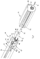
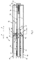
- a cargo space separator 10 has a main housing 11 and a Part housing 12 on. On its outside, the main housing 11 is by means of a housing end wall 13 completed. On or at one to the center of the device facing flange 14 of the housing end wall 13 is a hollow housing part 15 attached, which has a pull-through slot 16 for a material web 17, e.g. for a textile cloth-like web.
- a materially integrally formed protrudes from the housing end wall 13 Axle element in the form of a guide bushing 18, which is a total has circular cross-section and which with its outer wall surface Pivot bearing surface 19 for a counter-pivot bearing surface 20, formed by the circular cylindrical Inner circumferential surface of an annular bearing disc 21.
- a bearing sleeve 22 is integrally connected to the bearing disk 21, on the radial ribs 23 and on the axial ribs 24 of the inner surface 25 of a tubular winding shaft 26 is supported.
- the bearing sleeve 22 and the Bearing plate 21 together form a uniform plastic injection molded part.
- the plastic injection molded part can, for example, be designed such that two longitudinal shell halves interconnected by a film hinge the circumferential points opposite the film hinge, not shown by means of a latching hook 27 and a correlating latching web 28 each are permanently locked together.
- Winding shaft 26 and the bearing component 21, 22 are rotationally driven positively connected. To do this, it consists of sheet steel Winding shaft 26 has an axial rib 29, which is correlated in not shown Driving recesses engages in the radial ribs 23 of the bearing sleeve 22.
- the additional axis element 32 represents a circular cylindrical Steel tube, in which the housing end wall 13 facing away free end 33 inserted a plastic plug 34 and with radially inward directed notches 35 in the tube wall of the additional axle element 32 against Axial displacement is secured.
- the free end 33 of the additional axle element 32 engages in a blind hole 36 a hollow pin 37 which of the housing end wall 38 of the partial housing 12, protruding toward the center of the device, is molded on the inside.
- the additional axis element 32 is thereby within the hollow pin 37 against rotation about the Longitudinal central axis x secured that an axial rib 39 of the hollow pin 37 in an end axial slot 40 of the Additional axle elements 32 engages.
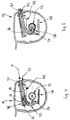
- the housing end wall 38 On its outside, the housing end wall 38 has an approximately prismatic one Approach 41, which in a pocket-like vehicle-side, not shown Bracket mount, against rotation with respect to the longitudinal central axis x secured, can intervene.
- a through the housing end wall 38 from the outside screw 42 passing through the prismatic attachment is with the plastic plug 34 screwed.
- the additional axis element 32 is thus - overall considered - tensile and pressure resistant as well as torsion-proof with the partial housing 12 connected.
- the circular cylindrical inner surface 45 of the bearing sleeve 22 extends essentially flush with the circular cylindrical inner surface 30 of the axle element 18.
- the cross-sectional contour of the non-circular cylindrical inner surface 43 The cross-sectional contour of the non-circular is similar in the mathematical sense cylindrical outer surface of the hollow part 15 of the main housing 11. Die surfaces 43, 44 which are guided into one another with a sliding fit therefore bring about a non-rotatable connection between the main housing 11 and the partial housing 12th
- a locking device 47 On the outward-facing end face 46 of the housing end wall 13 a locking device 47 is arranged. Belongs to the locking device 47 a molded in the housing end wall 13 guide receptacle 48, in which a locking element 49 is guided.
- the locking element 49 has a shaft area 50, which continued outwards through an operating handle 51 is, which passes through an axial slot 52 of the partial housing 12 transversely.
- the partial housing 12 can be operated completely independently of the operating handle 51 moved on the main housing 11 in the axial directions a and b become.
- a surrounding the additional axis element 32 is used between the guide receptacle 48 and the inside of the housing end wall 38 of the partial housing 12 supporting compression spring 57 as a compensation spring, with which installation tolerances can be taken into account if necessary.
Landscapes
- Engineering & Computer Science (AREA)
- Mechanical Engineering (AREA)
- Body Structure For Vehicles (AREA)
- Vehicle Step Arrangements And Article Storage (AREA)
- Pivots And Pivotal Connections (AREA)
- Vehicle Body Suspensions (AREA)
Applications Claiming Priority (2)
| Application Number | Priority Date | Filing Date | Title |
|---|---|---|---|
| DE19915173A DE19915173C1 (de) | 1999-04-01 | 1999-04-01 | Laderaum-Trennvorrichtung für Fahrzeuge, insbesondere für Kombinations-Personenkraftwagen |
| DE19915173 | 1999-04-01 |
Publications (3)
| Publication Number | Publication Date |
|---|---|
| EP1040964A2 true EP1040964A2 (fr) | 2000-10-04 |
| EP1040964A3 EP1040964A3 (fr) | 2001-05-09 |
| EP1040964B1 EP1040964B1 (fr) | 2005-05-25 |
Family
ID=7903450
Family Applications (1)
| Application Number | Title | Priority Date | Filing Date |
|---|---|---|---|
| EP00106619A Expired - Lifetime EP1040964B1 (fr) | 1999-04-01 | 2000-03-28 | Couvercle pour le compartiment à bagages de véhicules, en particulier véhicules familiaux |
Country Status (2)
| Country | Link |
|---|---|
| EP (1) | EP1040964B1 (fr) |
| DE (2) | DE19915173C1 (fr) |
Families Citing this family (3)
| Publication number | Priority date | Publication date | Assignee | Title |
|---|---|---|---|---|
| DE10341852B4 (de) * | 2003-09-09 | 2006-07-06 | GM Global Technology Operations, Inc., Detroit | Aufrolleinrichtung, insbesondere ein Fangnetz- oder Abdeckrollo, zur Anordnung in einem Kraftfahrzeug |
| US7392834B2 (en) | 2005-10-14 | 2008-07-01 | Bos Gmbh & Co. Kg | Protection device with replaceable adaptor parts |
| DE502006001055D1 (de) * | 2005-10-14 | 2008-08-21 | Bos Gmbh | Schutzvorrichtung mit austauschbaren Adapterteilen |
Citations (1)
| Publication number | Priority date | Publication date | Assignee | Title |
|---|---|---|---|---|
| US4168094A (en) | 1976-10-30 | 1979-09-18 | Toyota Jidosha Kogyo Kabushiki Kaisha | Device for covering up a parcel floor in an automobile |
Family Cites Families (8)
| Publication number | Priority date | Publication date | Assignee | Title |
|---|---|---|---|---|
| US4222601A (en) * | 1978-10-16 | 1980-09-16 | Irvin Industries Inc. | Automobile compartment cover |
| US4668001A (en) * | 1982-11-16 | 1987-05-26 | Nhk Spring Co., Ltd. | Securing device for a baggage cover sheet winder |
| US4671557A (en) * | 1985-10-31 | 1987-06-09 | Colt Industries Inc. | Vehicle interior cover panel means |
| US5464052A (en) * | 1993-11-08 | 1995-11-07 | Takata, Inc. | Security shade with a motor spring subassembly |
| DE4441260C2 (de) * | 1994-11-19 | 1997-05-22 | Baumeister & Ostler Gmbh Co | Laderaumabdeckung für ein Kraftfahrzeug |
| DE19621009C1 (de) * | 1996-05-24 | 1997-10-09 | Baumeister & Ostler Gmbh Co | Laderaumabdeckung für ein Kraftfahrzeug |
| US5813449A (en) * | 1997-03-19 | 1998-09-29 | Irvin Automotive Products, Inc. | Vehicle security shade with telescoping end pieces |
| US5934354A (en) * | 1997-10-23 | 1999-08-10 | Irvin Automotive Products, Inc. | Security shade support assembly |
-
1999
- 1999-04-01 DE DE19915173A patent/DE19915173C1/de not_active Expired - Fee Related
-
2000
- 2000-03-28 DE DE50010373T patent/DE50010373D1/de not_active Expired - Fee Related
- 2000-03-28 EP EP00106619A patent/EP1040964B1/fr not_active Expired - Lifetime
Patent Citations (1)
| Publication number | Priority date | Publication date | Assignee | Title |
|---|---|---|---|---|
| US4168094A (en) | 1976-10-30 | 1979-09-18 | Toyota Jidosha Kogyo Kabushiki Kaisha | Device for covering up a parcel floor in an automobile |
Also Published As
| Publication number | Publication date |
|---|---|
| EP1040964A3 (fr) | 2001-05-09 |
| EP1040964B1 (fr) | 2005-05-25 |
| DE19915173C1 (de) | 2000-05-04 |
| DE50010373D1 (de) | 2005-06-30 |
Similar Documents
| Publication | Publication Date | Title |
|---|---|---|
| DE102005007430A1 (de) | Befestigungs- und Positioniervorrichtung für einen Fahrzeugsitz | |
| DE69501940T2 (de) | Abnehmbare Befestigung eines Fahrzeugsitzuntergestells auf einem Boden | |
| DE19524531B4 (de) | Rad für einen Staubsauger | |
| EP0697311B1 (fr) | Support de rétroviseur extérieur pour véhicule | |
| DE102005049989A1 (de) | Schutzvorrichtung mit austauschbaren Adapterteilen | |
| DE69309828T2 (de) | Halterung für einklappbaren rückspiegel | |
| DE19839598A1 (de) | Befestigungshülse für einen Wandler zur geneigten Befestigung gegenüber einer Platte | |
| DE10301166B4 (de) | Laderaumabdeckung für Fahrzeuge | |
| EP2953814A1 (fr) | Système support pour ensemble siège arrière de véhicule et son procédé de montage | |
| EP1040964A2 (fr) | Couvercle pour le compartiment à bagages de véhicules, en particulier véhicules familiaux | |
| WO2011054330A1 (fr) | Cylindre hydraulique | |
| EP0223923A2 (fr) | Rétroviseur extérieur pour véhicule | |
| DE602006000439T2 (de) | Sicherheitsgurt-Aufroller und Sicherheitsgurtvorrichtung mit einem derartigen Sicherheitsgurt-Aufroller | |
| EP0728084B1 (fr) | Dispositif de guidage d'un arbre de commande et procede de montage d'un moteur avec son arbre de commande sur un vehicule | |
| EP0861757B1 (fr) | Dispositif de séparation d'un compartiment à bagages pour véhicules automobiles, en particulier pour breaks | |
| DE102006022382A1 (de) | Vorrichtung und Verfahren zur Befestigung eines Wischermotors an ein Wischergestänge | |
| DE10145240A1 (de) | Kopfstütze für Fahrzeugsitze | |
| EP1216884A2 (fr) | Dispositif adapté à recevoir un volet cache-bagages ou filet de sécurité | |
| DE29905934U1 (de) | Laderaum-Trennvorrichtung für Fahrzeuge, insbesondere für Kombinations-Personenkraftwagen | |
| DE2442351C2 (de) | In der Befestigung des Hinterachsgetriebes gegenüber dem Fahrzeugoberbau vorgesehenes elastisches Befestigungselement | |
| EP1775164A1 (fr) | Dispositif de sécurité avec des pièces d'adaptation échangeables | |
| DE102004062517A1 (de) | Befestigungsvorrichtung für eine nach vorn klappbar aushebbar ausgebildete Fondsitzlehne | |
| DE10046717A1 (de) | Schließvorrichtung für eine Fahrzeugtür | |
| DE10046630A1 (de) | Achsschenkelbolzenlagerung | |
| EP0023968A1 (fr) | Dispositif de fixation d'un amortisseur de vibrations hydraulique ou analogue dans le tube-support d'une jambe de force à ressort porteuse de roue |
Legal Events
| Date | Code | Title | Description |
|---|---|---|---|
| PUAI | Public reference made under article 153(3) epc to a published international application that has entered the european phase |
Free format text: ORIGINAL CODE: 0009012 |
|
| AK | Designated contracting states |
Kind code of ref document: A2 Designated state(s): DE ES FR GB IT SE |
|
| AX | Request for extension of the european patent |
Free format text: AL;LT;LV;MK;RO;SI |
|
| PUAL | Search report despatched |
Free format text: ORIGINAL CODE: 0009013 |
|
| AK | Designated contracting states |
Kind code of ref document: A3 Designated state(s): AT BE CH CY DE DK ES FI FR GB GR IE IT LI LU MC NL PT SE |
|
| AX | Request for extension of the european patent |
Free format text: AL;LT;LV;MK;RO;SI |
|
| 17P | Request for examination filed |
Effective date: 20010327 |
|
| AKX | Designation fees paid |
Free format text: DE ES FR GB IT SE |
|
| 17Q | First examination report despatched |
Effective date: 20030408 |
|
| RAP1 | Party data changed (applicant data changed or rights of an application transferred) |
Owner name: BOS GMBH & CO. KG |
|
| GRAP | Despatch of communication of intention to grant a patent |
Free format text: ORIGINAL CODE: EPIDOSNIGR1 |
|
| GRAS | Grant fee paid |
Free format text: ORIGINAL CODE: EPIDOSNIGR3 |
|
| GRAA | (expected) grant |
Free format text: ORIGINAL CODE: 0009210 |
|
| AK | Designated contracting states |
Kind code of ref document: B1 Designated state(s): DE ES FR GB IT SE |
|
| PG25 | Lapsed in a contracting state [announced via postgrant information from national office to epo] |
Ref country code: IT Free format text: LAPSE BECAUSE OF FAILURE TO SUBMIT A TRANSLATION OF THE DESCRIPTION OR TO PAY THE FEE WITHIN THE PRESCRIBED TIME-LIMIT;WARNING: LAPSES OF ITALIAN PATENTS WITH EFFECTIVE DATE BEFORE 2007 MAY HAVE OCCURRED AT ANY TIME BEFORE 2007. THE CORRECT EFFECTIVE DATE MAY BE DIFFERENT FROM THE ONE RECORDED. Effective date: 20050525 |
|
| REG | Reference to a national code |
Ref country code: GB Ref legal event code: FG4D Free format text: NOT ENGLISH |
|
| REF | Corresponds to: |
Ref document number: 50010373 Country of ref document: DE Date of ref document: 20050630 Kind code of ref document: P |
|
| REG | Reference to a national code |
Ref country code: SE Ref legal event code: TRGR |
|
| PG25 | Lapsed in a contracting state [announced via postgrant information from national office to epo] |
Ref country code: ES Free format text: LAPSE BECAUSE OF FAILURE TO SUBMIT A TRANSLATION OF THE DESCRIPTION OR TO PAY THE FEE WITHIN THE PRESCRIBED TIME-LIMIT Effective date: 20050905 |
|
| GBT | Gb: translation of ep patent filed (gb section 77(6)(a)/1977) |
Effective date: 20050902 |
|
| ET | Fr: translation filed | ||
| PLBE | No opposition filed within time limit |
Free format text: ORIGINAL CODE: 0009261 |
|
| STAA | Information on the status of an ep patent application or granted ep patent |
Free format text: STATUS: NO OPPOSITION FILED WITHIN TIME LIMIT |
|
| 26N | No opposition filed |
Effective date: 20060228 |
|
| PG25 | Lapsed in a contracting state [announced via postgrant information from national office to epo] |
Ref country code: DE Free format text: LAPSE BECAUSE OF NON-PAYMENT OF DUE FEES Effective date: 20061003 |
|
| PGFP | Annual fee paid to national office [announced via postgrant information from national office to epo] |
Ref country code: GB Payment date: 20080318 Year of fee payment: 9 Ref country code: SE Payment date: 20080320 Year of fee payment: 9 |
|
| PGFP | Annual fee paid to national office [announced via postgrant information from national office to epo] |
Ref country code: FR Payment date: 20080314 Year of fee payment: 9 |
|
| EUG | Se: european patent has lapsed | ||
| GBPC | Gb: european patent ceased through non-payment of renewal fee |
Effective date: 20090328 |
|
| REG | Reference to a national code |
Ref country code: FR Ref legal event code: ST Effective date: 20091130 |
|
| PG25 | Lapsed in a contracting state [announced via postgrant information from national office to epo] |
Ref country code: GB Free format text: LAPSE BECAUSE OF NON-PAYMENT OF DUE FEES Effective date: 20090328 Ref country code: FR Free format text: LAPSE BECAUSE OF NON-PAYMENT OF DUE FEES Effective date: 20091123 |
|
| PG25 | Lapsed in a contracting state [announced via postgrant information from national office to epo] |
Ref country code: SE Free format text: LAPSE BECAUSE OF NON-PAYMENT OF DUE FEES Effective date: 20090329 |