EP1040982A2 - Volant de direction, notamment de véhicule automobile - Google Patents
Volant de direction, notamment de véhicule automobile Download PDFInfo
- Publication number
- EP1040982A2 EP1040982A2 EP00104474A EP00104474A EP1040982A2 EP 1040982 A2 EP1040982 A2 EP 1040982A2 EP 00104474 A EP00104474 A EP 00104474A EP 00104474 A EP00104474 A EP 00104474A EP 1040982 A2 EP1040982 A2 EP 1040982A2
- Authority
- EP
- European Patent Office
- Prior art keywords
- steering wheel
- column switch
- contact
- steering column
- circuit board
- Prior art date
- Legal status (The legal status is an assumption and is not a legal conclusion. Google has not performed a legal analysis and makes no representation as to the accuracy of the status listed.)
- Granted
Links
- 230000005540 biological transmission Effects 0.000 claims abstract description 27
- 230000005855 radiation Effects 0.000 claims description 12
- 238000011156 evaluation Methods 0.000 claims description 11
- 238000001514 detection method Methods 0.000 claims description 4
- 238000000034 method Methods 0.000 claims 2
- 230000001960 triggered effect Effects 0.000 claims 1
- 238000010438 heat treatment Methods 0.000 abstract description 16
- 230000001105 regulatory effect Effects 0.000 abstract 1
- 239000003990 capacitor Substances 0.000 description 2
- 230000001419 dependent effect Effects 0.000 description 2
- 238000010586 diagram Methods 0.000 description 2
- 238000005485 electric heating Methods 0.000 description 2
- 210000001331 nose Anatomy 0.000 description 2
- 230000011664 signaling Effects 0.000 description 2
- 230000004913 activation Effects 0.000 description 1
- 238000005253 cladding Methods 0.000 description 1
- 230000009849 deactivation Effects 0.000 description 1
- 230000005611 electricity Effects 0.000 description 1
- 238000009434 installation Methods 0.000 description 1
- 239000010985 leather Substances 0.000 description 1
- 238000004519 manufacturing process Methods 0.000 description 1
- 239000002184 metal Substances 0.000 description 1
- 239000004033 plastic Substances 0.000 description 1
- 230000008054 signal transmission Effects 0.000 description 1
- 229920001169 thermoplastic Polymers 0.000 description 1
- 239000004416 thermosoftening plastic Substances 0.000 description 1
- 238000004804 winding Methods 0.000 description 1
Images


Classifications
-
- B—PERFORMING OPERATIONS; TRANSPORTING
- B60—VEHICLES IN GENERAL
- B60R—VEHICLES, VEHICLE FITTINGS, OR VEHICLE PARTS, NOT OTHERWISE PROVIDED FOR
- B60R16/00—Electric or fluid circuits specially adapted for vehicles and not otherwise provided for; Arrangement of elements of electric or fluid circuits specially adapted for vehicles and not otherwise provided for
- B60R16/02—Electric or fluid circuits specially adapted for vehicles and not otherwise provided for; Arrangement of elements of electric or fluid circuits specially adapted for vehicles and not otherwise provided for electric constitutive elements
- B60R16/023—Electric or fluid circuits specially adapted for vehicles and not otherwise provided for; Arrangement of elements of electric or fluid circuits specially adapted for vehicles and not otherwise provided for electric constitutive elements for transmission of signals between vehicle parts or subsystems
- B60R16/027—Electric or fluid circuits specially adapted for vehicles and not otherwise provided for; Arrangement of elements of electric or fluid circuits specially adapted for vehicles and not otherwise provided for electric constitutive elements for transmission of signals between vehicle parts or subsystems between relatively movable parts of the vehicle, e.g. between steering wheel and column
-
- B—PERFORMING OPERATIONS; TRANSPORTING
- B62—LAND VEHICLES FOR TRAVELLING OTHERWISE THAN ON RAILS
- B62D—MOTOR VEHICLES; TRAILERS
- B62D1/00—Steering controls, i.e. means for initiating a change of direction of the vehicle
- B62D1/02—Steering controls, i.e. means for initiating a change of direction of the vehicle vehicle-mounted
- B62D1/04—Hand wheels
- B62D1/06—Rims, e.g. with heating means; Rim covers
- B62D1/065—Steering wheels with heating and ventilating means
Definitions
- the invention relates to a steering wheel, in particular for a motor vehicle, with an electrical installed in the steering wheel rim Heating and with an associated steering column switch with a circuit board connected to the electrical system.
- a steering wheel with an integrated heater is from EP 0 832 806 A1 known, the steering wheel rim under its external reference a layer of thermoplastic made of synthetic or natural leather Has plastic, in which a heating wire is melted is.
- US 5 294 775 proposes a motor vehicle, in some areas electrically conductive clamping ring on the hub of the Fasten the steering wheel, from the connecting wires to the heater be performed.
- the second clamping ring is connected to the vehicle electrical system via a plug connection.
- the heating is controlled via a one Spoke assigned to the steering wheel switch for turning on or off Switch off the power supply and via a bi-metal version Thermostats placed inside the heater is.
- the object is achieved in that the hub the steering wheel carries a slip ring with contact arms a transmission module arranged on the housing of the steering column switch is in operative connection with an integrated Power control unit for heating and with on the on-board electrical system is provided with connected contacts.
- This transmission module includes all essential components, both for the electrical Connection of the heater to the vehicle electrical system as well as for power control the heating are needed. Since the anyway existing steering column switch as a receiving device for the The transmission module is used to connect the heater to the On-board electrical system can be produced inexpensively using the transmission module. Standard-equipped motor vehicles can be on simple way with an adjustable heater for the steering wheel be provided. The separate connection contacts of the transmission module allow an independent power supply to the Heating at almost any height, using the steering wheel or Steering column switch of existing electrical components not is possible.
- a variable resistance in the steering wheel is integrated, the changes as signals one of the Circuit board of the steering column switch associated evaluation electronics transferred, which these are processed and sent to transmits the power control unit, depending on on the size of the change in resistance of the heater electrical Energy is supplied.
- It is preferably used for actual temperature detection resistance built into the steering wheel a clock spring with the evaluation electronics of the circuit board the steering column switch in connection.
- the resistance is designed as a control or measuring resistor.
- the clock spring is used to transmit a horn signal from a horn switch integrated in the steering wheel to the Steering column switch existing component, its function only for signaling the resistance to the steering column switch is expanded. A separate connection between the resistance and the steering column switch is therefore not necessary.
- the control or is inserted into the steering wheel Measuring resistor is a commercially available component that is inexpensive is available and works reliably.
- the circuit board of the steering column switch comprises one a light emitting light emitting diode as a transmitter and the power control unit a photo transistor or a Photodiode as a receiver.
- the circuit board of the steering column switch comprises one a light emitting light emitting diode as a transmitter and the power control unit a photo transistor or a Photodiode as a receiver.
- the power control unit comprises to evaluate the light radiation with the phototransistor or the photodiode coupled power transistor. Because of this measure, the control loop closed between the heating of the steering wheel and the electrical system.
- the power transistor enables a supply of the Heating the steering wheel up to a certain actual temperature required electricity or the supply of for heating of the steering wheel required power from the electrical system.
- the power control unit the contact arms and the Terminal contacts assigned to a common circuit board. This will reduce the manufacturing costs through the provision a compact unit, reduced.
- the circuit board of a substantially U-shaped Surround the housing with a lid that is in the range of Connection contacts has a connector coding, the Contact arms on the opposite of the connection contacts Protrude down the front of the housing.
- the cover expediently has in the region of the phototransistor an opening for the passage of light radiation, that with a corresponding opening of the steering column switch corresponds to which the LED is assigned.
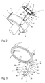
- the steering wheel includes an electrical integrated in the steering wheel rim Heater 12 connected to a slip ring 1 stands.
- the slip ring points to the steering wheel 1 clip arms 2 on the front.
- For electrical connection with the heater are two contacts on the slip ring 1 3 arranged with ring contacts 4 of the slip ring 1 in Connect.
- the ring contacts 4 are in the clip arms 2 opposite end of the slip ring 1 embedded.
- the contacts 3 are on the same end face the slip ring 1.
- the steering column switch 5 has lateral receptacles 6 in a housing 7 for shift levers to be used. Furthermore, in that Housing 7 of the steering column switch 5 a rotatably mounted coil spring 8 for the transmission of switching functions on the steering wheel side integrated.
- the winding spring 8 carries two on the end face Driver 9 and contacts 11 surrounded by a collar 10 for the switching functions.
- the housing 7 of the steering column switch 5 is a transmission module 13 assigned to the heater 12.
- the transmission module 13 is provided with two contact arms 14, 15 which each with one of the ring contacts 4 of the slip ring 1 in Stand in active connection and are designed as leaf springs.
- the ends 16 are on a printed circuit board 17 fixed contact arms 14, 15 angled such that they protrude into an area below the slip ring 1.
- the free legs 19, 20 each carrying a contact 18 the contact arms 14, 15 are of different lengths, so that the contact 18 of the leg 19 of the contact arm 14 on the inner ring contact 4 and the contact 18 of the leg 20 of the contact arm 15 on the outer ring contact 4 of the Slip ring 1 rests.
- the circuit board 17 of the transmission module 13 is still with a power control unit 21 for the heater 12 provided and carries on the contact arms 14, 15 opposite End two connection contacts 22 for connection with the vehicle electrical system.
- the power control unit 21 serves as both an interface between the heater 12 of the steering wheel and the electrical system as well as between a circuit board, not shown Steering column switch 5 and the heater 12, the transmission a signal from the steering column switch circuit board 5 to the power control unit 21 by means of light radiation 23 done without contact.
- the circuit board 17 of the transmission module 13 is one essentially surround U-shaped housing 24, which is in the area the connection contacts 22 has a connector coding 25 and provided on the long sides 26 of its legs 27 with webs 28 is in corresponding grooves 29 of the housing 7 of the Engage the steering column switch 5. Between the legs 27 of the Housing 24 has a cover 30 inserted on the longitudinal side Legs 31 clip noses 32, which in corresponding Intervene clip openings 33 of the housing 24. The fixation the circuit board 17 takes place between webs 34 of the Cover and webs 35 of the housing 24 in the clipped state. To enable light radiation 23 to pass through the cover facing the housing 7 of the steering column switch 5 30 with an opening 36 in the area of the power control unit 21 provided with an opening 37 in the housing 7 of the Steering column switch 5 is arranged congruently.
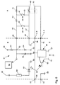
- the operation of the signal transmission is as follows 6 by means of the circuit diagram, the area A functions of the steering wheel, the area B functions the steering column switch 5 and the area C functions of the transmission module represents.
- the steering wheel is a switch 38 for actuating a horn as well in parallel, a switch 39 for activation or deactivation assigned to the heater.
- a resistor 42 switched between the contact 40 of the Switch 38 and the contact 41 switch 39.
- resistors 44, 45 connected in series, the resistor 45 as a variable, temperature-dependent resistor designed to detect the actual temperature of the heater 12 which is represented by a resistor.
- the current paths 46, 47 of the switches 38, 39 lead to contacts 48, 49 of the clock spring 8, the contact 49 in a ground contact 50 flows.
- Contact 48 leads to a voltage divider 51 on the circuit board of the steering column switch 5 whose first node 52, the resistors 53, 54 in series between a ground contact 55 and a voltage contact 56 are arranged are.
- the contact 48 leads to a voltage contact 57, between them and a Ground contact 58 a capacitor 59 is connected.
- the switch 38 for the horn and the switch 39 for the Heating systems are usually open. During the short-term Actuation, the switch 38 provides a ground potential and the switch 39 has a voltage potential. If the two Switches 38, 39 are open, evaluation electronics 60 or a processor of the steering column switch circuit board 5 evaluate the actual value of the temperature-dependent resistor 45 and a corresponding signal to a light emitting diode 61 send that between a voltage contact 62 and a ground contact 63 is connected in series with a resistor 64.
- the evaluation electronics 60 specifies a reference variable that with the actual value of the signal of the resistor 45, which the Temperature of the heating corresponds, is compared. At a Deviation of the actual value of the signal of the resistor 45 from the guide size of the evaluation electronics 60 sends the Light-emitting diode 61 a correspondingly modulated light radiation 23 to a phototransistor 65, which is part of the power control unit 21 of the transmission module 13.
- the one Ground contact 70 connected phototransistor 65 drives a power transistor 66, which is also part the power control unit 21 of the transmission module 13 is.
- the power transistor 66 in turn includes one Current path between the two ground contacts 67, 68 and the Voltage contact 69, with the ground contact 68 and the voltage contact 69 through a connection contact 22, the is directly connected to the vehicle electrical system are.
- connection contact 22 which is designed as a voltage contact 69
- contact arm 14 which acts on one of the ring contacts 4 and the with the ring contact 4 coupled contact 3 the heater 12.
- the voltage from the heater 12 is via the second contact 3, which is also coupled to the other ring contact 4, via the contact arm 15 to the power transistor 66 Power control unit 21 passed. Via the power transistor 66 the voltage reaches the ground contact 68, which represents the second connection contact 22 to the vehicle electrical system.
- the light emitting diode 61 does not transmit any light radiation 23 off and the power transistor 66 interrupts the Heating current path 12.
Landscapes
- Engineering & Computer Science (AREA)
- Mechanical Engineering (AREA)
- Chemical & Material Sciences (AREA)
- Combustion & Propulsion (AREA)
- Transportation (AREA)
- Steering Controls (AREA)
Applications Claiming Priority (2)
| Application Number | Priority Date | Filing Date | Title |
|---|---|---|---|
| DE19914176 | 1999-03-29 | ||
| DE19914176A DE19914176A1 (de) | 1999-03-29 | 1999-03-29 | Lenkrad, insbesondere für ein Kraftfahrzeug |
Publications (3)
| Publication Number | Publication Date |
|---|---|
| EP1040982A2 true EP1040982A2 (fr) | 2000-10-04 |
| EP1040982A3 EP1040982A3 (fr) | 2001-09-19 |
| EP1040982B1 EP1040982B1 (fr) | 2004-01-21 |
Family
ID=7902797
Family Applications (1)
| Application Number | Title | Priority Date | Filing Date |
|---|---|---|---|
| EP00104474A Expired - Lifetime EP1040982B1 (fr) | 1999-03-29 | 2000-03-08 | Volant de direction, notamment de véhicule automobile |
Country Status (2)
| Country | Link |
|---|---|
| EP (1) | EP1040982B1 (fr) |
| DE (2) | DE19914176A1 (fr) |
Cited By (3)
| Publication number | Priority date | Publication date | Assignee | Title |
|---|---|---|---|---|
| FR2835498A1 (fr) * | 2002-01-04 | 2003-08-08 | Delphi Tech Inc | Volant a chauffage electrique pour vehicule |
| WO2011018500A1 (fr) | 2009-08-14 | 2011-02-17 | Takata-Petri Ag | Dispositif de direction pour un véhicule automobile présentant un volant et une unité de contact électrique |
| TWI903727B (zh) * | 2024-09-02 | 2025-11-01 | 統亞電子科技股份有限公司 | 可方便組設於不同車種之加熱方向盤結構 |
Citations (2)
| Publication number | Priority date | Publication date | Assignee | Title |
|---|---|---|---|---|
| US5294775A (en) | 1992-03-09 | 1994-03-15 | Claude Carrier | Thermostatically controlled electrically heated steering wheel cover assembly |
| EP0832806A1 (fr) | 1996-09-27 | 1998-04-01 | TRW Occupant Restraint Systems GmbH | Volant de direction avec volant à chauffage intégré |
Family Cites Families (4)
| Publication number | Priority date | Publication date | Assignee | Title |
|---|---|---|---|---|
| DE4125293C1 (fr) * | 1991-07-31 | 1992-12-03 | Kabelwerke Reinshagen Gmbh, 5600 Wuppertal, De | |
| DE19602060A1 (de) * | 1996-01-20 | 1997-07-24 | Teves Gmbh Alfred | An den Lenkstock bzw. an das Lenkrad eines Kraftfahrzeugs anbaubare integrierte Baugruppe |
| DE19643451A1 (de) * | 1996-02-27 | 1997-08-28 | Petri Ag | Verfahren und Vorrichtung zur berührungslosen Übertragung elektrischer Energie und von Daten in Kraftfahrzeugen |
| DE19649910C2 (de) * | 1996-12-02 | 2000-03-23 | Trw Fahrzeugelektrik | Vorrichtung zur Signalübertragung von und zu am Lenkrad eines KFZ vorgesehenen Funktionseinheiten |
-
1999
- 1999-03-29 DE DE19914176A patent/DE19914176A1/de not_active Withdrawn
-
2000
- 2000-03-08 DE DE50005057T patent/DE50005057D1/de not_active Expired - Lifetime
- 2000-03-08 EP EP00104474A patent/EP1040982B1/fr not_active Expired - Lifetime
Patent Citations (2)
| Publication number | Priority date | Publication date | Assignee | Title |
|---|---|---|---|---|
| US5294775A (en) | 1992-03-09 | 1994-03-15 | Claude Carrier | Thermostatically controlled electrically heated steering wheel cover assembly |
| EP0832806A1 (fr) | 1996-09-27 | 1998-04-01 | TRW Occupant Restraint Systems GmbH | Volant de direction avec volant à chauffage intégré |
Cited By (5)
| Publication number | Priority date | Publication date | Assignee | Title |
|---|---|---|---|---|
| FR2835498A1 (fr) * | 2002-01-04 | 2003-08-08 | Delphi Tech Inc | Volant a chauffage electrique pour vehicule |
| WO2011018500A1 (fr) | 2009-08-14 | 2011-02-17 | Takata-Petri Ag | Dispositif de direction pour un véhicule automobile présentant un volant et une unité de contact électrique |
| DE102009037672A1 (de) * | 2009-08-14 | 2011-02-17 | Takata-Petri Ag | Lenkvorrichtung für ein Kraftfahrzeug mit einem Lenkrad und einer elektronischen Kontakteinheit |
| DE102009037672B4 (de) * | 2009-08-14 | 2014-01-16 | TAKATA Aktiengesellschaft | Lenkvorrichtung für ein Kraftfahrzeug mit einem Lenkrad und einer elektronischen Kontakteinheit |
| TWI903727B (zh) * | 2024-09-02 | 2025-11-01 | 統亞電子科技股份有限公司 | 可方便組設於不同車種之加熱方向盤結構 |
Also Published As
| Publication number | Publication date |
|---|---|
| DE50005057D1 (de) | 2004-02-26 |
| DE19914176A1 (de) | 2000-10-05 |
| EP1040982B1 (fr) | 2004-01-21 |
| EP1040982A3 (fr) | 2001-09-19 |
Similar Documents
| Publication | Publication Date | Title |
|---|---|---|
| DE69231446T2 (de) | Intelligente lampe oder intelligenter kontakt für eine lampe | |
| EP1873800B1 (fr) | Machine-outil électrique et interrupteur correspondant | |
| DE4322249A1 (de) | Bus-Schalter | |
| WO1999013341A1 (fr) | Dispositif detecteur | |
| EP0393233B1 (fr) | Système de transmission de signaux | |
| EP1202024A1 (fr) | Module de capteur avec une plaque de métal découpée ( capteur magnéto résistif vanne papillon ) | |
| DE19955070A1 (de) | Schalteranordnung für ein Kraftfahrzeug | |
| EP1213189B1 (fr) | Dispositif pour surveiller le réseau de bord d'un véhicule | |
| EP1040982B1 (fr) | Volant de direction, notamment de véhicule automobile | |
| EP1286478B1 (fr) | Système de capteur tactile avec transpondeur | |
| EP0736419B1 (fr) | Dispositif pour la commande d'au moins un appareil monté dans un véhicule | |
| DE102019203111A1 (de) | Kraftfahrzeugsteuergerät mit Zu- und Abschaltfunktion für mindestens einen von dem Kraftfahrzeugsteuergerät anzusteuernden, elektrischen Verbraucher | |
| EP1739266A2 (fr) | Système de commande d'un lève-vitre de véhicule | |
| DE3905422C2 (fr) | ||
| EP0525484B1 (fr) | Circuit de commande pour un volant de direction chauffant électriquement dans un véhicule automobile | |
| EP3633866A1 (fr) | Composant pour un véhicule | |
| EP1776518B1 (fr) | Capteur pour mesurer la position d'un element de reglage | |
| EP0208318A2 (fr) | Circuit électrique commandé par la température | |
| EP0292759B1 (fr) | Dispositif anti-vol pour véhicules automobiles | |
| EP1556268B1 (fr) | Volant de vehicule automobile comprenant un module de coussin gonflable integre | |
| EP0844701B1 (fr) | Connecteur à fiche multipolaire | |
| DE19733404B4 (de) | Vorrichtung zur Signalverarbeitung in einem Kraftfahrzeug | |
| DE19833927C1 (de) | Elektrisches Steckverbindungsteil zum Anschluß eines elektrischen Verbrauchers | |
| DE10061024A1 (de) | Mehrstellungs-Schalter in Kraftfahrzeugen | |
| WO2003045745A1 (fr) | Entraînement d'essuie-glace |
Legal Events
| Date | Code | Title | Description |
|---|---|---|---|
| PUAI | Public reference made under article 153(3) epc to a published international application that has entered the european phase |
Free format text: ORIGINAL CODE: 0009012 |
|
| AK | Designated contracting states |
Kind code of ref document: A2 Designated state(s): AT BE CH CY DE DK ES FI FR GB GR IE IT LI LU MC NL PT SE Kind code of ref document: A2 Designated state(s): DE ES FR GB IT |
|
| AX | Request for extension of the european patent |
Free format text: AL;LT;LV;MK;RO;SI |
|
| PUAL | Search report despatched |
Free format text: ORIGINAL CODE: 0009013 |
|
| AK | Designated contracting states |
Kind code of ref document: A3 Designated state(s): AT BE CH CY DE DK ES FI FR GB GR IE IT LI LU MC NL PT SE |
|
| AX | Request for extension of the european patent |
Free format text: AL;LT;LV;MK;RO;SI |
|
| 17P | Request for examination filed |
Effective date: 20020315 |
|
| AKX | Designation fees paid |
Free format text: DE ES FR GB IT |
|
| RAP1 | Party data changed (applicant data changed or rights of an application transferred) |
Owner name: DELPHI TECHNOLOGIES INC. |
|
| GRAP | Despatch of communication of intention to grant a patent |
Free format text: ORIGINAL CODE: EPIDOSNIGR1 |
|
| GRAS | Grant fee paid |
Free format text: ORIGINAL CODE: EPIDOSNIGR3 |
|
| GRAA | (expected) grant |
Free format text: ORIGINAL CODE: 0009210 |
|
| AK | Designated contracting states |
Kind code of ref document: B1 Designated state(s): DE ES FR GB IT |
|
| PG25 | Lapsed in a contracting state [announced via postgrant information from national office to epo] |
Ref country code: IT Free format text: LAPSE BECAUSE OF FAILURE TO SUBMIT A TRANSLATION OF THE DESCRIPTION OR TO PAY THE FEE WITHIN THE PRESCRIBED TIME-LIMIT;WARNING: LAPSES OF ITALIAN PATENTS WITH EFFECTIVE DATE BEFORE 2007 MAY HAVE OCCURRED AT ANY TIME BEFORE 2007. THE CORRECT EFFECTIVE DATE MAY BE DIFFERENT FROM THE ONE RECORDED. Effective date: 20040121 Ref country code: GB Free format text: LAPSE BECAUSE OF FAILURE TO SUBMIT A TRANSLATION OF THE DESCRIPTION OR TO PAY THE FEE WITHIN THE PRESCRIBED TIME-LIMIT Effective date: 20040121 |
|
| REG | Reference to a national code |
Ref country code: GB Ref legal event code: FG4D Free format text: NOT ENGLISH |
|
| REF | Corresponds to: |
Ref document number: 50005057 Country of ref document: DE Date of ref document: 20040226 Kind code of ref document: P |
|
| PG25 | Lapsed in a contracting state [announced via postgrant information from national office to epo] |
Ref country code: ES Free format text: LAPSE BECAUSE OF FAILURE TO SUBMIT A TRANSLATION OF THE DESCRIPTION OR TO PAY THE FEE WITHIN THE PRESCRIBED TIME-LIMIT Effective date: 20040502 |
|
| GBV | Gb: ep patent (uk) treated as always having been void in accordance with gb section 77(7)/1977 [no translation filed] |
Effective date: 20040121 |
|
| ET | Fr: translation filed | ||
| PLBE | No opposition filed within time limit |
Free format text: ORIGINAL CODE: 0009261 |
|
| STAA | Information on the status of an ep patent application or granted ep patent |
Free format text: STATUS: NO OPPOSITION FILED WITHIN TIME LIMIT |
|
| 26N | No opposition filed |
Effective date: 20041022 |
|
| REG | Reference to a national code |
Ref country code: DE Ref legal event code: R082 Ref document number: 50005057 Country of ref document: DE Representative=s name: JOCHEN MUELLER, DE Ref country code: DE Ref legal event code: R082 Ref document number: 50005057 Country of ref document: DE Representative=s name: MUELLER, JOCHEN, DIPL.-ING., DE |
|
| REG | Reference to a national code |
Ref country code: FR Ref legal event code: PLFP Year of fee payment: 16 |
|
| REG | Reference to a national code |
Ref country code: FR Ref legal event code: PLFP Year of fee payment: 17 |
|
| PGFP | Annual fee paid to national office [announced via postgrant information from national office to epo] |
Ref country code: FR Payment date: 20160328 Year of fee payment: 17 |
|
| PGFP | Annual fee paid to national office [announced via postgrant information from national office to epo] |
Ref country code: DE Payment date: 20160331 Year of fee payment: 17 |
|
| REG | Reference to a national code |
Ref country code: DE Ref legal event code: R119 Ref document number: 50005057 Country of ref document: DE |
|
| REG | Reference to a national code |
Ref country code: FR Ref legal event code: ST Effective date: 20171130 |
|
| PG25 | Lapsed in a contracting state [announced via postgrant information from national office to epo] |
Ref country code: FR Free format text: LAPSE BECAUSE OF NON-PAYMENT OF DUE FEES Effective date: 20170331 Ref country code: DE Free format text: LAPSE BECAUSE OF NON-PAYMENT OF DUE FEES Effective date: 20171003 |