EP1556268B1 - Volant de vehicule automobile comprenant un module de coussin gonflable integre - Google Patents
Volant de vehicule automobile comprenant un module de coussin gonflable integre Download PDFInfo
- Publication number
- EP1556268B1 EP1556268B1 EP03773558A EP03773558A EP1556268B1 EP 1556268 B1 EP1556268 B1 EP 1556268B1 EP 03773558 A EP03773558 A EP 03773558A EP 03773558 A EP03773558 A EP 03773558A EP 1556268 B1 EP1556268 B1 EP 1556268B1
- Authority
- EP
- European Patent Office
- Prior art keywords
- steering wheel
- current paths
- airbag
- wheel according
- airbag carrier
- Prior art date
- Legal status (The legal status is an assumption and is not a legal conclusion. Google has not performed a legal analysis and makes no representation as to the accuracy of the status listed.)
- Expired - Lifetime
Links
- 229920003023 plastic Polymers 0.000 claims description 6
- 239000004033 plastic Substances 0.000 claims description 6
- 230000008878 coupling Effects 0.000 claims description 4
- 238000010168 coupling process Methods 0.000 claims description 4
- 238000005859 coupling reaction Methods 0.000 claims description 4
- RYGMFSIKBFXOCR-UHFFFAOYSA-N Copper Chemical compound [Cu] RYGMFSIKBFXOCR-UHFFFAOYSA-N 0.000 claims description 3
- 229910052802 copper Inorganic materials 0.000 claims description 3
- 239000010949 copper Substances 0.000 claims description 3
- 239000004020 conductor Substances 0.000 claims 2
- 239000000463 material Substances 0.000 claims 1
- 238000000034 method Methods 0.000 claims 1
- 239000003973 paint Substances 0.000 claims 1
- 238000005516 engineering process Methods 0.000 description 3
- 238000004519 manufacturing process Methods 0.000 description 3
- 238000009434 installation Methods 0.000 description 2
- 239000011810 insulating material Substances 0.000 description 2
- 238000007792 addition Methods 0.000 description 1
- 230000005540 biological transmission Effects 0.000 description 1
- 238000004891 communication Methods 0.000 description 1
- 238000013461 design Methods 0.000 description 1
- 238000011156 evaluation Methods 0.000 description 1
- 238000001746 injection moulding Methods 0.000 description 1
- 239000004922 lacquer Substances 0.000 description 1
- 239000002184 metal Substances 0.000 description 1
- 229910052751 metal Inorganic materials 0.000 description 1
- 238000000926 separation method Methods 0.000 description 1
- 238000012549 training Methods 0.000 description 1
- 238000004804 winding Methods 0.000 description 1
Images

Classifications
-
- B—PERFORMING OPERATIONS; TRANSPORTING
- B60—VEHICLES IN GENERAL
- B60R—VEHICLES, VEHICLE FITTINGS, OR VEHICLE PARTS, NOT OTHERWISE PROVIDED FOR
- B60R21/00—Arrangements or fittings on vehicles for protecting or preventing injuries to occupants or pedestrians in case of accidents or other traffic risks
- B60R21/02—Occupant safety arrangements or fittings, e.g. crash pads
- B60R21/16—Inflatable occupant restraints or confinements designed to inflate upon impact or impending impact, e.g. air bags
- B60R21/20—Arrangements for storing inflatable members in their non-use or deflated condition; Arrangement or mounting of air bag modules or components
- B60R21/203—Arrangements for storing inflatable members in their non-use or deflated condition; Arrangement or mounting of air bag modules or components in steering wheels or steering columns
- B60R21/2035—Arrangements for storing inflatable members in their non-use or deflated condition; Arrangement or mounting of air bag modules or components in steering wheels or steering columns using modules containing inflator, bag and cover attachable to the steering wheel as a complete sub-unit
- B60R21/2037—Arrangements for storing inflatable members in their non-use or deflated condition; Arrangement or mounting of air bag modules or components in steering wheels or steering columns using modules containing inflator, bag and cover attachable to the steering wheel as a complete sub-unit the module or a major component thereof being yieldably mounted, e.g. for actuating the horn switch or for protecting the driver in a non-deployment situation
-
- B—PERFORMING OPERATIONS; TRANSPORTING
- B60—VEHICLES IN GENERAL
- B60Q—ARRANGEMENT OF SIGNALLING OR LIGHTING DEVICES, THE MOUNTING OR SUPPORTING THEREOF OR CIRCUITS THEREFOR, FOR VEHICLES IN GENERAL
- B60Q1/00—Arrangement of optical signalling or lighting devices, the mounting or supporting thereof or circuits therefor
- B60Q1/02—Arrangement of optical signalling or lighting devices, the mounting or supporting thereof or circuits therefor the devices being primarily intended to illuminate the way ahead or to illuminate other areas of way or environments
- B60Q1/04—Arrangement of optical signalling or lighting devices, the mounting or supporting thereof or circuits therefor the devices being primarily intended to illuminate the way ahead or to illuminate other areas of way or environments the devices being headlights
- B60Q1/14—Arrangement of optical signalling or lighting devices, the mounting or supporting thereof or circuits therefor the devices being primarily intended to illuminate the way ahead or to illuminate other areas of way or environments the devices being headlights having dimming means
- B60Q1/1446—Arrangement of optical signalling or lighting devices, the mounting or supporting thereof or circuits therefor the devices being primarily intended to illuminate the way ahead or to illuminate other areas of way or environments the devices being headlights having dimming means controlled by mechanically actuated switches
- B60Q1/1453—Hand actuated switches
- B60Q1/1461—Multifunction switches for dimming headlights and controlling additional devices, e.g. for controlling direction indicating lights
- B60Q1/1484—Multifunction switches for dimming headlights and controlling additional devices, e.g. for controlling direction indicating lights mounted on the steering wheel
-
- B—PERFORMING OPERATIONS; TRANSPORTING
- B62—LAND VEHICLES FOR TRAVELLING OTHERWISE THAN ON RAILS
- B62D—MOTOR VEHICLES; TRAILERS
- B62D1/00—Steering controls, i.e. means for initiating a change of direction of the vehicle
- B62D1/02—Steering controls, i.e. means for initiating a change of direction of the vehicle vehicle-mounted
- B62D1/04—Hand wheels
-
- B—PERFORMING OPERATIONS; TRANSPORTING
- B29—WORKING OF PLASTICS; WORKING OF SUBSTANCES IN A PLASTIC STATE IN GENERAL
- B29C—SHAPING OR JOINING OF PLASTICS; SHAPING OF MATERIAL IN A PLASTIC STATE, NOT OTHERWISE PROVIDED FOR; AFTER-TREATMENT OF THE SHAPED PRODUCTS, e.g. REPAIRING
- B29C45/00—Injection moulding, i.e. forcing the required volume of moulding material through a nozzle into a closed mould; Apparatus therefor
- B29C45/14—Injection moulding, i.e. forcing the required volume of moulding material through a nozzle into a closed mould; Apparatus therefor incorporating preformed parts or layers, e.g. injection moulding around inserts or for coating articles
- B29C45/14639—Injection moulding, i.e. forcing the required volume of moulding material through a nozzle into a closed mould; Apparatus therefor incorporating preformed parts or layers, e.g. injection moulding around inserts or for coating articles for obtaining an insulating effect, e.g. for electrical components
-
- B—PERFORMING OPERATIONS; TRANSPORTING
- B29—WORKING OF PLASTICS; WORKING OF SUBSTANCES IN A PLASTIC STATE IN GENERAL
- B29K—INDEXING SCHEME ASSOCIATED WITH SUBCLASSES B29B, B29C OR B29D, RELATING TO MOULDING MATERIALS OR TO MATERIALS FOR MOULDS, REINFORCEMENTS, FILLERS OR PREFORMED PARTS, e.g. INSERTS
- B29K2995/00—Properties of moulding materials, reinforcements, fillers, preformed parts or moulds
- B29K2995/0003—Properties of moulding materials, reinforcements, fillers, preformed parts or moulds having particular electrical or magnetic properties, e.g. piezoelectric
- B29K2995/0005—Conductive
-
- B—PERFORMING OPERATIONS; TRANSPORTING
- B29—WORKING OF PLASTICS; WORKING OF SUBSTANCES IN A PLASTIC STATE IN GENERAL
- B29L—INDEXING SCHEME ASSOCIATED WITH SUBCLASS B29C, RELATING TO PARTICULAR ARTICLES
- B29L2031/00—Other particular articles
- B29L2031/34—Electrical apparatus, e.g. sparking plugs or parts thereof
- B29L2031/3493—Moulded interconnect devices, i.e. moulded articles provided with integrated circuit traces
Definitions
- the invention relates to a steering wheel of a motor vehicle with an integrated airbag module comprising an airbag carrier covered by a folded airbag, at least one steering wheel switch and an electrical connecting device designed as a slip ring contact arrangement or a winding spring to a vehicle electrical system.
- a switch unit with a attachable to a jacket tube of the steering column carrier housing for receiving different, each provided with a separate electrical supply line or a separate line tree single switch is known.
- Each individual switch is guided by means of projections formed in the form of springs in grooves of the carrier housing and held by means of clip connections in its position.
- the carrier housing has a resilient horn contact whose connection takes place from the side of the jacket tube via a further line to which a contact part is crimped. The circuit is closed via a ground connection of the steering wheel. When mounting the steering wheel, it must be ensured that the connection of the horn contact is not interrupted.
- the individual electrical connections for the individual switches and the horn contact are relatively expensive and increase the possibility of errors during assembly or during repair of the switch unit.
- a steering wheel switch for a motor vehicle having a plurality of individual switches and a carrier housing arranged within the steering wheel for receiving an airbag module, via which at least one horn switch can be acted upon.
- a support plate is fixed, on which spring-loaded, wobbling the carrier housing is supported, wherein on the support housing on the side facing the support plate, a contact unit is attached with terminal contacts, the individual switch contacting switch guides and arranged on connecting lines Hupenschalter via connecting lines.
- the object is achieved in that the airbag carrier has current paths for coupling the connecting device with the steering wheel switch.
- the connecting device can be designed, for example, as a slip ring contact arrangement or a so-called clock spring (clock spring) and integrated in a jacket tube-fixed steering column module, the steering wheel or a separate housing. It is also possible, in addition to the at least one steering wheel switch to integrate a display device in the steering wheel and to couple via the current paths of the airbag carrier with the electrical system. Of course, the current paths can serve not only the power supply but also the data exchange.
- the airbag carrier is preferably provided with at least two mutually spaced tabs for attachment and electrical contacting of steering wheel switches.
- the spacing of the tabs from each other, for example, is such that between the tabs of the airbag can be accommodated with a same spanning cover.
- each of the lugs comprises a pointing in the direction of the associated steering wheel switch connector with terminal contacts, the terminal contacts are connected to a contact with the steering wheel switch and the other with the current paths.
- the electrical connection is thus by simply plugging the steering wheel switch on the Plug connection of the airbag carrier to accomplish.
- each of the tabs preferably has an integrally formed therewith housing of the steering wheel switch for receiving switching contacts and for supporting at least one actuating element.
- a plug for coupling with plug contacts of the connecting device is formed on the airbag carrier.
- the plug of the bag carrier is connected to the current paths.
- the connecting device is connected to a central circuit board of a jacket tube fixed steering column module with steering column switches, which in turn is connected to the electrical system.
- the central circuit board may for example be assigned electronic components for evaluating the signals received via the current paths and the connection device from the steering wheel switches, so that the steering wheel switches only require a small installation space in the steering wheel and essential functions are placed outside the steering wheel.
- the airbag carrier has at least one horn contact, which is connected via the current paths to the connecting device.
- the horn contact for connection to the electrical system or the connection device is not to be cabled separately. The contacting takes place instead via the current paths of the airbag carrier.
- the airbag carrier is made of plastic. This ensures a direct assignment of the current paths to the airbag carrier, since the airbag carrier itself is made of an insulating material.
- the current paths are formed as stamped grid, which is injected with the release of contact zones for the connection contacts and / or the plug in the airbag carrier.
- the current paths are thus essentially embedded in the plastic of the airbag housing and thus simultaneously electrically insulated.
- the current paths are preferably manufactured together with the airbag carrier in MID technology.
- MID technology molded interconnect devices
- MID molded interconnect devices
- two-component injection molding technology in which the functions airbag carrier or housing, circuit board and plug-in connections are combined in one component.
- one of the plastic components by additions either be self-conductive or metallizable.
- the current paths advantageously consist of a conductive lacquer provided with copper and applied to the airbag carrier.
- the conductive ink is screen printed on the airbag carrier and determines the layout of the current paths. After applying the conductive ink, this is provided with copper.
- the current paths are part of a flexible printed circuit board mounted on the airbag carrier.
- the current paths are almost completely enveloped by the insulating material of the printed circuit board, which is glued to the made of a metal or plastic airbag carrier, for example, with the flexible circuit board adapts to the contour of the airbag carrier.
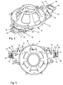
- the steering wheel 1 of a motor vehicle has a steering wheel rim 2, which is connected via steering wheel spokes 3 with a steering wheel bowl 5 accommodating an airbag module 4.
- the airbag module 4 comprises a cover 5 for an airbag 6, which is arranged in the folded state by means of a retaining ring 7 on an airbag carrier 8 made of plastic above a gas generator 9.
- an unillustrated steering column module with steering column switches and with a central circuit board is arranged jacket tube fixed, which receives an electrical connection device.
- the steering wheel 1, two opposite switch units 10 are assigned, each comprising a plurality of individual steering wheel switch 11, of which the actuating elements 20 can be seen.
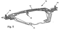
- the connecting device has the airbag carrier 8 as overmolded punched grid 12 formed current paths 13, on the one hand with terminal contacts 14 of connectors 15 for the steering wheel switch 11 and the other with a plug 16 for as so said clockspring trained connecting means are in communication.
- the connectors 15 are formed integrally with the airbag carrier 8 connected tabs 17, which have both mounting holes 18 for the steering wheel switch 11 comprehensive switch units 10 and separation points 19 for the current paths 13.
- the switching signals of the steering wheel switch 11 are transmitted for evaluation via the current paths 13 and the connecting device to the printed circuit board of the steering column module and get from there to the electrical system of the motor vehicle.
Landscapes
- Engineering & Computer Science (AREA)
- Mechanical Engineering (AREA)
- Chemical & Material Sciences (AREA)
- Combustion & Propulsion (AREA)
- Transportation (AREA)
- Air Bags (AREA)
Claims (13)
- Volant de direction d'un véhicule avec un module d'airbag intégré (4) qui comprend un support d'airbag (8) recouvert d'un airbag (6) plié, au moins un commutateur de volant de direction (11) et un dispositif de liaison électrique formé comme un agencement de contact à bague glissante ou un ressort spiral sur un réseau de bord, caractérisé en ce que le support d'airbag (8) présente des chemins de courant (13) pour coupler le dispositif de liaison au commutateur de volant de direction (11).
- Volant de direction selon la revendication 1, caractérisé en ce que le support d'airbag (8) est muni d'au moins deux pattes (17) distantes l'une de l'autre pour la fixation et le contact électrique de commutateurs de volant de direction (11).
- Volant de direction selon la revendication 2, caractérisé en ce que chacune des pattes (17) comprend une liaison à fiches (15) avec des contacts de connexion (14), orienté dans la direction du commutateur de volant de direction (11) associée, les contacts de connexion (14) étant reliés d'une part à des contacts du commutateur de volant de direction (11) et d'autre part aux chemins de courant (13).
- Volant de direction selon la revendication 2 ou 3, caractérisé en ce que chacune des pattes (17) présente un boîtier du commutateur de volant de direction (11) formant ainsi un monobloc pour recevoir des contacts de connexion ainsi que pour placer au moins un élément de fixation (20).
- Volant de direction selon l'une des revendications 1 à 4, caractérisé en ce que sur le support d'airbag (8) est formé un connecteur (16) pour le couplage avec des contacts de connexion du dispositif de liaison.
- Volant de direction selon la revendication 5, caractérisé en ce que le connecteur (16) du support d'airbag (8) est relié aux chemins de courant (13).
- Volant de direction selon l'une des revendications 1 à 6, caractérisé en ce que le dispositif de liaison est relié à une plaque de conducteur centrale d'un module d'arbre de direction renforcé par un tube-corps avec des contacts d'arbre de direction qui à leur tour sont connectés au réseau de bord.
- Volant de direction selon l'une des revendications 1 à 7, caractérisé en ce que le support d'airbag (8) présente au moins un contact d'avertisseur qui est connecté par les chemins de courant (13) au dispositif de liaison.
- Volant de direction selon l'une des revendications 1 à 8, caractérisé en ce que le support d'airbag (8) est fabriqué en matière plastique.
- Volant de direction selon l'une des revendications 1 à 9, caractérisé en ce que les chemins de courant (13) sont formés comme une grille estampée (12) qui est injectée dans le support d'airbag (8) lorsque les zones de contact des contacts de connexion (14) et/ou du connecteur sont libérées.
- Volant de direction selon l'une des revendications 1 à 9, caractérisé en ce que les chemins de courant (13) conjointement avec le support d'airbag (8) sont fabriqués en technique MID.
- Volant de direction selon l'une des revendications 1 à 8, caractérisé en ce que les chemins de courant (13) sont composés d'un vernis conducteur muni de cuivre placé sur le support d'airbag (8).
- Volant de direction selon l'une des revendications 1 à 9, caractérisé en ce que les chemins de courant (13) sont une partie constitutive d'une plaque de conducteur flexible fixée sur le support d'airbag (8).
Applications Claiming Priority (3)
| Application Number | Priority Date | Filing Date | Title |
|---|---|---|---|
| DE10250457 | 2002-10-30 | ||
| DE2002150457 DE10250457A1 (de) | 2002-10-30 | 2002-10-30 | Lenkrad eines Kraftfahrzeuges mit einem integrierten Airbagmodul |
| PCT/DE2003/003510 WO2004039654A1 (fr) | 2002-10-30 | 2003-10-22 | Volant de vehicule automobile comprenant un module de coussin gonflable integre |
Publications (2)
| Publication Number | Publication Date |
|---|---|
| EP1556268A1 EP1556268A1 (fr) | 2005-07-27 |
| EP1556268B1 true EP1556268B1 (fr) | 2006-04-12 |
Family
ID=32114943
Family Applications (1)
| Application Number | Title | Priority Date | Filing Date |
|---|---|---|---|
| EP03773558A Expired - Lifetime EP1556268B1 (fr) | 2002-10-30 | 2003-10-22 | Volant de vehicule automobile comprenant un module de coussin gonflable integre |
Country Status (3)
| Country | Link |
|---|---|
| EP (1) | EP1556268B1 (fr) |
| DE (2) | DE10250457A1 (fr) |
| WO (1) | WO2004039654A1 (fr) |
Families Citing this family (5)
| Publication number | Priority date | Publication date | Assignee | Title |
|---|---|---|---|---|
| EP1623885A3 (fr) * | 2004-08-03 | 2007-07-18 | TRW Automotive Safety Systems GmbH | Module de coussin gonflable |
| DE102004037462A1 (de) * | 2004-08-03 | 2006-03-16 | Trw Automotive Safety Systems Gmbh & Co. Kg | Baugruppe mit Lenkrad und Gassackmodul |
| WO2010136197A1 (fr) | 2009-05-29 | 2010-12-02 | Autoliv Development Ab | Volant muni de contacts de klaxon fixés par liaison adhésive |
| KR101106292B1 (ko) * | 2009-12-09 | 2012-01-18 | 아우토리브 디벨롭먼트 아베 | 에어백 모듈에 내장되는 리모콘 조립구조 |
| DE202015006073U1 (de) * | 2015-09-02 | 2016-12-05 | Trw Automotive Safety Systems Gmbh | Lenkradnabenabdeckeinheit sowie Lenkrad |
Family Cites Families (7)
| Publication number | Priority date | Publication date | Assignee | Title |
|---|---|---|---|---|
| DE2810790C3 (de) * | 1978-03-13 | 1980-10-09 | Adam Opel Ag, 6090 Ruesselsheim | Lenkstockschalter für Kraftfahrzeuge |
| US5331124A (en) * | 1992-07-20 | 1994-07-19 | Methode Electronics, Inc. | Wireless floating horn switch |
| US5303952A (en) * | 1992-12-23 | 1994-04-19 | United Technologies Automotive, Inc. | Electric signalling in a supplemental vehicle restraint system |
| DE19819695C2 (de) * | 1998-05-02 | 2000-12-07 | Eaton Controls Gmbh | Lenkradschalter für ein Kraftfahrzeug |
| DE19914653C1 (de) * | 1999-03-31 | 2000-07-20 | Kostal Leopold Gmbh & Co Kg | Lenkrad für ein Kraftfahrzeug |
| DE20016386U1 (de) * | 2000-09-21 | 2001-02-15 | TRW Automotive Safety Systems GmbH & Co. KG, 63743 Aschaffenburg | Gassack-Modul mit Multifunktions-Leiterfolie |
| DE20103891U1 (de) * | 2001-03-06 | 2002-04-11 | TRW Automotive Safety Systems GmbH & Co. KG, 63743 Aschaffenburg | Fahrzeuglenkrad |
-
2002
- 2002-10-30 DE DE2002150457 patent/DE10250457A1/de not_active Withdrawn
-
2003
- 2003-10-22 WO PCT/DE2003/003510 patent/WO2004039654A1/fr not_active Ceased
- 2003-10-22 DE DE50302978T patent/DE50302978D1/de not_active Expired - Lifetime
- 2003-10-22 EP EP03773558A patent/EP1556268B1/fr not_active Expired - Lifetime
Also Published As
| Publication number | Publication date |
|---|---|
| EP1556268A1 (fr) | 2005-07-27 |
| DE10250457A1 (de) | 2004-05-19 |
| DE50302978D1 (de) | 2006-05-24 |
| WO2004039654A1 (fr) | 2004-05-13 |
Similar Documents
| Publication | Publication Date | Title |
|---|---|---|
| DE10061866C2 (de) | An einer Fahrzeugdecke montierbare Anordnung | |
| DE19841551B4 (de) | Elektrischer Rückspiegel | |
| EP0687593B2 (fr) | Dispositif électrique pour véhicules automobiles, en particulier interrupteur monté sur la colonne de direction | |
| EP0853022B1 (fr) | Module de fonction pour véhicule. | |
| EP0368142B1 (fr) | Dispositif de commande électronique | |
| DE4428883C1 (de) | Einrichtung für Kraftfahrzeuge | |
| EP0929415B1 (fr) | Commutateur fixe a la colonne de direction | |
| EP0953480B1 (fr) | Commutateur monté sur l'arbre de direction pour un véhicule | |
| EP1114502B1 (fr) | Moteur electrique, en particulier moteur a engrenage pour groupes d'un vehicule automobile | |
| EP1854168B1 (fr) | Antenne en feuille pour un vehicule | |
| DE19700175A1 (de) | Lenkstockschalter für Kraftfahrzeuge | |
| DE202004012964U1 (de) | Gassackmodul | |
| EP1912828B1 (fr) | Module de colonne de direction | |
| EP0699017A2 (fr) | Dispositif électrique ou électronique pour un véhicule | |
| EP1623885A2 (fr) | Module de coussin gonflable | |
| EP1556268A1 (fr) | Volant de vehicule automobile comprenant un module de coussin gonflable integre | |
| DE4427883C1 (de) | Einrichtung für Kraftfahrzeuge | |
| DE19943490C2 (de) | Lenkstockschalter | |
| DE60102092T2 (de) | Schaltereinheit für ein Lenkrad in einem Kraftfahrzeug | |
| WO2015107188A2 (fr) | Module électronique | |
| EP1395461B1 (fr) | Commutateur fixe a la colonne de direction pour vehicules a moteur | |
| DE19749853C2 (de) | Verfahren zum Aktivieren unterschiedlicher Funktionen aus einer Mehrzahl von in gleichen Steuergeräten abgelegten Funktionen sowie Steuergerät | |
| WO2008046731A1 (fr) | Elément de support pour les brosses d'un moteur à collecteur | |
| DE19831394B4 (de) | Träger für Bauelemente | |
| DE102006037244B4 (de) | Mobiles Kommunikationsgerät mit integrierter Schlitzantenne |
Legal Events
| Date | Code | Title | Description |
|---|---|---|---|
| PUAI | Public reference made under article 153(3) epc to a published international application that has entered the european phase |
Free format text: ORIGINAL CODE: 0009012 |
|
| 17P | Request for examination filed |
Effective date: 20050407 |
|
| AK | Designated contracting states |
Kind code of ref document: A1 Designated state(s): AT BE BG CH CY CZ DE DK EE ES FI FR GB GR HU IE IT LI LU MC NL PT RO SE SI SK TR |
|
| AX | Request for extension of the european patent |
Extension state: AL LT LV MK |
|
| GRAP | Despatch of communication of intention to grant a patent |
Free format text: ORIGINAL CODE: EPIDOSNIGR1 |
|
| RBV | Designated contracting states (corrected) |
Designated state(s): DE FR GB |
|
| GRAS | Grant fee paid |
Free format text: ORIGINAL CODE: EPIDOSNIGR3 |
|
| DAX | Request for extension of the european patent (deleted) | ||
| GRAA | (expected) grant |
Free format text: ORIGINAL CODE: 0009210 |
|
| AK | Designated contracting states |
Kind code of ref document: B1 Designated state(s): DE FR GB |
|
| REG | Reference to a national code |
Ref country code: GB Ref legal event code: FG4D Free format text: NOT ENGLISH |
|
| REF | Corresponds to: |
Ref document number: 50302978 Country of ref document: DE Date of ref document: 20060524 Kind code of ref document: P |
|
| GBT | Gb: translation of ep patent filed (gb section 77(6)(a)/1977) |
Effective date: 20060531 |
|
| ET | Fr: translation filed | ||
| PLBE | No opposition filed within time limit |
Free format text: ORIGINAL CODE: 0009261 |
|
| STAA | Information on the status of an ep patent application or granted ep patent |
Free format text: STATUS: NO OPPOSITION FILED WITHIN TIME LIMIT |
|
| 26N | No opposition filed |
Effective date: 20070115 |
|
| REG | Reference to a national code |
Ref country code: DE Ref legal event code: R082 Ref document number: 50302978 Country of ref document: DE Representative=s name: JOCHEN MUELLER, DE Ref country code: DE Ref legal event code: R082 Ref document number: 50302978 Country of ref document: DE Representative=s name: MUELLER, JOCHEN, DIPL.-ING., DE |
|
| REG | Reference to a national code |
Ref country code: FR Ref legal event code: PLFP Year of fee payment: 13 |
|
| REG | Reference to a national code |
Ref country code: FR Ref legal event code: PLFP Year of fee payment: 14 |
|
| PGFP | Annual fee paid to national office [announced via postgrant information from national office to epo] |
Ref country code: DE Payment date: 20161027 Year of fee payment: 14 Ref country code: GB Payment date: 20161027 Year of fee payment: 14 Ref country code: FR Payment date: 20161025 Year of fee payment: 14 |
|
| REG | Reference to a national code |
Ref country code: DE Ref legal event code: R119 Ref document number: 50302978 Country of ref document: DE |
|
| GBPC | Gb: european patent ceased through non-payment of renewal fee |
Effective date: 20171022 |
|
| REG | Reference to a national code |
Ref country code: FR Ref legal event code: ST Effective date: 20180629 |
|
| PG25 | Lapsed in a contracting state [announced via postgrant information from national office to epo] |
Ref country code: GB Free format text: LAPSE BECAUSE OF NON-PAYMENT OF DUE FEES Effective date: 20171022 Ref country code: DE Free format text: LAPSE BECAUSE OF NON-PAYMENT OF DUE FEES Effective date: 20180501 |
|
| PG25 | Lapsed in a contracting state [announced via postgrant information from national office to epo] |
Ref country code: FR Free format text: LAPSE BECAUSE OF NON-PAYMENT OF DUE FEES Effective date: 20171031 |