EP1041255A2 - Collecteur d'échappement estampé pour moteurs de véhicule - Google Patents
Collecteur d'échappement estampé pour moteurs de véhicule Download PDFInfo
- Publication number
- EP1041255A2 EP1041255A2 EP00106627A EP00106627A EP1041255A2 EP 1041255 A2 EP1041255 A2 EP 1041255A2 EP 00106627 A EP00106627 A EP 00106627A EP 00106627 A EP00106627 A EP 00106627A EP 1041255 A2 EP1041255 A2 EP 1041255A2
- Authority
- EP
- European Patent Office
- Prior art keywords
- manifold
- exhaust
- portions
- stamped
- engine
- Prior art date
- Legal status (The legal status is an assumption and is not a legal conclusion. Google has not performed a legal analysis and makes no representation as to the accuracy of the status listed.)
- Withdrawn
Links
Images





Classifications
-
- F—MECHANICAL ENGINEERING; LIGHTING; HEATING; WEAPONS; BLASTING
- F01—MACHINES OR ENGINES IN GENERAL; ENGINE PLANTS IN GENERAL; STEAM ENGINES
- F01N—GAS-FLOW SILENCERS OR EXHAUST APPARATUS FOR MACHINES OR ENGINES IN GENERAL; GAS-FLOW SILENCERS OR EXHAUST APPARATUS FOR INTERNAL-COMBUSTION ENGINES
- F01N13/00—Exhaust or silencing apparatus characterised by constructional features
- F01N13/18—Construction facilitating manufacture, assembly, or disassembly
- F01N13/1872—Construction facilitating manufacture, assembly, or disassembly the assembly using stamp-formed parts or otherwise deformed sheet-metal
-
- F—MECHANICAL ENGINEERING; LIGHTING; HEATING; WEAPONS; BLASTING
- F01—MACHINES OR ENGINES IN GENERAL; ENGINE PLANTS IN GENERAL; STEAM ENGINES
- F01N—GAS-FLOW SILENCERS OR EXHAUST APPARATUS FOR MACHINES OR ENGINES IN GENERAL; GAS-FLOW SILENCERS OR EXHAUST APPARATUS FOR INTERNAL-COMBUSTION ENGINES
- F01N13/00—Exhaust or silencing apparatus characterised by constructional features
- F01N13/08—Other arrangements or adaptations of exhaust conduits
- F01N13/10—Other arrangements or adaptations of exhaust conduits of exhaust manifolds
-
- F—MECHANICAL ENGINEERING; LIGHTING; HEATING; WEAPONS; BLASTING
- F01—MACHINES OR ENGINES IN GENERAL; ENGINE PLANTS IN GENERAL; STEAM ENGINES
- F01N—GAS-FLOW SILENCERS OR EXHAUST APPARATUS FOR MACHINES OR ENGINES IN GENERAL; GAS-FLOW SILENCERS OR EXHAUST APPARATUS FOR INTERNAL-COMBUSTION ENGINES
- F01N13/00—Exhaust or silencing apparatus characterised by constructional features
- F01N13/08—Other arrangements or adaptations of exhaust conduits
- F01N13/10—Other arrangements or adaptations of exhaust conduits of exhaust manifolds
- F01N13/102—Other arrangements or adaptations of exhaust conduits of exhaust manifolds having thermal insulation
-
- F—MECHANICAL ENGINEERING; LIGHTING; HEATING; WEAPONS; BLASTING
- F16—ENGINEERING ELEMENTS AND UNITS; GENERAL MEASURES FOR PRODUCING AND MAINTAINING EFFECTIVE FUNCTIONING OF MACHINES OR INSTALLATIONS; THERMAL INSULATION IN GENERAL
- F16L—PIPES; JOINTS OR FITTINGS FOR PIPES; SUPPORTS FOR PIPES, CABLES OR PROTECTIVE TUBING; MEANS FOR THERMAL INSULATION IN GENERAL
- F16L41/00—Branching pipes; Joining pipes to walls
- F16L41/02—Branch units, e.g. made in one piece, welded, riveted
- F16L41/03—Branch units, e.g. made in one piece, welded, riveted comprising junction pieces for four or more pipe members
-
- F—MECHANICAL ENGINEERING; LIGHTING; HEATING; WEAPONS; BLASTING
- F01—MACHINES OR ENGINES IN GENERAL; ENGINE PLANTS IN GENERAL; STEAM ENGINES
- F01N—GAS-FLOW SILENCERS OR EXHAUST APPARATUS FOR MACHINES OR ENGINES IN GENERAL; GAS-FLOW SILENCERS OR EXHAUST APPARATUS FOR INTERNAL-COMBUSTION ENGINES
- F01N2450/00—Methods or apparatus for fitting, inserting or repairing different elements
- F01N2450/22—Methods or apparatus for fitting, inserting or repairing different elements by welding or brazing
-
- F—MECHANICAL ENGINEERING; LIGHTING; HEATING; WEAPONS; BLASTING
- F01—MACHINES OR ENGINES IN GENERAL; ENGINE PLANTS IN GENERAL; STEAM ENGINES
- F01N—GAS-FLOW SILENCERS OR EXHAUST APPARATUS FOR MACHINES OR ENGINES IN GENERAL; GAS-FLOW SILENCERS OR EXHAUST APPARATUS FOR INTERNAL-COMBUSTION ENGINES
- F01N2470/00—Structure or shape of exhaust gas passages, pipes or tubes
- F01N2470/06—Tubes being formed by assembly of stamped or otherwise deformed sheet-metal
Definitions
- This invention relates to exhaust manifolds for vehicle engines and, in particular, to an exhaust manifold assembled from two stamped halves which optimizes the flow of exhaust gases and is capable of fitting within the confined spacial limitations of modern engine assemblies.
- Exhaust manifolds are utilized to direct exhaust gases from the outlet ports of the engine combustion chamber to the exhaust system for discharge into the atmosphere.
- the manifolds typically collect the exhaust gases from a plurality of chambers and direct the gases through a single passageway.
- the configuration of the manifold In order to facilitate efficient operation of the engine and exhaust of the gases, the configuration of the manifold must facilitate collection and direction of the gases to the exhaust system. In early vehicles, little consideration was given to the configuration of the manifold since the engine compartment had sufficient space to incorporate the manifold. However, as the engine compartments have been reduced in size and the increased complexity of modern engines has reduced available space, vehicle designers have increasingly dictated complex and compact manifold configurations. Yet the manifold must be capable of efficiently exhausting gases from the engine.
- the present invention overcomes the disadvantages of the prior known manifolds by providing an exhaust manifold which efficiently exhausts gases from the engine and is capable of being positioned within a compact engine compartment.
- the exhaust manifold of the present invention is assembled from two manifold halves stamped to include the collector chamber and the individual manifold tubes.
- the halves of the manifold are joined by a longitudinal weld seam which extends from the collector chamber the length of each of the tubes.
- a manifold flange is secured to the ends of the tubes to facilitate attachment to the engine.
- the individual tubes of the manifold have a first, substantially uniform diameter over the length of the tube which expands to the diameter of the collection chamber.
- a plurality of exhaust tubes provide fluid communication between exhaust ports of the engine to the collection chamber.
- three exhaust tubes are incorporated into each manifold.
- a manifold is provided for each side of the engine.
- the exhaust tubes include a first tube proximate the collection chamber and directly in communication with the chamber.
- a second intermediate tube is in communication with a third outer tube which both direct exhaust to the collection chamber.
- the outer tube is most remote from the collection chamber.
- the individual tubes are configured to extend through specific space requirements. Additional components of the manifold may include sensors seated in the collection chamber and heat shields to protect components proximate to the manifold from extreme temperatures.
- the drawings disclose several embodiments of an exhaust manifold used to direct exhaust gases from a plurality of exhaust ports of an engine to the environmental control and exhaust system.
- the manifold will be secured directly to the engine in communication with the exhaust port.
- the manifold is subject to extreme temperatures from the exhaust during operation of the engine and subsequent cooling.
- the manifold assembly must be capable of withstanding such operating environments without failure or leakage.
- the manifolds of the present invention are configured to compactly fit within an engine compartment yet efficiently direct exhaust gases through the exhaust system.
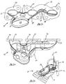
- a first embodiment of the exhaust manifold 10 is designed for connection to one side of a vehicle engine (not shown).
- the manifold 10 has a body 12 comprising a plurality of tubular arms 14 corresponding to the number of exhaust ports. Each of the tubular arms 14 terminates with a mounting flange used to sealingly secure the manifold 10 to the engine in communication with the exhaust port.
- the body 12 including the arms 14 is manufactured of two stamped halves 18 and 20.
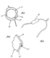
- the stamped metal halves 18 and 20 are attached along a longitudinal weld seam 22.
- the seam 22 has an overlap as best shown in Figure 5 to improve the sealing capability of the seam 22. Additional components such as sensors 24 and heat shields 26 may be incorporated as required for a specific application.
- the manifold 10 formed by the two stamped halves 18 and 20 includes a first tube 14 proximate a collector chamber 28, a second tube 14 remote from the chamber 28 and an intermediate tube 14. All of the tubular arms 14 direct exhaust to the collector chamber 28 which has a larger diameter to accommodate the increased gas volume from all three tubes 14.
- the remote or outermost tube 14 extends substantially parallel to the plane formed by the mounting flanges 16 and includes an upward segment 30 and a downward segment 32 to pass by the intermediate tube 14 such that gases from these two tubes 14 combine into the collector chamber 28.
- the first tube 14 also directs gases to the chamber.
- the collector chamber 28 is oriented substantially downwardly (Fig. 3) to communicate with the exhaust system.
- the first embodiment of the manifold 10 has a collection chamber 28 which is directly in communication with one of the tubes 14.
- the other two exhaust tubes corresponding to the additional exhaust ports converge together prior to communicating with the collector chamber 28.
- the outlet of the collector chamber 28 is disposed at a substantially downward orientation.
- FIG. 7 Alternative embodiments of the stamped manifold are shown in the remaining Figures 7 through 15.
- Each of these manifold configurations is formed of two stamped halves joined along a longitudinal weld seam.
- the stampings incorporate tight curves and specific diameters in order to optimize the flow of exhaust while also facilitating compact installation within the engine compartment.
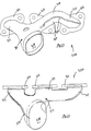
- the second embodiment of Figs. 7 through 9 of the manifold 100 has a different overall configuration to accommodate the exhaust requirements of a different engine setup.
- the exhaust tubes 114 are all in communication prior to directing flow to the exhaust chamber 128 and the remainder of the exhaust system.
- the manifold 100 is constructed from two stamped halves joined at the welded seam 122. The stampings facilitate manufacture of the strict configurations required by modern engine assemblies.
- the third embodiment of the manifold 200 shown in Figures 10 through 12 is the pairwise exhaust manifold of the second embodiment 100 for the opposite side of the engine to collect exhaust and direct the gasses to the exhaust system.
- the manifold 200 similarly includes a pair of stamped halves 218,220 joined along a seam 222.
- the manifold 220 has exhaust tubes 214 to direct flow to the chamber 228.
- the fourth embodiment shown in Figures 13 through 15 is similarly the opposing pair of the manifold 10.
- the manifold 300 includes stamped halves 318,320.
- the weld seam 322 extends along the manifold body to join the halves.
- the manifold 300 has exhaust tubes 314 to direct exhaust flow to a collector chamber 328.
Landscapes
- Engineering & Computer Science (AREA)
- General Engineering & Computer Science (AREA)
- Mechanical Engineering (AREA)
- Chemical & Material Sciences (AREA)
- Combustion & Propulsion (AREA)
- Exhaust Silencers (AREA)
Applications Claiming Priority (2)
| Application Number | Priority Date | Filing Date | Title |
|---|---|---|---|
| US12731399P | 1999-04-01 | 1999-04-01 | |
| US127313P | 1999-04-01 |
Publications (2)
| Publication Number | Publication Date |
|---|---|
| EP1041255A2 true EP1041255A2 (fr) | 2000-10-04 |
| EP1041255A3 EP1041255A3 (fr) | 2003-04-02 |
Family
ID=22429449
Family Applications (1)
| Application Number | Title | Priority Date | Filing Date |
|---|---|---|---|
| EP00106627A Withdrawn EP1041255A3 (fr) | 1999-04-01 | 2000-03-28 | Collecteur d'échappement estampé pour moteurs de véhicule |
Country Status (4)
| Country | Link |
|---|---|
| US (1) | US6651425B2 (fr) |
| EP (1) | EP1041255A3 (fr) |
| CA (1) | CA2303647A1 (fr) |
| MX (1) | MXPA00003281A (fr) |
Cited By (2)
| Publication number | Priority date | Publication date | Assignee | Title |
|---|---|---|---|---|
| CN103895497A (zh) * | 2012-12-27 | 2014-07-02 | 川崎重工业株式会社 | 多用途车辆 |
| DE112006000537B4 (de) * | 2005-03-11 | 2015-03-26 | Faurecia Systemes D'echappement | Auspuffkrümmer für Auspuffgase |
Families Citing this family (7)
| Publication number | Priority date | Publication date | Assignee | Title |
|---|---|---|---|---|
| DE10346552A1 (de) * | 2003-10-07 | 2005-06-30 | Friedrich Boysen Gmbh & Co. Kg | Luftspaltkrümmer |
| FR2867809B1 (fr) * | 2004-03-19 | 2009-05-08 | Renault Sas | Dispositif de protection contre les fuites de gaz d'echappement |
| US7975473B2 (en) * | 2007-10-10 | 2011-07-12 | GM Global Technology Operations LLC | Exhaust manifold assembly |
| US8356411B2 (en) | 2008-04-07 | 2013-01-22 | Benteler Automotive Corporation | Exhaust manifold with hybrid construction and method |
| JP5843830B2 (ja) | 2013-09-18 | 2016-01-13 | アイシン高丘株式会社 | 触媒ケース一体型排気マニホルド |
| WO2019092744A1 (fr) * | 2017-11-09 | 2019-05-16 | Hero MotoCorp Limited | Système d'échappement |
| CN114135380B (zh) * | 2022-01-27 | 2023-01-06 | 潍柴动力股份有限公司 | 一种排气歧管 |
Family Cites Families (18)
| Publication number | Priority date | Publication date | Assignee | Title |
|---|---|---|---|---|
| GB2047227B (en) | 1979-04-02 | 1983-05-25 | Gen Electric | Alumina calcia and baria sealing composition |
| IT1188884B (it) | 1979-09-06 | 1988-01-28 | Zeuna Staerker Kg | Collettore in particolare per un motore a sei cilindri in linea |
| DE8004882U1 (de) * | 1980-02-23 | 1980-06-26 | Friedrich Boysen Gmbh & Co Kg, 7272 Altensteig | Abgaskruemmer fuer die abgasanlage insbesondere eines kraftfahrzeuges |
| DE3216980A1 (de) * | 1982-05-06 | 1983-11-10 | Zeuna-Stärker GmbH & Co KG, 8900 Augsburg | Blechkruemmer fuer verbrennungsmotoren |
| US4671057A (en) | 1985-07-26 | 1987-06-09 | Tecumseh Products Company | Stamped exhaust manifold including a baffle for forming an insulated chamber |
| US4689952A (en) | 1986-06-13 | 1987-09-01 | Arvin Industries, Inc. | Tuned exhaust manifold |
| US4894987A (en) | 1988-08-19 | 1990-01-23 | Ap Parts Manufacturing Company | Stamp formed muffler and catalytic converter assembly |
| US5018661A (en) | 1988-11-25 | 1991-05-28 | Cyb Frederick F | Heat-resistant exhaust manifold and method of preparing same |
| JPH05171932A (ja) | 1991-12-24 | 1993-07-09 | Hino Motors Ltd | 排気マニホルドおよびその製造方法 |
| DE4226715A1 (de) * | 1992-08-12 | 1994-02-17 | Eberspaecher J | Abgaskrümmer |
| US5349817A (en) * | 1993-11-12 | 1994-09-27 | Benteler Industries, Inc. | Air gap manifold port flange connection |
| US5572867A (en) | 1993-11-12 | 1996-11-12 | Benteler Industries, Inc. | Exhaust air rail manifold |
| JP3006394B2 (ja) | 1994-02-10 | 2000-02-07 | トヨタ自動車株式会社 | 内燃機関の排気マニホルド |
| DE19505710C2 (de) | 1994-02-21 | 2002-10-17 | Aisin Takaoka Ltd | Auspuffkrümmer |
| JPH0828262A (ja) | 1994-07-14 | 1996-01-30 | Toyota Motor Corp | 内燃機関の排気系構成部品 |
| US6247552B1 (en) | 1994-12-16 | 2001-06-19 | J. Eberspächer Gmbh & Co. | Air gap-insulated exhaust manifold |
| DE19511514C1 (de) * | 1995-03-29 | 1996-08-01 | Daimler Benz Ag | Abgaskrümmer für eine Brennkraftmaschine |
| JP3741771B2 (ja) * | 1996-04-10 | 2006-02-01 | 株式会社ユタカ技研 | エンジン用マニホールド |
-
2000
- 2000-03-28 EP EP00106627A patent/EP1041255A3/fr not_active Withdrawn
- 2000-03-31 CA CA002303647A patent/CA2303647A1/fr not_active Abandoned
- 2000-04-03 MX MXPA00003281A patent/MXPA00003281A/es unknown
-
2002
- 2002-05-17 US US10/147,791 patent/US6651425B2/en not_active Expired - Fee Related
Non-Patent Citations (1)
| Title |
|---|
| None |
Cited By (2)
| Publication number | Priority date | Publication date | Assignee | Title |
|---|---|---|---|---|
| DE112006000537B4 (de) * | 2005-03-11 | 2015-03-26 | Faurecia Systemes D'echappement | Auspuffkrümmer für Auspuffgase |
| CN103895497A (zh) * | 2012-12-27 | 2014-07-02 | 川崎重工业株式会社 | 多用途车辆 |
Also Published As
| Publication number | Publication date |
|---|---|
| US20020195083A1 (en) | 2002-12-26 |
| MXPA00003281A (es) | 2005-09-15 |
| CA2303647A1 (fr) | 2000-10-01 |
| US6651425B2 (en) | 2003-11-25 |
| EP1041255A3 (fr) | 2003-04-02 |
Similar Documents
| Publication | Publication Date | Title |
|---|---|---|
| US6247552B1 (en) | Air gap-insulated exhaust manifold | |
| EP2324220B1 (fr) | Raccord amélioré entre collecteur d'échappement et boîtier | |
| KR101639345B1 (ko) | 배기가스 터보차저 | |
| US5682741A (en) | Exhaust manifold for an internal combustion engine | |
| US8826660B2 (en) | Exhaust gas system | |
| US6427440B1 (en) | Built-up airgap-insulated exhaust manifold of a motor vehicle and method for producing it | |
| US6604358B2 (en) | Exhaust manifold | |
| US20050183414A1 (en) | Exhaust manifold | |
| US6651425B2 (en) | Stamped exhausts manifold for vehicle engines | |
| US6415889B1 (en) | Stamped-formed muffler apparatus and assembly process | |
| KR20140036008A (ko) | 자동차용 모듈형 매니폴드 | |
| US8656709B2 (en) | Dual-layer to flange welded joint | |
| KR20050033843A (ko) | 에어-갭 매니폴드 | |
| US8215447B1 (en) | Exhaust device of vehicle and straddle-type four-wheeled vehicle provided with the same | |
| US6619426B2 (en) | Exhaust silencer | |
| US20080053079A1 (en) | Housing for an Exhaust Gas Purification Component for Forming a Joined Connection with an Exhaust Line Section, Exhaust System Having the Housing and Motor Vehicle Having the Exhaust System | |
| US7228890B2 (en) | Heat exchanger with integral shell and tube plates | |
| US20070180820A1 (en) | Dual wall exhaust manifold and method of making same | |
| US20040040549A1 (en) | Dual seal EGR tube assembly | |
| US4215742A (en) | Exhaust coolers | |
| US20020116819A1 (en) | Method of making an exhaust gas collector | |
| TW491928B (en) | Intake manifold | |
| JP2001317351A (ja) | 排気マニホルド | |
| US6050362A (en) | Exhaust system with seamed roll joints and method for manufacture | |
| JPS5898620A (ja) | 内燃機関の排気浄化装置 |
Legal Events
| Date | Code | Title | Description |
|---|---|---|---|
| PUAI | Public reference made under article 153(3) epc to a published international application that has entered the european phase |
Free format text: ORIGINAL CODE: 0009012 |
|
| AK | Designated contracting states |
Kind code of ref document: A2 Designated state(s): AT BE CH CY DE DK ES FI FR GB GR IE IT LI LU MC NL PT SE |
|
| AX | Request for extension of the european patent |
Free format text: AL;LT;LV;MK;RO;SI |
|
| PUAL | Search report despatched |
Free format text: ORIGINAL CODE: 0009013 |
|
| AK | Designated contracting states |
Kind code of ref document: A3 Designated state(s): AT BE CH CY DE DK ES FI FR GB GR IE IT LI LU MC NL PT SE Designated state(s): AT BE CH CY DE DK ES FI FR GB GR IE IT LI LU MC NL PT SE |
|
| AX | Request for extension of the european patent |
Extension state: AL LT LV MK RO SI |
|
| AKX | Designation fees paid | ||
| REG | Reference to a national code |
Ref country code: DE Ref legal event code: 8566 |
|
| STAA | Information on the status of an ep patent application or granted ep patent |
Free format text: STATUS: THE APPLICATION IS DEEMED TO BE WITHDRAWN |
|
| 18D | Application deemed to be withdrawn |
Effective date: 20031003 |