EP1041267A2 - Carburateur avec valve d'étranglement d'air et de mélange pour moteur à deux temps - Google Patents
Carburateur avec valve d'étranglement d'air et de mélange pour moteur à deux temps Download PDFInfo
- Publication number
- EP1041267A2 EP1041267A2 EP00106707A EP00106707A EP1041267A2 EP 1041267 A2 EP1041267 A2 EP 1041267A2 EP 00106707 A EP00106707 A EP 00106707A EP 00106707 A EP00106707 A EP 00106707A EP 1041267 A2 EP1041267 A2 EP 1041267A2
- Authority
- EP
- European Patent Office
- Prior art keywords
- air
- throttle valve
- valve
- carburetor
- gear
- Prior art date
- Legal status (The legal status is an assumption and is not a legal conclusion. Google has not performed a legal analysis and makes no representation as to the accuracy of the status listed.)
- Granted
Links
- 239000000446 fuel Substances 0.000 claims abstract description 53
- 230000008878 coupling Effects 0.000 claims abstract description 6
- 238000010168 coupling process Methods 0.000 claims abstract description 6
- 238000005859 coupling reaction Methods 0.000 claims abstract description 6
- 206010044048 Tooth missing Diseases 0.000 claims description 3
- ZPUCINDJVBIVPJ-LJISPDSOSA-N cocaine Chemical compound O([C@H]1C[C@@H]2CC[C@@H](N2C)[C@H]1C(=O)OC)C(=O)C1=CC=CC=C1 ZPUCINDJVBIVPJ-LJISPDSOSA-N 0.000 claims 1
- 239000000203 mixture Substances 0.000 abstract description 23
- 230000002000 scavenging effect Effects 0.000 abstract description 21
- 238000002485 combustion reaction Methods 0.000 abstract description 16
- 239000012530 fluid Substances 0.000 abstract description 6
- 239000004215 Carbon black (E152) Substances 0.000 description 3
- 239000007789 gas Substances 0.000 description 3
- 229930195733 hydrocarbon Natural products 0.000 description 3
- 150000002430 hydrocarbons Chemical class 0.000 description 3
- 238000004519 manufacturing process Methods 0.000 description 3
- 230000001133 acceleration Effects 0.000 description 1
- 239000000567 combustion gas Substances 0.000 description 1
- 230000006835 compression Effects 0.000 description 1
- 238000007906 compression Methods 0.000 description 1
- 230000001934 delay Effects 0.000 description 1
- 239000002828 fuel tank Substances 0.000 description 1
- 239000012528 membrane Substances 0.000 description 1
Images

Classifications
-
- F—MECHANICAL ENGINEERING; LIGHTING; HEATING; WEAPONS; BLASTING
- F02—COMBUSTION ENGINES; HOT-GAS OR COMBUSTION-PRODUCT ENGINE PLANTS
- F02B—INTERNAL-COMBUSTION PISTON ENGINES; COMBUSTION ENGINES IN GENERAL
- F02B25/00—Engines characterised by using fresh charge for scavenging cylinders
- F02B25/20—Means for reducing the mixing of charge and combustion residues or for preventing escape of fresh charge through outlet ports not provided for in, or of interest apart from, subgroups F02B25/02 - F02B25/18
- F02B25/22—Means for reducing the mixing of charge and combustion residues or for preventing escape of fresh charge through outlet ports not provided for in, or of interest apart from, subgroups F02B25/02 - F02B25/18 by forming air cushion between charge and combustion residues
-
- F—MECHANICAL ENGINEERING; LIGHTING; HEATING; WEAPONS; BLASTING
- F02—COMBUSTION ENGINES; HOT-GAS OR COMBUSTION-PRODUCT ENGINE PLANTS
- F02M—SUPPLYING COMBUSTION ENGINES IN GENERAL WITH COMBUSTIBLE MIXTURES OR CONSTITUENTS THEREOF
- F02M11/00—Multi-stage carburettors, Register-type carburettors, i.e. with slidable or rotatable throttling valves in which a plurality of fuel nozzles, other than only an idling nozzle and a main one, are sequentially exposed to air stream by throttling valve
- F02M11/10—Register carburettors with rotatable throttling valves
-
- F—MECHANICAL ENGINEERING; LIGHTING; HEATING; WEAPONS; BLASTING
- F02—COMBUSTION ENGINES; HOT-GAS OR COMBUSTION-PRODUCT ENGINE PLANTS
- F02M—SUPPLYING COMBUSTION ENGINES IN GENERAL WITH COMBUSTIBLE MIXTURES OR CONSTITUENTS THEREOF
- F02M23/00—Apparatus for adding secondary air to fuel-air mixture
- F02M23/02—Apparatus for adding secondary air to fuel-air mixture with personal control, or with secondary-air valve controlled by main combustion-air throttle
- F02M23/03—Apparatus for adding secondary air to fuel-air mixture with personal control, or with secondary-air valve controlled by main combustion-air throttle the secondary air-valve controlled by main combustion-air throttle
-
- Y—GENERAL TAGGING OF NEW TECHNOLOGICAL DEVELOPMENTS; GENERAL TAGGING OF CROSS-SECTIONAL TECHNOLOGIES SPANNING OVER SEVERAL SECTIONS OF THE IPC; TECHNICAL SUBJECTS COVERED BY FORMER USPC CROSS-REFERENCE ART COLLECTIONS [XRACs] AND DIGESTS
- Y02—TECHNOLOGIES OR APPLICATIONS FOR MITIGATION OR ADAPTATION AGAINST CLIMATE CHANGE
- Y02T—CLIMATE CHANGE MITIGATION TECHNOLOGIES RELATED TO TRANSPORTATION
- Y02T10/00—Road transport of goods or passengers
- Y02T10/10—Internal combustion engine [ICE] based vehicles
- Y02T10/12—Improving ICE efficiencies
-
- Y—GENERAL TAGGING OF NEW TECHNOLOGICAL DEVELOPMENTS; GENERAL TAGGING OF CROSS-SECTIONAL TECHNOLOGIES SPANNING OVER SEVERAL SECTIONS OF THE IPC; TECHNICAL SUBJECTS COVERED BY FORMER USPC CROSS-REFERENCE ART COLLECTIONS [XRACs] AND DIGESTS
- Y10—TECHNICAL SUBJECTS COVERED BY FORMER USPC
- Y10S—TECHNICAL SUBJECTS COVERED BY FORMER USPC CROSS-REFERENCE ART COLLECTIONS [XRACs] AND DIGESTS
- Y10S261/00—Gas and liquid contact apparatus
- Y10S261/01—Auxiliary air inlet carburetors
Definitions
- This invention relates to a carburetor for a two stroke engine and more particularly to a carburetor which provides a scavenging air supply independently of a fuel and air mixture.
- a fuel and air mixture is supplied to the engine crankcase through a fuel and air mixing passage in the carburetor.
- the fuel and air mixture in the crankcase is pressurized in the crankcase during a portion of the stroke of a piston of the engine and is supplied through a scavenging or transfer port to a combustion chamber of the engine cylinder to assist the scavenging of combustion gases which remain in the cylinder and to provide a fresh fuel and air mixture for the next combustion event.
- a portion of the fresh fuel and air mixture provided to the combustion chamber escapes through the exhaust port with the exhaust gas thereby increasing the hydrocarbon content of the engine emissions and reducing the fuel efficiency of the engine.
- a throttle valve may be used to control fluid flow through the fuel and air mixture passage and an air valve to control the scavenging air flow through the second bore.
- An example of a conventional carburetor having the throttle valve and air valve provided in a carburetor body is shown in Japanese Patent No. 9,268,918
- the scavenging air supply is undesirable as it provides too much air to the engine causing an undesirably lean fuel and air mixture in the engine and poor engine performance, stability and acceleration. Therefore, selective control of the scavenging air supply relative to the fuel and air mixture supply, is needed.
- the throttle valve and the air valve are barrel type valves formed integrally with each other, in order to control the opening time of the air valve relative to the throttle valve, the throttle valve and the air valve must have different diameters or there must be a difference in the extent to which the valves open. Forming the valves of different diameter increases the cost to make the valves and the cost to manufacture the carburetor to accommodate the differently sized valves.
- a carburetor for providing a fuel and air mixture and a scavenging air supply to a two stroke internal combustion engine has a throttle valve received in a fuel and air mixing passage and connected to a throttle drive for controlling engine operation and an air valve received in an air passage and selectively operably connected to the throttle valve by a lost motion coupling.
- the throttle valve and the air valve are barrel-type valves each comprising an opening formed through a shaft extending transversely through and rotatable within an associated bore of the carburetor body.
- the lost motion coupling may comprise a pair of selectively meshed gears consisting of a first partial gear connected to a shaft of the throttle valve for co-rotation with the throttle valve shaft, and a second partial gear connected to a shaft of the air valve for co-rotation with the air valve shaft.
- a gear ratio of the gear pair is set in such a manner that the first partial gear does not mesh with the second partial gear until the throttle valve has rotated to a predetermined angle or partially open position from an idle position and the throttle valve and the air valve are simultaneously operable at a fully opened position to permit substantially unrestricted fluid flow through their respective passages in the carburetor body.
- a throttle valve lever is rotated against a spring biasing it to its idle position by means of an operating lever through a remote cable, to further open the throttle valve from its idle position towards its wide open position.
- the first partial gear when the first partial gear has rotated a predetermined angle, the first partial gear abuts against or initially meshes with the second partial gear which is connected to a shaft of the air valve and continued opening of the throttle valve causes the first partial gear to drive the second partial gear for rotation. This rotation of the second partial gear rotates the air valve from its fully closed position toward its fully open position.
- the first partial gear continues to rotate the second partial gear to increase the opening degree of the air valve until it reaches its fully opened position preferably at the same time the throttle valve reaches its wide open position.
- the throttle valve and the air valve can be simultaneously opened, by providing the throttle valve and the air valve as separate members connected to the gears which have different outer diameters, and by selecting shapes and numbers of teeth of the gears, and determining an appropriate gear ratio.
- Objects, features and advantages of the invention include providing a carburetor for supplying a fuel and air mixture to an engine and selectively supplying a scavenging air supply to the engine which terminates the scavenging air supply at low speed and low load engine operation, permits timing of the initial opening of the air valve relative to the throttle valve of the carburetor to be freely set, selectively interconnects the throttle valve and air valve, permits at least some relative movement between the throttle valve and air valve, may have a throttle valve and an air valve which need not be different from each other in diameter or in the degree or extent to which they open in order to retard the opening time of the air valve and inhibit or prevent providing the scavenging air supply at least at engine idle operation, does not interconnect the throttle valve and air valve with a lever and link arrangement, avoids providing too much air to the engine, improves engine operation, reduces engine emissions, increases engine fuel efficiency, is of relatively simple design and economical manufacture and assembly, reliable and in service has a long useful life.
- FIGS. 1 and 2 illustrate a carburetor 10 for a two-stroke internal combustion engine which is constructed to selectively deliver to the engine a scavenging air supply through an air passage 16 independently of a fuel and air mixture provided to the engine through a fuel and air mixing passage 12.
- the carburetor 10 has a body 11 in which the air passage 16 and the fuel and air mixing passage 12 are formed.
- a barrel type throttle valve 20 has a shaft 24 which extends through a cylindrical bore 14 generally transversely through the fuel and air mixing passage 12 and has a throttle bore 22 therethrough.
- the throttle valve shaft 24 is connected to a throttle lever (not shown) which is actuated to control the movement of the throttle valve 20 and hence, the operation of the engine between idle and wide open throttle engine operating conditions.
- a barrel type air valve 30 has a shaft 34 which extends through another cylindrical bore 18 generally transversely through the air passage 16 and has an air bore 32 therethrough.
- the throttle valve shaft 24 and air valve shaft 34 are each rotatable within their bores 14,18 on an axis generally transverse to their respective passages 12,16 and parallel to each other to control the extent to which the throttle bore 22 and the air bore 32 are aligned with their respective passages 12,16 to control the fluid flow through the passages 12,16.
- the carburetor body 11 includes in its lower part a constant pressure fuel chamber and an atmospheric chamber which are partitioned by means of a membrane or diaphragm.
- the constant pressure fuel chamber is supplied with fuel from a fuel tank by a fuel pump and is maintained at a predetermined pressure.
- a fuel nozzle 26 projects from the fuel chamber into the throttle bore 22 of the throttle valve 20.
- a rod valve 27 (FIG. 2) projecting into the throttle bore 22 is inserted into the fuel nozzle 26 so as to adjust the extent to which a fuel jet port 26a of the fuel nozzle 26 is open.
- the throttle valve lever By rotating the throttle valve lever against a force of a return spring which biases the throttle valve lever and hence, the throttle valve 20, to their idle positions, the extent to which the throttle valve 20 is open is increased.
- the rod valve 27 is moved axially relative to the fuel nozzle 26 by means of a cam mechanism which is formed between the throttle valve lever and an upper end wall of the carburetor body to increase the degree to which the fuel jet port 26a of the fuel nozzle 26 is opened. This permits a greater volume of fuel to flow through the fuel jet port 26a as the engine accelerates from idle towards wide open throttle operation and hence, requires more fuel for its operation.
- the throttle valve 20 is yieldably rotationally biased to its idle position and the air valve 30 is also yieldably rotationally biased to its fully closed position by separate return springs (not shown).
- the throttle bore 22 is only slightly open to the air intake passage 12, and a mixture of air drawn through the fuel and air mixing passage 12 and fuel from the fuel nozzle 26 is supplied to a crankcase of the engine.
- the air bore 32 of the air valve 30 is rotated completely out of registry with the air passage 16 to prevent fluid flow past the air valve 30 so that scavenging air will not be supplied to the cylinder of the engine.
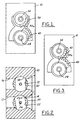
- a first partial gear 40 is connected to the throttle valve shaft 24 for co-movement therewith.
- a second partial gear 50 is connected to the air valve shaft 34 and is engageable with the first partial gear 40 during at least a portion of the throttle valve 20 movement from its idle position to its wide open position to drive the second partial gear 50 and hence, the air valve 30 for rotation.
- the second partial gear 50 has a tooth missing from its profile providing a gap 50a between its first and second teeth so that in its idle position and upon initial rotation of the throttle valve 20 from its idle position, a first tooth of the first partial gear 40 does not engage the second partial gear 50.
- the first partial gear 40 does not engage the second partial gear 50 until the throttle valve 20 is opened or rotated a predetermined amount from its idle position.
- the throttle valve 20 is opened further than at the idle position ( FIG. 2), and a greater amount of the fuel and air mixture than at the idle position is supplied to the engine.
- the air valve 30 remains in its fully closed position preventing communication between the air bore 32 and the air passage 16, and a scavenging air supply is not provided to the engine.
- the first partial gear 40 is in contact with the second partial gear 50 but has not begun to rotate the second partial gear 50.
- the first partial gear 40 of the throttle valve 20 has rotated away from its idle position by a predetermined angle, it comes into contact with the second partial gear 50 of the air valve 30. Further rotation of the first partial gear 40 beyond the predetermined angle at which the gears 40,50 initially engage or mesh, rotates the second partial gear 50 and hence, rotates the air valve 30 to open it.
- the throttle valve 20 is fully opened, and a larger amount of the fuel and air mixture than at the lower speed operation is supplied to the engine.
- the air valve 30 is also fully opened to supply scavenging air from the air passage 16 to the cylinder of the engine.
- the first partial gear 40 causes the second partial gear 50 to rotate from the position as shown in FIG. 3 to the position as shown in FIG. 5 along with the rotation of the first partial gear 40.
- the throttle valve 20 rotates from its low speed position shown in FIG. 4 to its high speed or wide open position shown in FIG. 6 permitting substantially unrestricted fluid flow through the throttle valve 20.
- the first partial gear 40 connected to the throttle valve shaft 24 rotates from its low speed position shown in FIG. 3 to its high speed position shown in FIG. 5 to likewise rotate the second partial gear 50.
- the air valve 30 is rotated from its fully closed position shown in FIG. 4 to its fully open position shown in FIG. 6 permitting a substantially unrestricted air flow through the air passage 16.
- the fuel and air mixture is supplied to the engine according to the degree to which the throttle valve 20 is opened, and simultaneously air is supplied to the cylinder according to the degree to which the air valve 30 is opened.
- the scavenging air supply is first introduced to the combustion chamber to facilitate the removal of exhaust gases from the combustion chamber. Then the fuel and air mixture is supplied to the combustion chamber and the scavenging air and the fuel and air mixture are in a layered or stratified state in the combustion chamber to inhibit the escape through an exhaust port of the fresh fuel and air mixture. This greatly reduces the hydrocarbon content of the engine emissions, improves fuel efficiency, and improves stability and performance of the engine.
- the carburetor constructed as above described, there is no need to make the throttle valve 20 and the air valve 30 different in diameter or in the degree to which they are opened to retard or delay the opening of the air valve 30 relative to the opening of the throttle valve 20.
- the throttle valve 20 and the air valve 30 can be moved to their fully or wide open positions simultaneously which is desirable to support wide open throttle operation of the engine.
- the outer diameters of the throttle valve 20 and the air valve 30 can be as small as possible and may be equal to each other to facilitate manufacturing the valves and the carburetor to receive the valves.
- the second partial gear may have a tooth missing from its profile or may otherwise have a gap which delays initial meshing or engagement of the gears 40,50.
- the rate at which the air valve 30 and throttle valve 20 open may be varied and controlled by selecting the relative size of the gears 40,50, and by selecting shapes and numbers of teeth of the gears, and determining an appropriate gear ratio.
Landscapes
- Engineering & Computer Science (AREA)
- Chemical & Material Sciences (AREA)
- Combustion & Propulsion (AREA)
- Mechanical Engineering (AREA)
- General Engineering & Computer Science (AREA)
- Control Of Throttle Valves Provided In The Intake System Or In The Exhaust System (AREA)
Applications Claiming Priority (2)
| Application Number | Priority Date | Filing Date | Title |
|---|---|---|---|
| JP11086971A JP2000282874A (ja) | 1999-03-29 | 1999-03-29 | 絞り弁と空気弁を備えた2行程内燃機関用気化器 |
| JP8697199 | 1999-03-29 |
Publications (3)
| Publication Number | Publication Date |
|---|---|
| EP1041267A2 true EP1041267A2 (fr) | 2000-10-04 |
| EP1041267A3 EP1041267A3 (fr) | 2001-03-21 |
| EP1041267B1 EP1041267B1 (fr) | 2005-03-02 |
Family
ID=13901772
Family Applications (1)
| Application Number | Title | Priority Date | Filing Date |
|---|---|---|---|
| EP00106707A Expired - Lifetime EP1041267B1 (fr) | 1999-03-29 | 2000-03-29 | Carburateur avec valve d'étranglement d'air et de mélange pour moteur à deux temps |
Country Status (4)
| Country | Link |
|---|---|
| US (1) | US6347787B1 (fr) |
| EP (1) | EP1041267B1 (fr) |
| JP (1) | JP2000282874A (fr) |
| DE (1) | DE60018317D1 (fr) |
Cited By (6)
| Publication number | Priority date | Publication date | Assignee | Title |
|---|---|---|---|---|
| EP1378653A3 (fr) * | 2002-07-03 | 2004-01-14 | Walbro Japan, Inc. | Mécanisme à charge stratifiée de moteur à deux temps |
| WO2005124120A1 (fr) * | 2004-06-15 | 2005-12-29 | Husqvarna Ab | Systeme de moteur a combustion a deux temps enferme dans un carter |
| EP1559899A3 (fr) * | 2003-12-03 | 2006-07-05 | Electrolux Home Products, Inc. | Mécanisme de soupape d'air pour moteur à deux temps |
| US7389754B2 (en) | 2004-06-15 | 2008-06-24 | Husqvarna Ab | System for a two-stroke crankcase scavenged combustion engine |
| CN101131136B (zh) * | 2006-08-17 | 2011-03-30 | 沃尔布罗发动机使用有限责任公司 | 分层扫气化油器 |
| EP1712762A4 (fr) * | 2003-11-12 | 2011-06-22 | Husqvarna Zenoah Co Ltd | Mecanisme de conduction et de couplage |
Families Citing this family (12)
| Publication number | Priority date | Publication date | Assignee | Title |
|---|---|---|---|---|
| US6591794B2 (en) | 2000-10-24 | 2003-07-15 | Zama Japan | Air-fuel ratio control system for a stratified scavenging two-cycle engine |
| US7007931B2 (en) * | 2002-06-03 | 2006-03-07 | Walbro Japan, Inc. | Rotary throttle valve carburetor |
| US6708958B1 (en) | 2002-10-04 | 2004-03-23 | Electrolux Home Products, Inc. | Air valve mechanism for two-cycle engine |
| US7104526B2 (en) * | 2003-06-10 | 2006-09-12 | Homelite Technologies, Ltd. | Carburetor with intermediate throttle valve blocking position |
| JP4061252B2 (ja) * | 2003-08-11 | 2008-03-12 | ザマ・ジャパン株式会社 | 2サイクルエンジン用気化器 |
| SE0302439D0 (sv) * | 2003-09-12 | 2003-09-12 | Electrolux Ab | Throttle control device for a hand held tool |
| JP4286636B2 (ja) | 2003-11-12 | 2009-07-01 | ハスクバーナ・ゼノア株式会社 | 角度を成す弁軸間の伝導結合機構 |
| US7104253B1 (en) | 2005-03-30 | 2006-09-12 | Walbro Engine Management, L.L.C. | Stratified scavenging carburetor |
| US7543563B2 (en) * | 2007-03-23 | 2009-06-09 | Honda Motor Co., Ltd. | High flow dual throttle body for small displacement engines |
| US8042514B2 (en) * | 2008-07-24 | 2011-10-25 | Honda Motor Company, Ltd. | Throttle bodies and saddle-type vehicles including valved intake conduits for engine |
| US8453998B2 (en) * | 2010-08-17 | 2013-06-04 | Walbro Engine Management, L.L.C. | Air scavenging carburetor |
| US9915221B2 (en) * | 2015-11-25 | 2018-03-13 | GM Global Technology Operations LLC | System and method for engine combustion |
Citations (1)
| Publication number | Priority date | Publication date | Assignee | Title |
|---|---|---|---|---|
| JPH09268918A (ja) | 1996-04-03 | 1997-10-14 | Komatsu Zenoah Co | 2行程内燃機関用気化器 |
Family Cites Families (22)
| Publication number | Priority date | Publication date | Assignee | Title |
|---|---|---|---|---|
| DE342274C (de) | 1916-12-01 | 1921-10-15 | Wilhelm Kieffer | Einrichtung zum Nachvergasen von Vergaser-Brennstoffluftgemischen |
| DE432953C (de) | 1924-02-01 | 1926-08-18 | Stromberg Motor Devices Compan | Drosselanordnung fuer Spritzvergaser |
| US2325010A (en) | 1941-06-14 | 1943-07-20 | William E Abbas | Carburetor |
| US3174469A (en) * | 1960-04-09 | 1965-03-23 | Cvjetko Galic | Carburetor arrangement |
| FR1505407A (fr) | 1966-08-02 | 1967-12-15 | Zenith Carburateur Soc Du | Dispositif de carburation pour l'alimentation des moteurs à combustion interne |
| DE2204192C3 (de) | 1972-01-29 | 1979-03-22 | Robert Bosch Gmbh, 7000 Stuttgart | Vorrichtung zur Verbesserung der Abgase einer Vergaser-Brennkraftmaschine |
| JPS5154133A (en) | 1974-11-06 | 1976-05-13 | Honda Motor Co Ltd | Kikakino chookubenseigyosochi |
| US4182295A (en) | 1975-07-01 | 1980-01-08 | Robert Bosch Gmbh | Method and apparatus for engine fuel control |
| JPS5266119A (en) | 1975-11-28 | 1977-06-01 | Hitachi Ltd | Duplex carburetor |
| US4073278A (en) | 1976-01-16 | 1978-02-14 | Glenn Edward R | Carburator |
| DD135833B1 (de) | 1978-04-19 | 1980-07-23 | Morgenstern Carl Hans | Verfahren und vorrichtung fuer eine ladungsschichtung bei zweitakt-ottomotoren |
| JPS54140016A (en) * | 1978-04-21 | 1979-10-30 | Toyota Motor Corp | Suction device of multicylinder internal combusion engine |
| US4333429A (en) | 1978-06-15 | 1982-06-08 | Honda Giken Kogyo Kabushiki Kaisha | Internal combustion engine |
| JPS5510014A (en) | 1978-07-06 | 1980-01-24 | Toyota Motor Corp | Division-operation controlled multi-cylinder internal combustion engine |
| JPS57183520A (en) | 1981-05-06 | 1982-11-11 | Isao Oda | Device for preventing mixture from blowing through two-cycle engine |
| AT394755B (de) | 1986-07-08 | 1992-06-25 | Bombardier Rotax Gmbh | Zweitakt-brennkraftmaschine mit einer kurbelkastenspuelung |
| US4796579A (en) | 1988-03-02 | 1989-01-10 | Ford Motor Company | Automotive type throttle body |
| DE3909570A1 (de) | 1989-03-23 | 1990-09-27 | Vdo Schindling | Lastverstelleinrichtung |
| DE4117554B4 (de) | 1991-05-29 | 2004-05-27 | Walbro Gmbh | Vergaser für eine Brennkraftmaschine, insbesondere einer Motorsäge |
| IT1272718B (it) | 1993-10-01 | 1997-06-26 | Piaggio Veicoli Europ | Dispositivo di preparazione della miscela per motori a doppia alimentazione |
| JP3024072B2 (ja) | 1996-10-17 | 2000-03-21 | 財団法人石油産業活性化センター | 層状掃気2サイクルエンジン |
| US6000683A (en) | 1997-11-26 | 1999-12-14 | Walbro Corporation | Carburetor throttle and choke control mechanism |
-
1999
- 1999-03-29 JP JP11086971A patent/JP2000282874A/ja not_active Withdrawn
-
2000
- 2000-03-21 US US09/531,711 patent/US6347787B1/en not_active Expired - Fee Related
- 2000-03-29 DE DE60018317T patent/DE60018317D1/de not_active Expired - Fee Related
- 2000-03-29 EP EP00106707A patent/EP1041267B1/fr not_active Expired - Lifetime
Patent Citations (1)
| Publication number | Priority date | Publication date | Assignee | Title |
|---|---|---|---|---|
| JPH09268918A (ja) | 1996-04-03 | 1997-10-14 | Komatsu Zenoah Co | 2行程内燃機関用気化器 |
Cited By (7)
| Publication number | Priority date | Publication date | Assignee | Title |
|---|---|---|---|---|
| EP1378653A3 (fr) * | 2002-07-03 | 2004-01-14 | Walbro Japan, Inc. | Mécanisme à charge stratifiée de moteur à deux temps |
| US6928996B2 (en) | 2002-07-03 | 2005-08-16 | Walbro Japan, Inc. | Stratified scavenging mechanism of a two-stroke engine |
| EP1712762A4 (fr) * | 2003-11-12 | 2011-06-22 | Husqvarna Zenoah Co Ltd | Mecanisme de conduction et de couplage |
| EP1559899A3 (fr) * | 2003-12-03 | 2006-07-05 | Electrolux Home Products, Inc. | Mécanisme de soupape d'air pour moteur à deux temps |
| WO2005124120A1 (fr) * | 2004-06-15 | 2005-12-29 | Husqvarna Ab | Systeme de moteur a combustion a deux temps enferme dans un carter |
| US7389754B2 (en) | 2004-06-15 | 2008-06-24 | Husqvarna Ab | System for a two-stroke crankcase scavenged combustion engine |
| CN101131136B (zh) * | 2006-08-17 | 2011-03-30 | 沃尔布罗发动机使用有限责任公司 | 分层扫气化油器 |
Also Published As
| Publication number | Publication date |
|---|---|
| DE60018317D1 (de) | 2005-04-07 |
| US6347787B1 (en) | 2002-02-19 |
| EP1041267B1 (fr) | 2005-03-02 |
| JP2000282874A (ja) | 2000-10-10 |
| EP1041267A3 (fr) | 2001-03-21 |
Similar Documents
| Publication | Publication Date | Title |
|---|---|---|
| US6347787B1 (en) | Carburetor with air and throttle valve for two-cycle engine | |
| EP1026390B1 (fr) | Carburateur pour moteur à deux temps | |
| US5062396A (en) | Device and method for introducing a carburetted mixture under presssure into the cylinder of an engine | |
| JP3768590B2 (ja) | 2行程内燃機関用気化器 | |
| JP2000097130A (ja) | 燃料噴射式エンジン用の燃料及び空気送給装置 | |
| US7377496B2 (en) | Carburetor for two-cycle engine | |
| JPH09268917A (ja) | 2行程内燃機関用気化器 | |
| US5140952A (en) | Method of and apparatus for improving the operation of an engine | |
| US6189495B1 (en) | Direct cylinder fuel injection | |
| CN100447389C (zh) | 传动和连接机构 | |
| CN1993544B (zh) | 具有受控的附加空气的二冲程内燃机系统 | |
| US20070057386A1 (en) | Carburetor for stratified scavenging two-cycle engine | |
| JPH0270917A (ja) | 2サイクルエンジン | |
| JPS6176716A (ja) | 横置き型2サイクル内燃機関 | |
| US5351660A (en) | Electrically activated dynamic valve for spark ignition engines | |
| US7673617B2 (en) | Indirect-injection internal-combustion engine, notably spark-ignition supercharged engine, with two intake means for carrying out a burnt gas scavenging stage | |
| US6467455B1 (en) | Four-stroke internal combustion engine | |
| JP3031533B2 (ja) | 2行程内燃機関用気化器 | |
| JP2656181B2 (ja) | 二元燃料エンジン | |
| JP3562609B2 (ja) | 火花点火式2サイクル内燃機関の燃焼制御装置 | |
| CN100523473C (zh) | 汽化器和气阀组件及使用该组件的两冲程内燃机系统 | |
| JP2001295651A (ja) | 層状掃気2サイクルエンジン | |
| JPH0598994A (ja) | 二元燃料エンジン | |
| JPH05302521A (ja) | 2サイクルエンジンの掃気装置 | |
| US7287495B1 (en) | Two-cycle engine |
Legal Events
| Date | Code | Title | Description |
|---|---|---|---|
| PUAI | Public reference made under article 153(3) epc to a published international application that has entered the european phase |
Free format text: ORIGINAL CODE: 0009012 |
|
| AK | Designated contracting states |
Kind code of ref document: A2 Designated state(s): AT BE CH CY DE DK ES FI FR GB GR IE IT LI LU MC NL PT SE |
|
| AX | Request for extension of the european patent |
Free format text: AL;LT;LV;MK;RO;SI |
|
| PUAL | Search report despatched |
Free format text: ORIGINAL CODE: 0009013 |
|
| AK | Designated contracting states |
Kind code of ref document: A3 Designated state(s): AT BE CH CY DE DK ES FI FR GB GR IE IT LI LU MC NL PT SE |
|
| AX | Request for extension of the european patent |
Free format text: AL;LT;LV;MK;RO;SI |
|
| 17P | Request for examination filed |
Effective date: 20010706 |
|
| AKX | Designation fees paid |
Free format text: DE IT SE |
|
| 17Q | First examination report despatched |
Effective date: 20030902 |
|
| GRAP | Despatch of communication of intention to grant a patent |
Free format text: ORIGINAL CODE: EPIDOSNIGR1 |
|
| GRAS | Grant fee paid |
Free format text: ORIGINAL CODE: EPIDOSNIGR3 |
|
| GRAA | (expected) grant |
Free format text: ORIGINAL CODE: 0009210 |
|
| AK | Designated contracting states |
Kind code of ref document: B1 Designated state(s): DE IT SE |
|
| PG25 | Lapsed in a contracting state [announced via postgrant information from national office to epo] |
Ref country code: IT Free format text: LAPSE BECAUSE OF FAILURE TO SUBMIT A TRANSLATION OF THE DESCRIPTION OR TO PAY THE FEE WITHIN THE PRE;WARNING: LAPSES OF ITALIAN PATENTS WITH EFFECTIVE DATE BEFORE 2007 MAY HAVE OCCURRED AT ANY TIME BEFORE 2007. THE CORRECT EFFECTIVE DATE MAY BE DIFFERENT FROM THE ONE RECORDED.SCRIBED TIME-LIMIT Effective date: 20050302 |
|
| REF | Corresponds to: |
Ref document number: 60018317 Country of ref document: DE Date of ref document: 20050407 Kind code of ref document: P |
|
| PG25 | Lapsed in a contracting state [announced via postgrant information from national office to epo] |
Ref country code: DE Free format text: LAPSE BECAUSE OF NON-PAYMENT OF DUE FEES Effective date: 20051001 |
|
| PLBE | No opposition filed within time limit |
Free format text: ORIGINAL CODE: 0009261 |
|
| STAA | Information on the status of an ep patent application or granted ep patent |
Free format text: STATUS: NO OPPOSITION FILED WITHIN TIME LIMIT |
|
| 26N | No opposition filed |
Effective date: 20051205 |
|
| PG25 | Lapsed in a contracting state [announced via postgrant information from national office to epo] |
Ref country code: SE Free format text: LAPSE BECAUSE OF FAILURE TO SUBMIT A TRANSLATION OF THE DESCRIPTION OR TO PAY THE FEE WITHIN THE PRESCRIBED TIME-LIMIT Effective date: 20050602 |