EP1041380A2 - Capteur d'hydrocarbone et méthode pour sa production - Google Patents
Capteur d'hydrocarbone et méthode pour sa production Download PDFInfo
- Publication number
- EP1041380A2 EP1041380A2 EP00106922A EP00106922A EP1041380A2 EP 1041380 A2 EP1041380 A2 EP 1041380A2 EP 00106922 A EP00106922 A EP 00106922A EP 00106922 A EP00106922 A EP 00106922A EP 1041380 A2 EP1041380 A2 EP 1041380A2
- Authority
- EP
- European Patent Office
- Prior art keywords
- cathode
- layer
- hydrocarbon
- hydrocarbon sensor
- sensor according
- Prior art date
- Legal status (The legal status is an assumption and is not a legal conclusion. Google has not performed a legal analysis and makes no representation as to the accuracy of the status listed.)
- Granted
Links
Images





Classifications
-
- G—PHYSICS
- G01—MEASURING; TESTING
- G01N—INVESTIGATING OR ANALYSING MATERIALS BY DETERMINING THEIR CHEMICAL OR PHYSICAL PROPERTIES
- G01N33/00—Investigating or analysing materials by specific methods not covered by groups G01N1/00 - G01N31/00
- G01N33/0004—Gaseous mixtures, e.g. polluted air
- G01N33/0009—General constructional details of gas analysers, e.g. portable test equipment
- G01N33/0027—General constructional details of gas analysers, e.g. portable test equipment concerning the detector
- G01N33/0036—General constructional details of gas analysers, e.g. portable test equipment concerning the detector specially adapted to detect a particular component
- G01N33/0047—Organic compounds
-
- G—PHYSICS
- G01—MEASURING; TESTING
- G01N—INVESTIGATING OR ANALYSING MATERIALS BY DETERMINING THEIR CHEMICAL OR PHYSICAL PROPERTIES
- G01N27/00—Investigating or analysing materials by the use of electric, electrochemical, or magnetic means
- G01N27/26—Investigating or analysing materials by the use of electric, electrochemical, or magnetic means by investigating electrochemical variables; by using electrolysis or electrophoresis
- G01N27/403—Cells and electrode assemblies
- G01N27/406—Cells and probes with solid electrolytes
- G01N27/407—Cells and probes with solid electrolytes for investigating or analysing gases
- G01N27/4073—Composition or fabrication of the solid electrolyte
- G01N27/4074—Composition or fabrication of the solid electrolyte for detection of gases other than oxygen
Definitions
- the present invention relates to a hydrocarbon sensor for detecting hydrocarbon and measuring the concentration of the hydrocarbon in an atmosphere in the temperature range of ordinary temperature to high temperature (800°C).
- hydrocarbon sensors which are capable of detecting hydrocarbon included in living environments, and also included in exhaust discharged from automobile engines, stoves and catalytic combustion apparatuses including catalytic converters or reformers, and are capable of being used for lean-burn control of combustion engines.
- a method for measuring or detecting hydrocarbon has used a thin electrolytic substrate formed of a proton conductor as solid electrolyte, i.e., a detecting medium.
- a thin electrolytic substrate formed of a proton conductor as solid electrolyte, i.e., a detecting medium.
- platinum electrodes are formed on both sides of the substrate so as to be opposite to each other, thereby forming a hydrocarbon sensor.
- Hydrocarbon in an atmosphere under measurement is dissociated into protons at the anode and the protons pass through the electrolytic substrate and reach the cathode, then causing the current or voltage to generate across both the electrodes which is detected.
- oxide-based proton conductor that can be heated and used at high temperatures over room temperature has been used for the electrolytic substrate to use such hydrocarbon sensors for combustion engines or other high-temperature apparatuses.
- a calcium zirconate-based oxide having a composition of CaZr 0.9 In 0.1 O 3- ⁇ has been developed as the oxide-based proton conductor, and an attempts have been made to apply the oxide to hydrocarbon sensors.
- an electromotive-force-type sensor is disclosed by Hibino, Tanaki and Iwahara in the Proceedings of the 61st Conference (1994) of Electro-chemical Society of Japan, p99, in which Pd and Au electrodes are used on the main faces of the solid electrolyte,.
- a limiting-current-type sensor provided with a diffusion determining portion made of porous alumina is disclosed by Inaba, Takahashi, Saji, Shiooka in the Proceedings of the 1995 Autumnal Conference (1995) of Japan Association of Chemical Sensors, p145.
- an anode made of platinum is disposed on one face of a thin electrolytic substrate having a proton conductivity, and a cathode made of platinum is disposed on the other face so that the anode and the cathode are opposite to each other in contact with the substrate.
- the anode is provided with a diffusion determining portion to transfer hydrocarbon molecules by diffusion from an atmosphere to the anode.
- the amount of the hydrocarbon to be diffused and moved to the anode surface is proportional to the partial pressure in the atmosphere to be measured.
- the hydrocarbon transferred by diffusion from the atmosphere to the anode is dissociated on the anode, whereby hydrogen ions, i.e., protons, are discharged into the electrolyte.
- the sensor cab detect the amount of protons passing through the electrolytic substrate as a current flowing across the electrodes.
- the sensor uses the principle that the measured proton current is approximately proportional to the concentration of the hydrocarbon in the atmosphere.
- the solid electrolyte made of the above-mentioned calcium-zirconium-based oxide has a low proton conductivity of about 5 x 10 -4 S/cm at 600°C.
- the operation temperature of the hydrocarbon sensor must be set at a high temperature of about 700°C in the case of an EMF type-hydrocarbon sensor, or the solid electrolyte must be made thinner in a thin film in the case of a current-detecting-type hydrocarbon sensor. Otherwise, it is difficult to use the sensor because of low detection sensitivity. For these reasons, solid-electrolytic materials having higher proton conductivity have been demanded.
- the EMF-type hydrocarbon sensor used conventionally cannot accurately detect hydrocarbon contents in an atmosphere in which no oxygen is present or the concentration of oxygen changes significantly, since the sensor utilizes the oxygen catalytic function of the electrode.
- the conventional limiting-current-type sensors comprising a diffusion determining portion made of porous alumina have difficulty in setting the electrolytic voltage for electrolyzing hydrocarbon.
- the inventors of the present invention have proposed a limiting-current-type (or constant potential electrolytic type) hydrocarbon sensor formed of a barium-cerium-based oxide having high proton conductivity in Japanese Patent Publication Kokai No. 10-300718.
- This sensor satisfactorily responds to hydrocarbon and, when no oxygen is present, the sensor can nearly linearly detect hydrocarbon in the range from the order of several ppm to several percents.
- the concentration of hydrocarbon is very low (for example, 10 ppm or less) with no oxygen present in an atmosphere
- the detection output of the sensor increases.
- the barium-cerium-based oxide has a characteristic of conducting oxide ions, whereby oxygen is taken into the electrolyte at the cathode, penetrating the electrolyte to the anode.
- the inventors have developed a sensor wherein the cathode thereof is mainly made of metal Al to prevent the entry of oxygen at the cathode in Japanese Patent Publication No. 11-337518.
- the Al-containing metal cathode has a significant effect on reduction of the sensor output due to oxygen even when high levels of oxygen enters in the atmosphere.
- this sensor when the catalyst deteriorates, the exhaust includes a high concentration of hydrocarbon (HC) and a considerably large amount of oxygen (about 2.5%) mixed with the hydrocarbon.
- HC hydrocarbon
- a sensor comprising a cathode made of Al and an anode made of Au
- the concentration of the oxygen in the exhaust becomes high (0.7 to 2.7% of O2 in this example)
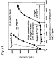
- the HC detection output of the sensor lowers as shown in Fig. 11, even though the exhaust includes a relatively high concentration of hydrocarbon (HC: 500 to 2000 ppmC), thereby causing another problem.
- An object of the present invention is to provide a hydrocarbon sensor using a mixed ion conductive electrolyte which is capable of accurately measuring the hydrocarbon concentration even in an atmosphere containing high levels of oxygen, by preventing the change and reduction in HC detection current output at the time when such a high concentration of oxygen is mixed with the hydrocarbon atmosphere.
- Another object of the present invention is to provide a hydrocarbon sensor comprising a cathode having a low electrode resistance.
- the hydrocarbon sensor of the present invention comprises a solid electrolyte formed of mixed ion conductor, an anode formed on one of surfaces of the electrolyte and a cathode formed on the other surface of the electrolyte, both opposed to each other, wherein the cathode is formed of an alloyed layer containing Al and a transition metal to be active to the hydrogen to proton.
- the transition metal is one or more elements selected from Groups 3 to 12 in the Periodic Table (IUPAC Inorganic Chemicals Nomenclatures (1989)).
- the transition metal may be preferably selected from active metals of Pt, Au, Ag, Cu, Pd, Mn, Fe, Ni, Co, and the like.
- Au may be used as the transition metal, to provide an Al-Au alloy for an alloyed layer of the cathode.
- a sintered layer or a sintered film, may be used as a alloyed layer, which may be formed of solid phase or liquid phase containing Al and the transition metal.
- the alloyed layer of the cathode may include one or more of Al-transition metal intermediate phases, and, preferably, a metal Al phase together with the intermediate phases.
- Au may be used since the intermediate phases of Au and Al have activity to dissociate protons to hydrogen and property to prevent oxygen to oxide ions and also considerable high electric conductivity required for the cathode.
- the hydrocarbon sensor of the present invention does not detect current owing to the conduction of the oxygen through the electrolyte.
- the presence of the Al component in the cathode alloyed layer shields oxygen from the atmosphere into the electrolyte by preventing the oxygen from being ionized at the cathode.
- the Au element in the alloyed layer prevents oxidation of the cathode, and effectively prevents an increase in cathode resistance due to the oxidation of the electrode.
- the similar effects are provided by cu, Ag Ni, Co, Pt, Pd and other noble metals, in the transition metals.
- the Au component does not hinder the hydrogenation of protons, thereby preventing reduction of the proton detection current.
- the Au component in the cathode accelerates the association reaction of protons from the solid electrolyte at the cathode, thereby accelerating the discharge of hydrogen at the cathode.
- the hydrocarbon sensor of the present invention can have high hydrocarbon detection performance even when a high concentration of oxygen becomes promptly included in the atmosphere, for example, in automobile exhausts, under measurement.
- the alloyed layer comprises a first layer containing an Al-Au intermediate phase which makes contact with the substrate and a second layer including a metal Al phase which covers the first layer.
- Another method of producing the hydrocarbon sensor may be used in which paste mainly containing Au and Al is applied to an electrolytic substrate to form a film, and fired to form an alloyed layer including Au and Al.
- the paste may be prepared of a mixture of powders of metals Au and Al.
- the alloyed layer is used as the cathode. This method may provide an alloyed layer including one or more of Al-Au intermediate phases, or an alloyed layer including Al-Au intermediate phases dispersed in a metal Al phase.
- the hydrocarbon sensor in accordance with the present invention comprises a solid electrolyte formed of a proton conductor.
- oxides having high conductivity to protons also have high conductivity to oxide ions.
- the solid electrolyte of the present invention is formed of a mixed-ion conductor, i.e., proton type-oxide-ion type conducting electrolyte.
- Such an electrolyte may preferably be formed of a Ba-Ce-based oxide which is high in sensitivity of hydrocarbon and which has high conductivity to oxide ions together with protons.
- the solid electrolyte is formed as a thin substrate, and electrodes are formed on both sides of the substrate, one electrode on each side.
- the cathode is formed of an alloyed layer containing Al and a transition metal to be active to the hydrogen to proton (excluding Al).
- the transition metal is one or more elements selected from Groups 3 to 12 in the Periodic Table(IUPAC Inorganic Chemicals Nomenclatures (1989)).
- the transition metal may be preferably selected from the metals of Pt, Au, Ag, Cu, Pd, Mn, Fe, Ni, Co, and the like. These metals exhibit the properties to discharge protons to hydrogen and at the same time, to activate oxygen to ions.
- Au may be used as the transition metal, to provide an Al-Au alloy layer having advantageous effect on the non-sensitivity to the presence of oxygen, as will described below, for an alloyed layer of the cathode. Therefore, in the preferred embodiment invention, the cathode formed of an Au-Al alloyed layer will be explained.
- Au is alloyed with Al to form Al-Au intermediate phases, as described below.
- These intermediate phases are hardly reactive with oxygen in an atmosphere at temperatures up to 900°C, whereby the cathode is not involved in the ionization of the oxygen from the atmosphere.
- the intermediate phases have considerably high electric conductivity.
- Al in the cathode alloyed layer may be present as a metal Al phase or an Al-Au intermediate phase, and that Au in the cathode alloyed layer is present as any of Al-Au intermediate phases.
- Au is exposed to the cathode surface as a metal Au phase (including an solid solution of Au wherein Al is dissolved). This is because the metal Au activates oxygen to ions on the surface of the cathode, thereby moving the oxide ions to the electrolyte. As a result, oxygen ion current as well as proton current is detected across the electrodes, thereby causing output errors.
- the alloyed layer for the cathode may preferably contains 4 to 90 wt% Al and 10 to 96 wt% Au based on the total weight of Au and Al in the alloyed layer. If the Al content is more than 90 wt%, because of less amount of Al 2 Au, the cathode will have higher electric resistance and lose the sensitivity of Hydrocarbon under high oxygen conditions in the atmosphere. On the other hand, if the Al content is lower than the 4 wt%, a free Au phase, i.e., a Au solid solution, appears with any Al-Au intermediate in the alloyed layer and readily may react to the oxygen in the atmosphere, adversely affecting the output current from the sensor due to the presence of the oxygen.
- a free Au phase i.e., a Au solid solution
- Such an alloyed layer may of the above composition may include both a metal Al phase and an Al-Au intermediate phase, as a first type of alloyed layer.
- the alloyed layer including both the metal Al phase and an Al 2 Au phase can be taken as an example.
- Al and Au may be present in the form of one, two or more Al-Au intermediate phases.
- the Al-Au intermediate phases may include Al 2 Au, AlAu, AlAu 2 , Al 2 Au 5 , AlAu 3 and AlAu 4 . Even if any of Al-Au intermediate phase is used solely without metal Al phase included, the Al-Au intermediate phase can effectively shield oxygen by preventing the ionization of oxygen, keep the cathode conductive and hydrogenate protons from the solid electrolyte to emit to the atmosphere.
- the alloyed layer of the above-mentioned cathode 2 may preferably comprise a first layer 21 including an Al-Au intermediate phase in contact with a solid electrolyte 1, and a second layer 22 including a metal Al phase covering the first layer 21.
- the metal Al phase of the second layer 22 makes contact with an atmosphere and can block oxygen in the atmosphere from the electrolyte.
- the Al-Au intermediate phase of the first layer 21 makes contact with the surface of the solid electrolyte, whereby the cathode 2 offers conductivity so as to function as an electrode and hydrogenates protons.
- This alloyed layer of the cathode can be formed as a sintered layer formed of the liquid or solid phases containing separately metals Au and Al.
- the sintered layer may be formed by applying a first layer mainly containing Au on the solid electrolyte and a second layer mainly containing Al on the first layer, and then sintering both layers to be alloyed, whereby an Al-Au intermediate phase is formed in the sintered layer.
- a method of producing the hydrocarbon sensor of the present invention will be described below.
- paste mainly containing Au is applied to an electrolytic substrate to form a film, and the film is fired to form an Au film.
- a paste mainly containing Al is applied to the Au film and fired to form an alloyed layer which is used as the cathode.
- the cathode comprises a first layer including an Al-Au intermediate phase in contact with the surface of the solid electrolyte and a second layer including a metal Al phase covering the first layer.
- Another form of the alloyed layer including both the metal Al and the Al-Au intermediate phase is a form of particles of the Al-Au intermediate phase which are dispersed in the metal Al phase.
- Another form of the alloyed layer may be one or more Al-Au intermediate phases but not containing any metal Al phase.
- Such an alloyed layer of the cathode can be formed as a sintered layer formed of the liquid or solid phases based on Au and Al.
- the alloy may preferably be produced by sintering a mixture of powders of metals Au and Al to make a sintered layer in which both Al phase and the Al-Au intermediate phase can also be included.
- Such a sintered alloyed layer for the cathode can be provided by applying a paste mainly containing Au and Al to the electrolytic substrate to form a Au-Al containing film, baking the substrate to remove the binder mixed in the film and then firing the film at suitable temperatures to make the sintered layer.
- pastes are used containing a mixture of particles or flakes of one of more metals, such as, for example, Au and/or Al, and an organic binder such as thermosetting resins.
- the pastes with proper viscosity are applied on the substrate surface of the solid electrolyte to form a thin pasted film and often dried to cure the resin to obtain the dried, hard film.
- the pasted film are heated to about 80 to 120°C to promote the curing reaction of the binder.
- the cured film which contains metal powders of flakes and resin, is fired at sintering temperatures sufficiently to sinter the metal components, for example, in the case of Au-Al alloyed layer from the Al and Au mixed powder in the paste, about 800 to 900°C or up to 1000°C for 0.5 to 5 hours or more.
- Al melts to react to the Au on the substrate to make a melt and/or Al-Au intermediate compounds such as Al 2 Au, and, during cooling, the Al-Au intermediate compound and, in the case of an unduly amount of Al, the residue of an Al phase.
- the Al-Au alloyed layer is formed on the substrate and used for a cathode of the sensor.
- a bake-out step may be provided for oxidizing and/or volatilizing the resin component to deposit the residual metal components on the substrate surface.
- the pasted film is held at 300 to 500°C.
- a Ba-Ce-based oxide represented by a conventional formula of BaCeO 3- ⁇ , may be used since it has high proton conductivity.
- it may be used as a sintered body represented by BaCe 1-x Ln x O 3- ⁇ wherein part of Ce may be replaced with another rare earth element Ln.
- Gadolinium Gd is preferably used as a rare earth element.
- a solid substrate 1 is a thin sintered body formed of a Ba-Ce-based oxide.
- a cathode 2 is formed of the above-mentioned alloyed layer 20 on one side of the substrate 1 while an anode 3 is formed on the other side of the substrate 1 oppositely to the cathodes respectively, thereby forming two sensors.
- the Hydrocarbon sensors of the present invention may use the conventional anodes such as a film of one or more of active metals of Pt, Au, Ag, Cu, Pd, Mn, Fe, Ni, Co, or the like, having a decomposition catalysis function for hydrocarbon.
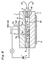
- a series connection comprising a DC power supply and a detection ammeter is connected between the cathode and the anode as shown in Fig. 1B.
- the hydrocarbon sensor of this invention can preferably be utilized for current-detection-type hydrocarbon sensor.
- a hydrocarbon diffusion-determining portion is provided on the side of the anode 3 of the solid electrolytic substrate 1 provided with the cathode 2 and the anode 3 on the sides thereof, one electrode on each side.
- the diffusion determining portion is constituted by attaching a ceramic substrate 7 to the electrolytic substrate 1 via an inorganic adhesive layer 8 so as to provide a hermetically sealed space around the anode 3, thereby to form an anode compartment 50.
- the inorganic adhesive layer 8 is provided with a diffusion determining hole 80 which passes through the adhesive layer 8 to provide gas passage between the atmosphere and the anode compartment 50, thereby allowing hydrocarbon to diffuse therebetween through the hole 80.
- This limiting-current-type sensor is a sensor of utilizing proton conductive limiting current for linearly detecting the concentration of hydrocarbon.
- the hydrocarbon in an atmosphere in which the sensor is placed diffuses through the diffusion determining hole 80, to enter the anode compartment 50 and reach the anode 3.
- the hydrocarbon having reached the anode 3 is dissociated to protons by electrolysis on the surface of the anode under a suitable voltage applied between the anode and cathode as shown in Fig. 6.
- the protons are conducted through the solid electrolytic substrate 1 under the applied voltage and discharged as hydrogen at the cathode.
- a current flows depending on a moving amount of the protons through the substrate, and a limiting current generates depending on the amount (concentration) of the hydrocarbon determined by the diffusion.
- a lead to be connected to the cathode to take out cathode current may be stuck to a part of the cathode by the above alloyed layer including Au and Al similarly to the cathode.
- the present embodiment is an example of hydrocarbon sensors comprising a solid electrolytic substrate of a Ba-Ce-based oxide, and a cathode of an alloyed layer comprising a first layer mainly containing Au in contact with one surface of the solid electrolytic substrate and a second layer mainly containing Al and covering the first layer.
- a thin sintered substrate having a composition of BaCe 0.8 Gd 0.2 O 3- ⁇ and measuring 10 mm x 10 mm in size and 0.45 mm in thickness.
- An Al-Au alloyed layer is used for the cathode 2 (active electrode), and the anode 3, the opposite electrode (reference electrode) to the cathode, is a platinum electrode.
- Au paste (N2764 Paste” made by Tanaka Kikinzoku Kogyo K. K.) and Al paste ("9203C Paste” made by Noritake Co., Ltd.) were applied to the electrolytic substrate by using screen printing technique.
- the Au paste was screened to the surface of the solid electrolyte 1 to produce an Au pasted film 21, and fired at 850°C to make an electrode layer.
- the Al paste was screened on the Au film such that the Al pasted film may cover the Au film and fired at 850°C for 1 hour to sinter into an Al-Au based alloyed layer 20.
- the sensors produced above as a prototype were examined as to whether to function as a hydrocarbon sensor in reality by using an actual automobile engine.
- the sensors were provided in an automobile exhaust pipe immediately on a downstream side from a cleaning catalytic apparatus.
- the sensor was heated and maintained at a temperature of 640 ⁇ 30°C, and then a voltage of 1.2 V was applied between the cathode and the anode (cathode is negative voltage).
- the exhausting gas is passed through the pipe with various concentrations of hydrocarbon changed, while the output current of the sensor was measured.
- the senor was provided inside a pipe with no catalytic devise in which high concentrations of oxygen would be present. As described above, the concentration of hydrocarbon was changed variously, and the output of the sensor was examined.
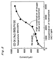
- Fig. 2 is a graph showing the relationship between the concentration of hydrocarbon and the output current of the sensor in the case where a catalytic devise is provided and oxygen was eliminated thereby.
- Fig. 2 also shows the case where no catalytic devise was provided and a high concentration of oxygen is mixed with hydrocarbon in the exhausting atmosphere.
- the output of the sensor of the present embodiment can increase depending on the hydrocarbon concentrations in the exhausting gas without including oxygen, and is substantially identical to that in the case of a high concentration of oxygen entering with the hydrocarbon into the exhausting gas.
- the conventional sensor in which a cathode is formed of platinum as well as the anode, as shown in Fig. 11, the output current from the sensor is lowered as a high concentration of oxygen was mixed with hydrocarbon.
- the senor of the present invention can accurately detect hydrocarbon even when a high concentration of oxygen was present together with hydrocarbon, and that the sensor has a high detection capability even when a high concentration of oxygen was mixed with hydrocarbon.
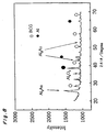
- Fig. 3 is a chart showing the X-ray diffraction of the alloyed layer of the cathode. It is found through the diffraction chart that while a part of Al has been oxidized to alumina, another part of Al is present in the form of a metal Al phase, and that an Al 2 Au intermediate phase is produced by the reaction of Au and Al. It is therefore believed that Al in the Al pasted film reacts with Au in the Au pasted film while the films are being fired, whereby the cathode 2 on the substrate 1 is formed of an alloyed layer which comprises the first layer 21 containing the Al-Au intermediate phase on the surface of the solid electrolyte, and the second layer 22 including the metal Al phase and covering the first layer as shown in Fig. 1A.
- the first layer includes an Al-Au intermediate phase under the second layer of aluminum.
- a alloyed layer having mixed phases including Au and Al is provided for the cathode as follows.
- a paste was prepared in which Al and Au are mixed to screen print as a single pasted film.
- the Au paste was mixed with the Al paste in a volume equal ratio.
- This mixed paste was screened onto the electrolyte as described above to form a film of 8 ⁇ m in thickness and fired at 850°C for 1 hour to form a single alloyed layer, and at the same time a Pt electrode also was fired as the anode, i.e., a reference electrode, to produce a hydrocarbon sensor.
- the composition of the alloyed layer of the cathode was examined by X-ray diffraction. As the result of the examination, an Al phase and an Al 2 Au phase were observed, as shown in Fig. 4.
- Fig. 5 shows the relationship between the hydrocarbon (HC) concentration in the atmosphere and the output current of the sensor.
- the output current of the sensor depending on the hydrocarbon concentration in the atmosphere where no oxygen was present was nearly identical with that in the case when a high concentration of oxygen was mixed with hydrocarbon in the atmosphere.
- the present embodiment shows an example of a limiting-current-type hydrocarbon sensor.
- a solid electrolyte 4 is formed of a sintered substrate having a composition of BaCe 0.8 Gd 0.2 O 3- ⁇ and measuring 10 mm x 10 mm in size and 0.45 mm in thickness.
- An anode 3 made of platinum is disposed on the surface of the sintered substrate 1.
- a cathode 2 is formed of a sintered body obtained by overlaying Al layer on an Au-Al layer with contact to the substrate.
- a hydrocarbon diffusion-determining portion is provided on the anode side, comprising an inorganic adhesive layer 8 is formed on the surface of the solid electrolyte around the anode 3 and a ceramic substrate 7 covering the and.
- a heater 9 is attached to the ceramic substrate 7 to heat the sensor to a desired temperature at the time of measurement.
- Au paste (TR1206 Paste” made by Tanaka Kikinzoku Kogyo K. K.) and Al paste (“9203C Paste” made by Noritake Co., Ltd.) were applied to the electrolytic substrate by screen printing just as in the case of Embodiment 1.
- Au paste was applied and fired at 850°C for 1 hours to form an Au layer as a first layer.
- Al paste was applied to the Au layer and fired at 850°C for 1 hour.
- this sensor produced as a prototype was examined as to whether to function as a hydrocarbon sensor by using an actual automobile engine.
- the sensor was heated at a temperature of 640 ⁇ 30°C using the heater 9, and a voltage of 1.2 V was applied across the cathode and anode (cathode is applied with negative voltage).
- the sensor was equipped in the exhausting duct of the engine where the hydrocarbon concentration in automobile exhaust was changed variously, and the sensor was examined immediately on the downstream side from a cleaning catalytic device in the duct through which the exhaust had passed. In addition, assuming that the catalyst was deteriorated completely, the sensor was also examined under a condition of no catalyst where the concentration of oxygen was high.
- Fig. 7 is a graph showing the relationship between the concentration of hydrocarbon and the output current of the sensor, in the case of the exhausting gas containing no oxygen with a catalyst and in the case of the exhausting gas containing high oxygen level of 0.4 to 2.7% in the exhausting atmosphere without catalyst.
- the sensor of the present embodiment gradually increases in output current depending on the concentration of hydrocarbon and substantially causes no difference between the absence of the oxygen and the high oxygen content. In comparison with the output current of the conventional sensor as shown in Fig. 11, having lowered when a high concentration of oxygen is mixed with hydrocarbon, it is found that the sensor of the present invention can accurately detect the concentration of hydrocarbon with less dependency on the oxygen content of the atmosphere.
- the characteristic of the hydrocarbon sensor was examined in the case of no oxygen in the exhausting gas when engine exhaust passed through a catalytic device, and in the case of high level of oxygen when engine exhaust did not pass.
- the output current of the sensor depending on the concentration of hydrocarbon was constant regardless of no oxygen present or a high level of oxygen mixed with hydrocarbon.
- the alloyed layer of the cathode including the Al 2 Au phase can effectively prevents oxygen penetration to the electrolyte, promotes hydrogen association and reduces the resistance of the electrode.
- the concentration of hydrocarbon can be detected accurately even when a high concentration of oxygen is present.
- This embodiment is an example of a hydrocarbon sensor comprising a solid electrolyte formed of a Ba-Ce-based oxide, a cathode of Al-Au alloyed layer, and an adhesive to connect a lead to the cathode to lead the cathode current to outer connections being also formed of the alloyed layer including Au and Al.
- an adhesive for the lead was attached on the cathode using two materials, the first material for the adhesive conventionally being of Pt and Au.
- the other adhesive for the lead was formed of an Al-Au alloyed layer, as used for the present embodiment.
- leads made of Au were connected to the attached adhesive layer in the cathode and the anode on the other side.
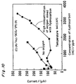
- the output current of the sensor drifted with respect to the hydrocarbon content in the exhausting atmosphere owing to the presence of oxygen, and the sensor is responded by oxygen as shown in Fig. 10.
- the lead adhesive also may act as a cathode at the portion where the adhesive makes contact with the cathode.
- the Au and Pt in the adhesive easily dissociates oxygen molecules from the atmosphere to cause a current to flow due to oxide ions detected.
Landscapes
- Chemical & Material Sciences (AREA)
- Health & Medical Sciences (AREA)
- Life Sciences & Earth Sciences (AREA)
- Analytical Chemistry (AREA)
- General Health & Medical Sciences (AREA)
- Pathology (AREA)
- Immunology (AREA)
- Physics & Mathematics (AREA)
- Engineering & Computer Science (AREA)
- Biochemistry (AREA)
- General Physics & Mathematics (AREA)
- Combustion & Propulsion (AREA)
- Medicinal Chemistry (AREA)
- Food Science & Technology (AREA)
- Molecular Biology (AREA)
- Chemical Kinetics & Catalysis (AREA)
- Electrochemistry (AREA)
- Measuring Oxygen Concentration In Cells (AREA)
Applications Claiming Priority (2)
| Application Number | Priority Date | Filing Date | Title |
|---|---|---|---|
| JP9493499 | 1999-04-01 | ||
| JP09493499A JP4241993B2 (ja) | 1999-04-01 | 1999-04-01 | 炭化水素センサ |
Publications (3)
| Publication Number | Publication Date |
|---|---|
| EP1041380A2 true EP1041380A2 (fr) | 2000-10-04 |
| EP1041380A3 EP1041380A3 (fr) | 2004-11-24 |
| EP1041380B1 EP1041380B1 (fr) | 2010-12-29 |
Family
ID=14123799
Family Applications (1)
| Application Number | Title | Priority Date | Filing Date |
|---|---|---|---|
| EP00106922A Expired - Lifetime EP1041380B1 (fr) | 1999-04-01 | 2000-03-31 | Capteur d'hydrocarbone et méthode pour sa production |
Country Status (4)
| Country | Link |
|---|---|
| US (2) | US6419808B1 (fr) |
| EP (1) | EP1041380B1 (fr) |
| JP (1) | JP4241993B2 (fr) |
| DE (1) | DE60045430D1 (fr) |
Cited By (2)
| Publication number | Priority date | Publication date | Assignee | Title |
|---|---|---|---|---|
| EP1199561A1 (fr) * | 2000-10-16 | 2002-04-24 | Matsushita Electric Industrial Co., Ltd. | Capteur d'hydrocarbone et méthode pour sa production |
| US7235171B2 (en) * | 2001-07-24 | 2007-06-26 | Matsushita Electric Industrial Co., Ltd. | Hydrogen sensor, hydrogen sensor device and method of detecting hydrogen concentration |
Families Citing this family (8)
| Publication number | Priority date | Publication date | Assignee | Title |
|---|---|---|---|---|
| JP4730635B2 (ja) * | 2001-03-21 | 2011-07-20 | 独立行政法人産業技術総合研究所 | 炭化水素ガスセンサ及び炭化水素ガス濃度測定方法 |
| EP1283420A1 (fr) * | 2001-08-08 | 2003-02-12 | Loggion AG | Méthode et appareil pour mesurer une concentration des hydrocarbures en solution aqueuse |
| US20030162305A1 (en) * | 2002-02-25 | 2003-08-28 | Daniel Alvarez | Gas contaminant detection and quantification method |
| JP3993122B2 (ja) | 2002-05-29 | 2007-10-17 | 株式会社デンソー | ガスセンサ素子及び含水素ガスの測定方法 |
| US6936160B2 (en) * | 2002-10-28 | 2005-08-30 | Pti Technologies, Inc. | Wireless MEMS sensing device |
| US7011600B2 (en) * | 2003-02-28 | 2006-03-14 | Fallbrook Technologies Inc. | Continuously variable transmission |
| US8158562B2 (en) | 2007-04-27 | 2012-04-17 | Clearwater International, Llc | Delayed hydrocarbon gel crosslinkers and methods for making and using same |
| JP5707180B2 (ja) * | 2011-03-07 | 2015-04-22 | 株式会社日本自動車部品総合研究所 | ガスセンサ素子およびガス濃度検出方法 |
Family Cites Families (13)
| Publication number | Priority date | Publication date | Assignee | Title |
|---|---|---|---|---|
| DE2206216C3 (de) * | 1972-02-10 | 1978-12-21 | Robert Bosch Gmbh, 7000 Stuttgart | Meßfühler für die Bestimmung des Sauerstoffgehaltes in Abgasen, vorwiegend von Verbrennungsmotoren, sowie Verfahren zur Herstellung solcher Meßfühler |
| US4021326A (en) * | 1972-06-02 | 1977-05-03 | Robert Bosch G.M.B.H. | Electro-chemical sensor |
| US4279666A (en) * | 1979-11-28 | 1981-07-21 | General Motors Corporation | Oxidized aluminum overcoat for solid electrolyte sensor |
| WO1993012190A1 (fr) * | 1991-12-19 | 1993-06-24 | Cookson Group Plc | Compositions adhesives conductrices a base de polymeres depolymerisables thermiquement |
| US5472580A (en) * | 1994-06-09 | 1995-12-05 | General Motors Corporation | Catalytic converter diagnostic sensor |
| WO1997012413A2 (fr) * | 1995-09-25 | 1997-04-03 | Roth-Technik Gmbh & Co. Forschung Für Automobil- Und Umwelttechnik | Materiau d'electrode pour capteurs d'hydrocarbures |
| JP3311218B2 (ja) * | 1995-11-02 | 2002-08-05 | 松下電器産業株式会社 | 炭化水素センサ |
| JPH1048175A (ja) * | 1996-08-07 | 1998-02-20 | Akebono Brake Res & Dev Center Ltd | ガスセンサ−用電極材料とそれを使用した固体電解質型co2 ガスセンサー |
| EP1029828B1 (fr) * | 1996-10-28 | 2003-02-26 | Kabushiki Kaisha Ohara | Vitro-céramiques conducteurs d'ions de lithium, cellules électriques et senseurs de gaz utilisant ces vitro-céramiques |
| DE19712315C2 (de) * | 1997-03-24 | 1999-02-04 | Heraeus Electro Nite Int | Brenngassensitives Elektrodenmaterial für elektrochemische Sensoren |
| JP3841513B2 (ja) | 1997-04-23 | 2006-11-01 | 松下電器産業株式会社 | 炭化水素センサ |
| KR100319947B1 (ko) * | 1998-04-06 | 2002-01-09 | 마츠시타 덴끼 산교 가부시키가이샤 | 탄화수소 센서 |
| JP3795227B2 (ja) | 1998-05-25 | 2006-07-12 | 松下電器産業株式会社 | 炭化水素センサ |
-
1999
- 1999-04-01 JP JP09493499A patent/JP4241993B2/ja not_active Expired - Lifetime
-
2000
- 2000-03-30 US US09/539,317 patent/US6419808B1/en not_active Expired - Lifetime
- 2000-03-31 EP EP00106922A patent/EP1041380B1/fr not_active Expired - Lifetime
- 2000-03-31 DE DE60045430T patent/DE60045430D1/de not_active Expired - Lifetime
-
2001
- 2001-03-13 US US09/804,229 patent/US6342267B2/en not_active Expired - Lifetime
Cited By (3)
| Publication number | Priority date | Publication date | Assignee | Title |
|---|---|---|---|---|
| EP1199561A1 (fr) * | 2000-10-16 | 2002-04-24 | Matsushita Electric Industrial Co., Ltd. | Capteur d'hydrocarbone et méthode pour sa production |
| US6638406B2 (en) | 2000-10-16 | 2003-10-28 | Matsushita Electric Industrial Co., Ltd. | Hydrocarbon sensor and method for producing the same |
| US7235171B2 (en) * | 2001-07-24 | 2007-06-26 | Matsushita Electric Industrial Co., Ltd. | Hydrogen sensor, hydrogen sensor device and method of detecting hydrogen concentration |
Also Published As
| Publication number | Publication date |
|---|---|
| US6342267B2 (en) | 2002-01-29 |
| JP4241993B2 (ja) | 2009-03-18 |
| US20010010290A1 (en) | 2001-08-02 |
| JP2000292409A (ja) | 2000-10-20 |
| DE60045430D1 (de) | 2011-02-10 |
| EP1041380A3 (fr) | 2004-11-24 |
| US6419808B1 (en) | 2002-07-16 |
| EP1041380B1 (fr) | 2010-12-29 |
Similar Documents
| Publication | Publication Date | Title |
|---|---|---|
| US9304102B2 (en) | Amperometric electrochemical sensors, sensor systems and detection methods | |
| EP0949505B1 (fr) | Capteur de hydrocarbons | |
| US20020017461A1 (en) | NOx sensor | |
| KR20170067775A (ko) | 전류 측정 고체 전해질 센서 및 NH3 및 NOx 검출 센서 | |
| JP3587290B2 (ja) | NOxガスセンサ | |
| EP1041380B1 (fr) | Capteur d'hydrocarbone et méthode pour sa production | |
| CN1226965A (zh) | 氧气固态传感器 | |
| US20100122916A1 (en) | Sensor with electrodes of a same material | |
| US20050061670A1 (en) | NOx sensing cell, manufacturing method for the NOx sensing cell, and NOx sensing device including the NOx sensing cell | |
| US6346178B1 (en) | Simplified wide range air fuel ratio sensor | |
| EP0766085B1 (fr) | Dispositif électrochimique | |
| EP0271917B1 (fr) | Capteur de rapport air/combustible | |
| Shoemaker et al. | Cyclic voltammetry applied to an oxygen-ion-conducting solid electrolyte as an active electrocatalytic gas sensor | |
| JP2002243692A (ja) | 窒素酸化物ガスセンサ | |
| US6797138B1 (en) | Gas senior design and method for forming the same | |
| JP2000292409A5 (fr) | ||
| JP4153238B2 (ja) | 電気化学的酸素ポンプセルおよびそれを用いた窒素酸化物検知装置 | |
| JP3795227B2 (ja) | 炭化水素センサ | |
| JP2002005883A (ja) | 窒素酸化物ガスセンサ | |
| JPH11337518A5 (fr) | ||
| JP4213939B2 (ja) | ガス検出装置 | |
| JPH11132995A (ja) | 窒素酸化物検出装置 | |
| JPH11295267A (ja) | 炭化水素センサ |
Legal Events
| Date | Code | Title | Description |
|---|---|---|---|
| PUAI | Public reference made under article 153(3) epc to a published international application that has entered the european phase |
Free format text: ORIGINAL CODE: 0009012 |
|
| AK | Designated contracting states |
Kind code of ref document: A2 Designated state(s): AT BE CH CY DE DK ES FI FR GB GR IE IT LI LU MC NL PT SE |
|
| AX | Request for extension of the european patent |
Free format text: AL;LT;LV;MK;RO;SI |
|
| PUAL | Search report despatched |
Free format text: ORIGINAL CODE: 0009013 |
|
| AK | Designated contracting states |
Kind code of ref document: A3 Designated state(s): AT BE CH CY DE DK ES FI FR GB GR IE IT LI LU MC NL PT SE |
|
| AX | Request for extension of the european patent |
Extension state: AL LT LV MK RO SI |
|
| 17P | Request for examination filed |
Effective date: 20050524 |
|
| AKX | Designation fees paid |
Designated state(s): DE FR GB |
|
| 17Q | First examination report despatched |
Effective date: 20060808 |
|
| 17Q | First examination report despatched |
Effective date: 20060808 |
|
| RAP1 | Party data changed (applicant data changed or rights of an application transferred) |
Owner name: PANASONIC CORPORATION |
|
| GRAP | Despatch of communication of intention to grant a patent |
Free format text: ORIGINAL CODE: EPIDOSNIGR1 |
|
| GRAS | Grant fee paid |
Free format text: ORIGINAL CODE: EPIDOSNIGR3 |
|
| GRAA | (expected) grant |
Free format text: ORIGINAL CODE: 0009210 |
|
| AK | Designated contracting states |
Kind code of ref document: B1 Designated state(s): DE FR GB |
|
| REG | Reference to a national code |
Ref country code: GB Ref legal event code: FG4D |
|
| REF | Corresponds to: |
Ref document number: 60045430 Country of ref document: DE Date of ref document: 20110210 Kind code of ref document: P |
|
| REG | Reference to a national code |
Ref country code: DE Ref legal event code: R096 Ref document number: 60045430 Country of ref document: DE Effective date: 20110210 |
|
| PLBE | No opposition filed within time limit |
Free format text: ORIGINAL CODE: 0009261 |
|
| STAA | Information on the status of an ep patent application or granted ep patent |
Free format text: STATUS: NO OPPOSITION FILED WITHIN TIME LIMIT |
|
| GBPC | Gb: european patent ceased through non-payment of renewal fee |
Effective date: 20110331 |
|
| 26N | No opposition filed |
Effective date: 20110930 |
|
| REG | Reference to a national code |
Ref country code: FR Ref legal event code: ST Effective date: 20111130 |
|
| REG | Reference to a national code |
Ref country code: DE Ref legal event code: R097 Ref document number: 60045430 Country of ref document: DE Effective date: 20110930 |
|
| PG25 | Lapsed in a contracting state [announced via postgrant information from national office to epo] |
Ref country code: FR Free format text: LAPSE BECAUSE OF NON-PAYMENT OF DUE FEES Effective date: 20110331 |
|
| PG25 | Lapsed in a contracting state [announced via postgrant information from national office to epo] |
Ref country code: GB Free format text: LAPSE BECAUSE OF NON-PAYMENT OF DUE FEES Effective date: 20110331 |
|
| PGFP | Annual fee paid to national office [announced via postgrant information from national office to epo] |
Ref country code: DE Payment date: 20190319 Year of fee payment: 20 |
|
| REG | Reference to a national code |
Ref country code: DE Ref legal event code: R071 Ref document number: 60045430 Country of ref document: DE |