EP1042782B1 - Installation de traitement sous vide - Google Patents
Installation de traitement sous vide Download PDFInfo
- Publication number
- EP1042782B1 EP1042782B1 EP98958771A EP98958771A EP1042782B1 EP 1042782 B1 EP1042782 B1 EP 1042782B1 EP 98958771 A EP98958771 A EP 98958771A EP 98958771 A EP98958771 A EP 98958771A EP 1042782 B1 EP1042782 B1 EP 1042782B1
- Authority
- EP
- European Patent Office
- Prior art keywords
- potential
- plant
- unit
- sensor
- plant according
- Prior art date
- Legal status (The legal status is an assumption and is not a legal conclusion. Google has not performed a legal analysis and makes no representation as to the accuracy of the status listed.)
- Expired - Lifetime
Links
Images



Classifications
-
- H—ELECTRICITY
- H01—ELECTRIC ELEMENTS
- H01J—ELECTRIC DISCHARGE TUBES OR DISCHARGE LAMPS
- H01J37/00—Discharge tubes with provision for introducing objects or material to be exposed to the discharge, e.g. for the purpose of examination or processing thereof
- H01J37/32—Gas-filled discharge tubes
- H01J37/32917—Plasma diagnostics
- H01J37/32935—Monitoring and controlling tubes by information coming from the object and/or discharge
-
- H—ELECTRICITY
- H01—ELECTRIC ELEMENTS
- H01J—ELECTRIC DISCHARGE TUBES OR DISCHARGE LAMPS
- H01J37/00—Discharge tubes with provision for introducing objects or material to be exposed to the discharge, e.g. for the purpose of examination or processing thereof
- H01J37/32—Gas-filled discharge tubes
- H01J37/32917—Plasma diagnostics
- H01J37/3299—Feedback systems
Definitions
- the present invention relates to a vacuum treatment plant having at least one vacuum treatment chamber, wherein a first part of the system is connected to an electrical system reference potential - usually ground potential - in the vacuum chamber, a further part is provided, which is at a plant reference potential of at least ⁇ 12 V deviating electrical potential is set and wherein at this further part at least one sensor and / or at least one actuator is arranged, further with an electronic unit which is operatively connected on the input side and / or output side with the sensor and / or actuator.
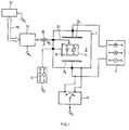
- FIG. 1 Such a previously known vacuum treatment plant, as an example with a plasma discharge path, is shown schematically and will be discussed with reference to this figure.
- a plasma discharge gap is provided in this example between electrodes 3 a and 3 b .
- the discharge path designated 3 is electrically operated by a supply unit 5, be it DC, pulsed DC, AC or AC and superimposed DC, wherein the AC signal frequency can be in the Hz to high frequency or even in the microwave range ,
- Fig. 1 the electrical leads to the discharge path 3 of the chamber 1 shown electrically isolated.
- the system reference potential usually ground potential, ⁇ o , arguemen.
- This is shown schematically with the options selector switch 7. It is customary, for example, the housing 1 and one of the electrodes 3 a , 3 b to ground.
- the vacuum chamber 1 shows a further part 9, for example a substrate carrier, an instrument carrier, a further electrode, etc., wherein this part 9, which is drawn separately for reasons of explanation, can also be one of the electrodes 3 a , 3 b .
- This part 9 is now not at potential ⁇ 0 .
- This is illustrated with the unit 4, corresponding to an impedance and / or source replacement image.
- the present invention is based on problems associated with part 9 in the chamber 1, which is not placed on the system reference potential ⁇ o . It is based on otherwise arbitrary electrical potential ⁇ 9 , ie deviating from ⁇ o , ie at DC potential, at AC potential, at superimposed AC and DC potential, at a pulsed DC potential , wherein frequency-wise the AC potential can be located in the high frequency range or even in the microwave range. If, for example, the part 9 is a substrate carrier, it may, with electrically insulated mounting, be operated with respect to ⁇ 0 to self-bias potential of the discharge. If the part 9 one of the electrodes 3 a , 3 b in Hf plasma generation, it is with respect to ⁇ o at high Hf potential.
- the reason for the reference potential laying is that, for example, in Hf operation of the discharge path, simple protective measures are possible, as shown schematically at 15, for example by means of also placed on ⁇ o shields.
- the signal communication between unit 13 and one of these higher-level unit 17, such as a higher-level computer is particularly simple.
- the communication interface 19 has, as a reference potential, the system reference potential ⁇ o which, as mentioned, is usually ground potential. Subsumed under the communication link between unit 11 and unit 13, which in Fig.
- 1 is schematized with 21, and possibly feed signals for the unit 11 from an external power supply, so the voltages supplied to the unit 11, by suitable electronic means, to the measuring or control range of usually a few volts reduced, including, for example, voltage divider , like in the US 5 270 637 described, and / or suitable rectifier and filter elements, like in the US 5,144,231 shown to be used.
- the transmitter comprises coupling elements in the form of, for example, separation amplifiers or photo-insulators. Again, the transmitter outside the plasma chamber (1) is arranged.
- a vacuum treatment plant as defined in claim 1.
- an electronic unit connected to a sensor and / or actuator is installed inside the vacuum treatment chamber.
- a vacuum treatment plant in which such processes often occur, is in particular a plant in which a discharge path is used.
- the mentioned further part 9 preferably forms one of the discharge electrodes, or is a part exposed to the discharge, which is operated at a floating potential and thus, for example, assumes self-bias potential of the discharge or which is operated at a certain potential.
- the mentioned at least one sensor is a temperature sensor
- the actuator is a heating and / or cooling device, preferably a multi-zone heating or cooling, more preferably in this case the further part 9 is formed by a workpiece carrier.
- a temperature control can be realized or, and in a preferred manner, a temperature control.
- the sensor or a plurality of provided sensors takes on the controlled variable temperature or temperature distribution.
- the control variable measurement signal is amplified and supplied on the output side to a higher, interference-insensitive level of a higher-level unit, what target / actual value comparison is made and what possibly also the controller with desired Characteristic is realized.
- the returned signal is supplied by the superordinated unit of the mentioned electronics unit at the part 9, which outputs the temperature or temperature distribution actuator signal to the or the temperature actuator (s). Otherwise, and preferably, the electronics unit directly forms the desired / actual value comparison and the desired regulator characteristic.
- temperature accuracies of at least ⁇ 5 ° C at control ranges of some 100 ° C full-scale easily accessible, preferably at least ⁇ 2 ° C or even at least ⁇ 1 ° C.
- Such a temperature control is particularly highly desirable if the mentioned part 9 is a workpiece carrier in the system or if the part 9 is a target arrangement of the system.
- the mentioned part 9 forms a workpiece holder.
- the sensor verifies the presence or absence of a workpiece on the receptacle. Includes the workpiece holder, which forms the mentioned part 9, electrostatically or by negative pressure on Workpiece-holding members, so further preferably the aforementioned or another sensor is provided for checking the workpiece holder, and it is preferably acted back from the sensor via the electronics unit to the mentioned holder.
- the mentioned further part 9 is provided directly in the region of a gas inlet into the vacuum chamber and the sensor is designed as a gas flow sensor.
- the electronics unit acts on the output side on a control valve arrangement in a gas duct for gas inlet.
- the mentioned part 9 is provided directly in the region of a workpiece.
- the further part 9 is provided on a target arrangement, where the sensor measures or detects the temperature of the target and / or its state.
- the mentioned electronic unit operated at the potential of the part 9, according to the invention provided within the vacuum chamber; at least their input stage for the sensor or output stage for the actuator are arranged directly in the region of the mentioned sensors or actuators and therefore in the vacuum chamber.
- the further part 9 is placed at AC and / or DC potential with respect to the system reference potential, or is arranged electrically isolated from the system reference potential.
- AC includes in particular the Hf range, but may extend into the microwave range.
- the further part is a substrate or workpiece carrier.
- sensors and / or actuators such as for the temperature position or control, as mentioned, often desirable.
- the potential difference ⁇ 0 - ⁇ 9 is preferably as follows: 12 V ⁇
- Peak-to-peak voltage V pp at the mentioned part 9 and with respect to plant reference potential at AC, in particular Hf-operation, are preferably in the range 25 V ⁇ V PP ⁇ 2 ⁇ ' ⁇ 000 ⁇ V . preferably: 50 V ⁇ V pp ⁇ 500 V ,
- the mentioned electronic unit comprises at least one digital, preferably programmable unit, preferably at least one programmable digital logic module and / or at least one digital computer unit, preferably at least one microprocessor and / or microcomputer.
- memory means for operating programs are provided on the electronic unit, if necessary.
- the electronic unit is, more preferably, arranged directly mechanically on the mentioned further part 9.
- the mentioned electronic unit is preferably enclosed by a Faraday cage, which is preferably placed on the potential of the part 9.
- connections from and / or to the electronics unit are at least partially guided via galvanic separation points and / or via RF filter arrangements.
- Such filter arrangements are preferably enclosed by a Faraday cage arrangement lying on the system reference potential.
- the mentioned electronic unit communicates with a higher-level setting and / or monitoring unit, for example a host computer, which is arranged outside the vacuum chamber.
- Signal connections between The electronics unit and the higher-level unit preferably take place via a galvanic separation point, such as via transformer transformers, preferably via optical fibers.
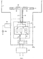
- Fig. 2 are already based on Fig. 1 explained parts the same as in Fig. 1 designated.
- Part 9, which is based on Fig. 1 has been explained, is basically a part that is not placed on investment potential ⁇ 0 , so quite well can act on one of the electrodes 3 a , 3 b , is, as schematized with the unit 4, via an impedance and / or a Signal source arrangement (substitute network selection) based on system reference potential ⁇ 0 .
- Fig. 1 is, primary, as a reference potential of the electronic unit 13, as shown with the galvanic connection 25, the potential ⁇ 9 the part 9 switched.
- the electronics unit 13 is installed inside the chamber 1; Preferably, but not necessarily, the unit 13 is arranged mechanically or structurally on the part 9. This results in optimally short connections 21 between unit 13 and sensors or actuators 11, and in particular the signals transmitted thereto are not disturbed by the potential difference or by the voltage U 4 ( ⁇ 9 minus ⁇ 0 ). This realizes a significant increase in the measuring or positioning accuracy because it is no longer necessary to process small actuating or measuring signals, superimposed on large "common mode" signals, at the unit 13. Thus, a signal conditioning can be done without interference on the unit 13, and low-power signals can be amplified to such high levels that a downstream continuation, in particular lead out corresponding signals from the chamber 1 is much less problematic.
- Fig. 3 a section of a preferred inventive system.
- the part 9 as one of the in the Fig. 1 or 2 shown discharge electrode 3 a , 3 b used for a Hf plasma discharge.
- this part 9 forms according to Fig. 3 Substrate carrier for in the chamber 1 to be treated substrates 32.
- Part 9 is now called Substrate Carrier 9.
- a Temperature sensor 34 installed, as a temperature control element a Schuwiderstandsan extract 36.
- Measuring signal line 38 from the sensor assembly 34 and control signal lines 40 to the controller 36 are guided to the electronic unit 13, which includes a microprocessor with memory unit for operating programs.
- an actuator control output stage 42 for example with a corresponding digital / analog converter
- a power supply unit 44 for the entire unit 13
- a MeßvertownrverEntr input stage 46 with a corresponding analog / digital converter.
- the unit 13 is, as shown with the galvanic connection 25, operated at the electrical potential of the substrate carrier 9. Furthermore, the unit 13 is preferably surrounded by a Faraday cage 38 operated at the potential of the substrate carrier 9, as represented by the galvanic connection 26. Output signals from the unit 13, which are guided out of the chamber 1, which is at plant reference potential ⁇ 0 , ie ground potential, as well as input signals, which are supplied from outside the chamber 1 of the unit 13 are at least partially via a galvanic separation unit 50, as mentioned above transformer transformers and / or optical fibers or optocouplers, led. Preferably, an RF filter arrangement 52 is additionally provided between the galvanic separation unit 50 and the electronics unit 13.
- the filter arrangement 52 is preferably arranged in a Faraday cage 54, the latter being operated at installation reference potential ⁇ 0 .
- a Faraday cage 54 Corresponding to the operating frequency range, bushings through the Faraday cages 48 and 54 are limited in their diameter.
- the substrate carrier 9 As one of the RF plasma discharge electrodes, eg at Operated 13.56 MHz, the substrate carrier 9 is connected via a matchbox 56 to the RF generator 58 for the RF plasma discharge.
- Feedthroughs, such as for electrical energy, a cooling or heating medium, etc., through the Faraday cage 48 have for the frequency range mentioned diameter of at most 5 cm, preferably less than 1 cm.
- the voltage supply of the unit 13 is preferably carried out via a galvanic isolation to the unit 50 and via corresponding filter of the filter assembly 52nd
- a workpiece carrier table 60 for example a lifting table
- a plurality of sensors 62 or of heating and / or cooling elements 64 are arranged in a matrix-like manner.
- the output signals of the sensors 62 are fed to the electronics unit 63.
- the electronic unit 63 is, as shown with the galvanic connection 66, placed on the potential of acting as part 9 workpiece receiving table 60.
- the output signals of the sensors 62 are amplified in the sense of a drastic increase in the subsequent signal-to-noise ratio and transmitted on the output side to a unit 63 downstream, preferably arranged outside the vacuum chamber electronics unit 65.
- the Output signals of the higher-level electronics unit 65 back to the inventively potential-based electronic unit 63 out, which they signal and / or impedance moderately forwarded to the heating and / or cooling elements 64 passed.
- the input signals from the sensors 62 are compared, for example, in their entirety with a DESIRED temperature distribution along the workpiece carrier table 60, as schematically indicated at S, to the unit 65, and at the unit 65 of the target / actual value comparison made and, with a corresponding characteristic, the transmission elements Z 1 and Z 2 formed.
- the electronic unit 63 forms directly target / actual value difference and the control elements according to Z 1 and Z 2 .
- the desired temperature distribution T soll is supplied directly to the electronic unit 63, which is provided according to the invention, or stored thereon.
- the temperature or temperature distribution or, in general, the state on other parts of the system can be detected and possibly regulated, in particular on a target arrangement.
- a gas sensor 70 is arranged in the region of a workpiece 74 deposited on a workpiece carrier table 72.
- the evaluating electronic unit 73 is, as shown schematically with the galvanic connection 76, together with the sensor 70 on the Potential of the table 72, acting here as part 9, placed.
- the workpiece carrier table 72 can also be set to a desired bias potential, depending on the treatment process carried out, be it a DC and / or an AC potential, as shown in FIG Fig. 6 is shown schematically with the source 80 and the dashed connections, with respect to the applied as a reference potential ⁇ 0 to the wall 78 of the vacuum chamber ground potential.
- the electronic unit 73 sets a valve arrangement 84, which regulates the gas flow G from a gas tank 88 and from a gas injection 86.
- the procedure according to the invention is particularly preferably used in vacuum treatment plants in which plasma discharges are realized, in particular in reactive or non-reactive sputter coating or sputter etching treatment plants or in plasma-assisted CVD treatment plants, but possibly also in arc evaporation plants or electron beam evaporation plants, in general in plants in which Precise measurements or precise control interventions are required there, where high voltages can prevail or occur during operation and in relation to the system reference potential.
Landscapes
- Physics & Mathematics (AREA)
- Engineering & Computer Science (AREA)
- Plasma & Fusion (AREA)
- Chemical & Material Sciences (AREA)
- Analytical Chemistry (AREA)
- Chemical Vapour Deposition (AREA)
- Plasma Technology (AREA)
- Vaporization, Distillation, Condensation, Sublimation, And Cold Traps (AREA)
- Processing Of Solid Wastes (AREA)
- Superconductors And Manufacturing Methods Therefor (AREA)
- Physical Vapour Deposition (AREA)
- Physical Or Chemical Processes And Apparatus (AREA)
Claims (16)
- Installation de traitement sous vide avec au moins une chambre de traitement sous vide (1), une partie de l'installation étant reliée à un potentiel électrique de référence d'installation (φ0), une autre partie (9) étant prévue dans la chambre de traitement sous vide (1), laquelle autre partie est adaptée pour être mise à un potentiel (φ9) différent d'au moins 12 V du potentiel de référence d'installation (φ0), et au moins un capteur et/ou au moins un élément de réglage (11 ; 36, 34 ; 62, 64 ; 70) étant disposés sur cette autre partie (9), en outre avec une unité électronique (13 ; 63 ; 73) qui est reliée côté entrée et/ou côté sortie au capteur et/ou à l'élément de réglage, l'unité électronique (13 ; 63 ; 73) étant adaptée pour fonctionner à un autre potentiel de référence qui est le potentiel (φ9) de l'autre partie (9), et l'unité électronique (13 ; 63 ; 73) étant montée à l'intérieur de la chambre de traitement sous vide.
- Installation de traitement sous vide selon la revendication 1, dans laquelle il est prévu une voie de décharge dans la chambre de traitement sous vide (1), l'autre partie, de préférence,• étant l'une des électrodes de décharge ou• une autre partie qui est soumise à la décharge et qui est adaptée pour fonctionner à un potentiel flottant ou à un potentiel déterminé.
- Installation selon la revendication 1 ou 2, caractérisée par le fait qu'au moins un capteur et au moins un élément de réglage sont prévus et que le capteur est un capteur de température et l'élément de réglage est un dispositif de chauffage et/ou de refroidissement, de préférence pour un chauffage ou un refroidissement à zones multiples.
- Installation selon l'une des revendications 1 à 3, caractérisée par le fait que l'autre partie est un logement de pièce et le capteur ou un autre capteur est prévu pour la vérification de la présence d'une pièce, de préférence sur la partie des organes de retenue agissant de manière électrostatique ou par vide partiel étant alors prévus et le capteur ou l'autre capteur étant alors prévu pour la vérification de la fixation de pièce et ayant une rétroaction sur la fixation de préférence par l'intermédiaire de l'unité électronique.
- Installation selon l'une des revendications 1 à 4, caractérisée par le fait que l'autre partie est prévue directement dans la zone d'une admission de gaz ou d'une pièce, que le capteur ou un autre capteur est un capteur de flux gazeux, et que l'unité électronique est en liaison fonctionnelle, côté sortie, avec un dispositif de réglage dans une arrivée de gaz à l'admission de gaz.
- Installation selon l'une des revendications 1 à 3, ou 5 dans le cas où elle est considérée comme dépendante des revendications 1 à 3, caractérisée par le fait que l'autre partie est un dispositif cible et que le capteur ou un autre capteur détecte la température de la cible et/ou son état.
- Installation selon l'une des revendications 1 à 6, caractérisée par le fait que l'unité électronique comprend une unité numérique, de préférence programmable, de préférence au moins un composant logique numérique programmable et/ou une unité de calcul numérique, de préférence un microprocesseur et/ou un micro-ordinateur, avec des moyens de mémorisation pour les programmes d'exploitation.
- Installation selon l'une des revendications 1 à 7, caractérisée par le fait qu'elle comprend des moyens pour mettre l'autre partie (9), par rapport au potentiel de référence d'installation (φ0), à un potentiel AC et/ou à un potentiel DC, AC pouvant comprendre la plage HF et micro-ondes, ou que l'autre partie (9) est disposée électriquement isolée.
- Installation selon l'une des revendications 1 à 5 ; ou 7, 8 dans le cas où elles sont considérées comme dépendantes des revendications 1 à 5, caractérisée par le fait que l'autre partie (9) est un support de substrat.
- Installation selon l'une des revendications 1 à 9, avec des moyens pour mettre l'autre partie (9), par rapport au potentiel de référence d'installation (φ0), à un potentiel HF (φ9) dans une plage de fréquences :entre 100 kHz et 100 MHz,
de préférenceentre 5 MHz et 50 MHz,et encore de préférence avec des moyens pour mettre l'autre partie (9), par rapport au potentiel de référence d'installation (φ0), à une différence de potentiel ou tension ayant une valeur de pointe Vpp pour laquelle on a :
de préférence à 13,56 MHz environ,
de préférence
- Installation selon l'une des revendications 1 à 9, avec des moyens pour mettre le potentiel (φ9) de l'autre partie de telle sorte qu'il est différent du potentiel de référence φ0 de l'installation de

de préférence
- Installation selon l'une des revendications 1 à 11, caractérisée par le fait que l'unité électronique (13, 13') est disposée mécaniquement sur l'autre partie (9).
- Installation selon l'une des revendications 1 à 12, caractérisée par le fait que l'unité électronique (13, 13') est entourée par une cage de Faraday (48) se trouvant de préférence au potentiel de référence (φ0) de l'installation.
- Installation selon l'une des revendications 1 à 13, avec des moyens pour mettre l'autre partie à un potentiel HF, les lignes conduisant de l'extérieur de la chambre à l'unité électronique (13, 13') dans la chambre de traitement sous vide (1) et/ou les lignes conduisant de cette dernière à l'extérieur passant au moins en partie par un dispositif de filtrage HF (52) qui est entouré de préférence par une cage de Faraday (54) se trouvant au potentiel de référence (φ0) de l'installation.
- Installation selon l'une des revendications 1 à 14, caractérisée par le fait que l'unité électronique (13, 13') est reliée à une unité de réglage et/ou de surveillance de rang supérieur, de préférence à un ordinateur principal, et que cette liaison s'effectue au moins en partie par une unité d'isolation électrique (30, 50).
- Installation selon la revendication 14, ou 15 dans le cas où elle est considérée comme dépendante de la revendication 14, caractérisée par le fait qu'au moins une partie des lignes passe par des points de coupure électrique.
Applications Claiming Priority (3)
| Application Number | Priority Date | Filing Date | Title |
|---|---|---|---|
| CH295897 | 1997-12-23 | ||
| CH295897 | 1997-12-23 | ||
| PCT/CH1998/000548 WO1999034398A1 (fr) | 1997-12-23 | 1998-12-22 | Installation de traitement sous vide |
Publications (2)
| Publication Number | Publication Date |
|---|---|
| EP1042782A1 EP1042782A1 (fr) | 2000-10-11 |
| EP1042782B1 true EP1042782B1 (fr) | 2008-10-15 |
Family
ID=4245469
Family Applications (1)
| Application Number | Title | Priority Date | Filing Date |
|---|---|---|---|
| EP98958771A Expired - Lifetime EP1042782B1 (fr) | 1997-12-23 | 1998-12-22 | Installation de traitement sous vide |
Country Status (6)
| Country | Link |
|---|---|
| US (2) | US6527927B1 (fr) |
| EP (1) | EP1042782B1 (fr) |
| JP (1) | JP2002500087A (fr) |
| AT (1) | ATE411610T1 (fr) |
| DE (2) | DE19882026D2 (fr) |
| WO (1) | WO1999034398A1 (fr) |
Families Citing this family (5)
| Publication number | Priority date | Publication date | Assignee | Title |
|---|---|---|---|---|
| AU3547400A (en) * | 1999-03-30 | 2000-11-02 | Chessen Group Inc. | Temperature controller for plasma processing |
| US6741446B2 (en) * | 2001-03-30 | 2004-05-25 | Lam Research Corporation | Vacuum plasma processor and method of operating same |
| WO2011015538A1 (fr) * | 2009-08-03 | 2011-02-10 | Leibniz-Institut Für Plasmaforschung Und Technologie E. V. | Dispositif de production d'un plasma non thermique à pression atmosphérique |
| JP6591657B2 (ja) * | 2017-02-24 | 2019-10-16 | アプライド マテリアルズ インコーポレイテッドApplied Materials,Incorporated | 真空システムで使用するためのキャリア、真空処理のためのシステム、及び基板の真空処理のための方法 |
| BE1026859B1 (nl) * | 2018-10-22 | 2020-07-14 | Soleras Advanced Coatings Bv | Magnetron met geïntegreerd circuit voor het monitoren en controle |
Citations (2)
| Publication number | Priority date | Publication date | Assignee | Title |
|---|---|---|---|---|
| US5365147A (en) * | 1990-11-28 | 1994-11-15 | Nichimen Kabushiki Kaisha | Plasma stabilizing apparatus employing feedback controls |
| WO1998011412A1 (fr) * | 1996-09-11 | 1998-03-19 | Berrian Donald W | Procedes et appareil de mesure de temperatures a un potentiel eleve |
Family Cites Families (7)
| Publication number | Priority date | Publication date | Assignee | Title |
|---|---|---|---|---|
| US4407708A (en) * | 1981-08-06 | 1983-10-04 | Eaton Corporation | Method for operating a magnetron sputtering apparatus |
| US4409087A (en) * | 1982-05-18 | 1983-10-11 | The Perkin-Elmer Corp. | Wafer detection circuitry for high vacuum use |
| JPS5916970A (ja) * | 1982-07-15 | 1984-01-28 | Citizen Watch Co Ltd | イオンプレ−テイングにおける蒸発材の蒸発量検知及び制御方法 |
| US4913790A (en) * | 1988-03-25 | 1990-04-03 | Tokyo Electron Limited | Treating method |
| JP2892787B2 (ja) * | 1990-07-20 | 1999-05-17 | 東京エレクトロン株式会社 | 電気信号の抽出方法 |
| ATE144004T1 (de) * | 1991-04-12 | 1996-10-15 | Balzers Hochvakuum | Verfahren und anlage zur beschichtung mindestens eines gegenstandes |
| DE4203672C2 (de) * | 1991-10-01 | 1993-09-30 | Messer Griesheim Gmbh | Verfahren zur Minimierung von plasmabedingten Störeffekten auf kapazitive Abtastsysteme |
-
1998
- 1998-12-22 DE DE19882026T patent/DE19882026D2/de not_active Expired - Fee Related
- 1998-12-22 DE DE59814306T patent/DE59814306D1/de not_active Expired - Lifetime
- 1998-12-22 EP EP98958771A patent/EP1042782B1/fr not_active Expired - Lifetime
- 1998-12-22 WO PCT/CH1998/000548 patent/WO1999034398A1/fr not_active Ceased
- 1998-12-22 JP JP2000526944A patent/JP2002500087A/ja not_active Withdrawn
- 1998-12-22 AT AT98958771T patent/ATE411610T1/de not_active IP Right Cessation
-
2000
- 2000-06-05 US US09/587,452 patent/US6527927B1/en not_active Expired - Lifetime
-
2002
- 2002-12-31 US US10/334,564 patent/US7105080B2/en not_active Expired - Lifetime
Patent Citations (2)
| Publication number | Priority date | Publication date | Assignee | Title |
|---|---|---|---|---|
| US5365147A (en) * | 1990-11-28 | 1994-11-15 | Nichimen Kabushiki Kaisha | Plasma stabilizing apparatus employing feedback controls |
| WO1998011412A1 (fr) * | 1996-09-11 | 1998-03-19 | Berrian Donald W | Procedes et appareil de mesure de temperatures a un potentiel eleve |
Non-Patent Citations (2)
| Title |
|---|
| KONUMA M.: "Film Deposition by Plasma Techniques", 1992, SPRINGER VERLAG * |
| LAIMER J.: "Plasmaunterstützte Abscheidung aus der Gasphase zur Erzeugung dünner harter Titannitrid-Schichten.", 20 January 1989, DISSERTATION TECHNISCHE UNIVERSITCT WIEN 1987 * |
Also Published As
| Publication number | Publication date |
|---|---|
| DE59814306D1 (de) | 2008-11-27 |
| EP1042782A1 (fr) | 2000-10-11 |
| JP2002500087A (ja) | 2002-01-08 |
| WO1999034398A1 (fr) | 1999-07-08 |
| US20030098231A1 (en) | 2003-05-29 |
| ATE411610T1 (de) | 2008-10-15 |
| US6527927B1 (en) | 2003-03-04 |
| US7105080B2 (en) | 2006-09-12 |
| DE19882026D2 (de) | 2000-11-30 |
Similar Documents
| Publication | Publication Date | Title |
|---|---|---|
| DE69605643T2 (de) | Verfahren und vorrichtung zur messung eines zonenflusses in einem plasma | |
| DE69918063T2 (de) | Reaktor zur radiofrequenz betriebenen plasma-aktivierten chemischen dampfabscheidung und verfahren | |
| DE69836857T2 (de) | Gerät und verfahren zur steuerung der ionenenergie und plasmadichte in einer plasma-behandlungsvorrichtung | |
| DE69719316T2 (de) | Elektrostatischer scheibenhalter mit dynamischer ruckkoppelung | |
| DE69734706T2 (de) | Vorrichtungen zur phasendifferenzsteuerung in einem plasmabehandlungssystem | |
| DE69814687T2 (de) | Plasmavorrichtung mit einem mit einer spannungsquelle verbundenen metallteil, das zwischen einer rf-plasma-anregungsquelle und dem plasma angeordnet ist | |
| DE69630589T2 (de) | Verfahren und vorrichtung zur plasmaerzeugung | |
| DE4029984C2 (fr) | ||
| DE69727624T2 (de) | Induktiv gekoppelter HDP-CVD-Reaktor | |
| EP1884984B1 (fr) | Système d'analyse d'ions basé sur un analyseur de distribution d'énergie d'ions utilisant un champ électrique retardé | |
| CN101720499B (zh) | 用于局部化功率传送的分布式功率装置 | |
| DE4441206A1 (de) | Einrichtung für die Unterdrückung von Überschlägen in Kathoden-Zerstäubungseinrichtungen | |
| DE202010014805U1 (de) | Heissrandring mit geneigter oberer Oberfläche | |
| WO1997027613A1 (fr) | Source ionique pour systeme a faisceau ionique | |
| EP2173618B1 (fr) | Détecteur de distance capacitif robuste | |
| KR20180062348A (ko) | 범용 비침습성 챔버 임피던스 측정 시스템 및 연관된 방법들 | |
| CN101943594A (zh) | 自补偿的电容液位检测器 | |
| WO2000019483A1 (fr) | Chambre de traitement sous vide et procede de traitement de surface | |
| EP1042782B1 (fr) | Installation de traitement sous vide | |
| DE60130744T2 (de) | Induktiv gekoppeltes Plasma-Ätzgerät mit aktiver Steuerung der RF-Spitzenspannung | |
| EP0796505B1 (fr) | Reacteur au plasma et procede permettant de le faire fonctionner | |
| WO2024023244A1 (fr) | Dispositif de commande et procédé d'actionnement de circuit d'adaptation d'impédance pour un système de production de plasma et système de production de plasma de ce type | |
| US10586688B2 (en) | Inductive current sensor on printed circuit board | |
| EP2417619B1 (fr) | Chambre de traitement à alimentation en plasma modulée | |
| DE10260614B4 (de) | Plasmaparametersteuerung unter Verwendung von Lerndaten |
Legal Events
| Date | Code | Title | Description |
|---|---|---|---|
| PUAI | Public reference made under article 153(3) epc to a published international application that has entered the european phase |
Free format text: ORIGINAL CODE: 0009012 |
|
| 17P | Request for examination filed |
Effective date: 20000418 |
|
| AK | Designated contracting states |
Kind code of ref document: A1 Designated state(s): AT BE CH DE ES FI FR GB IE IT LI NL PT SE |
|
| RAP1 | Party data changed (applicant data changed or rights of an application transferred) |
Owner name: UNAXIS BALZERS AKTIENGESELLSCHAFT |
|
| 17Q | First examination report despatched |
Effective date: 20040604 |
|
| GRAP | Despatch of communication of intention to grant a patent |
Free format text: ORIGINAL CODE: EPIDOSNIGR1 |
|
| RAP1 | Party data changed (applicant data changed or rights of an application transferred) |
Owner name: OC OERLIKON BALZERS AG |
|
| GRAS | Grant fee paid |
Free format text: ORIGINAL CODE: EPIDOSNIGR3 |
|
| GRAA | (expected) grant |
Free format text: ORIGINAL CODE: 0009210 |
|
| AK | Designated contracting states |
Kind code of ref document: B1 Designated state(s): AT BE CH DE ES FI FR GB IE IT LI NL PT SE |
|
| REG | Reference to a national code |
Ref country code: GB Ref legal event code: FG4D Free format text: NOT ENGLISH Ref country code: CH Ref legal event code: EP |
|
| REG | Reference to a national code |
Ref country code: IE Ref legal event code: FG4D Free format text: LANGUAGE OF EP DOCUMENT: GERMAN |
|
| REF | Corresponds to: |
Ref document number: 59814306 Country of ref document: DE Date of ref document: 20081127 Kind code of ref document: P |
|
| NLV1 | Nl: lapsed or annulled due to failure to fulfill the requirements of art. 29p and 29m of the patents act | ||
| PG25 | Lapsed in a contracting state [announced via postgrant information from national office to epo] |
Ref country code: ES Free format text: LAPSE BECAUSE OF FAILURE TO SUBMIT A TRANSLATION OF THE DESCRIPTION OR TO PAY THE FEE WITHIN THE PRESCRIBED TIME-LIMIT Effective date: 20090126 |
|
| PG25 | Lapsed in a contracting state [announced via postgrant information from national office to epo] |
Ref country code: PT Free format text: LAPSE BECAUSE OF FAILURE TO SUBMIT A TRANSLATION OF THE DESCRIPTION OR TO PAY THE FEE WITHIN THE PRESCRIBED TIME-LIMIT Effective date: 20090316 Ref country code: NL Free format text: LAPSE BECAUSE OF FAILURE TO SUBMIT A TRANSLATION OF THE DESCRIPTION OR TO PAY THE FEE WITHIN THE PRESCRIBED TIME-LIMIT Effective date: 20081015 Ref country code: FI Free format text: LAPSE BECAUSE OF FAILURE TO SUBMIT A TRANSLATION OF THE DESCRIPTION OR TO PAY THE FEE WITHIN THE PRESCRIBED TIME-LIMIT Effective date: 20081015 |
|
| BERE | Be: lapsed |
Owner name: OC OERLIKON BALZERS AG Effective date: 20081231 |
|
| REG | Reference to a national code |
Ref country code: IE Ref legal event code: FD4D |
|
| PG25 | Lapsed in a contracting state [announced via postgrant information from national office to epo] |
Ref country code: IE Free format text: LAPSE BECAUSE OF FAILURE TO SUBMIT A TRANSLATION OF THE DESCRIPTION OR TO PAY THE FEE WITHIN THE PRESCRIBED TIME-LIMIT Effective date: 20081015 |
|
| PLBE | No opposition filed within time limit |
Free format text: ORIGINAL CODE: 0009261 |
|
| STAA | Information on the status of an ep patent application or granted ep patent |
Free format text: STATUS: NO OPPOSITION FILED WITHIN TIME LIMIT |
|
| PG25 | Lapsed in a contracting state [announced via postgrant information from national office to epo] |
Ref country code: SE Free format text: LAPSE BECAUSE OF FAILURE TO SUBMIT A TRANSLATION OF THE DESCRIPTION OR TO PAY THE FEE WITHIN THE PRESCRIBED TIME-LIMIT Effective date: 20090115 Ref country code: IT Free format text: LAPSE BECAUSE OF FAILURE TO SUBMIT A TRANSLATION OF THE DESCRIPTION OR TO PAY THE FEE WITHIN THE PRESCRIBED TIME-LIMIT Effective date: 20081015 |
|
| 26N | No opposition filed |
Effective date: 20090716 |
|
| PG25 | Lapsed in a contracting state [announced via postgrant information from national office to epo] |
Ref country code: BE Free format text: LAPSE BECAUSE OF NON-PAYMENT OF DUE FEES Effective date: 20081231 |
|
| PG25 | Lapsed in a contracting state [announced via postgrant information from national office to epo] |
Ref country code: AT Free format text: LAPSE BECAUSE OF NON-PAYMENT OF DUE FEES Effective date: 20081222 |
|
| REG | Reference to a national code |
Ref country code: CH Ref legal event code: PFA Owner name: OERLIKON ADVANCED TECHNOLOGIES AG, LI Free format text: FORMER OWNER: OC OERLIKON BALZERS AG, LI |
|
| PGFP | Annual fee paid to national office [announced via postgrant information from national office to epo] |
Ref country code: CH Payment date: 20140320 Year of fee payment: 16 |
|
| REG | Reference to a national code |
Ref country code: FR Ref legal event code: TP Owner name: OERLIKON ADVANCED TECHNOLOGIES AG, LI Effective date: 20140627 |
|
| REG | Reference to a national code |
Ref country code: GB Ref legal event code: 732E Free format text: REGISTERED BETWEEN 20140710 AND 20140716 |
|
| REG | Reference to a national code |
Ref country code: DE Ref legal event code: R082 Ref document number: 59814306 Country of ref document: DE Representative=s name: BOCKHORNI & KOLLEGEN PATENT- UND RECHTSANWAELT, DE |
|
| REG | Reference to a national code |
Ref country code: DE Ref legal event code: R082 Ref document number: 59814306 Country of ref document: DE Representative=s name: BOCKHORNI & BRUENTJEN PARTNERSCHAFT PATENTANWA, DE Effective date: 20141216 Ref country code: DE Ref legal event code: R082 Ref document number: 59814306 Country of ref document: DE Representative=s name: BOCKHORNI & KOLLEGEN PATENT- UND RECHTSANWAELT, DE Effective date: 20141216 Ref country code: DE Ref legal event code: R081 Ref document number: 59814306 Country of ref document: DE Owner name: OERLIKON ADVANCED TECHNOLOGIES AG, LI Free format text: FORMER OWNER: OC OERLIKON BALZERS AG, BALZERS, LI Effective date: 20141216 |
|
| PGFP | Annual fee paid to national office [announced via postgrant information from national office to epo] |
Ref country code: FR Payment date: 20141208 Year of fee payment: 17 |
|
| REG | Reference to a national code |
Ref country code: CH Ref legal event code: PL |
|
| PG25 | Lapsed in a contracting state [announced via postgrant information from national office to epo] |
Ref country code: CH Free format text: LAPSE BECAUSE OF NON-PAYMENT OF DUE FEES Effective date: 20141231 Ref country code: LI Free format text: LAPSE BECAUSE OF NON-PAYMENT OF DUE FEES Effective date: 20141231 |
|
| REG | Reference to a national code |
Ref country code: FR Ref legal event code: ST Effective date: 20160831 |
|
| PG25 | Lapsed in a contracting state [announced via postgrant information from national office to epo] |
Ref country code: FR Free format text: LAPSE BECAUSE OF NON-PAYMENT OF DUE FEES Effective date: 20151231 |
|
| PGFP | Annual fee paid to national office [announced via postgrant information from national office to epo] |
Ref country code: DE Payment date: 20161213 Year of fee payment: 19 Ref country code: GB Payment date: 20161221 Year of fee payment: 19 |
|
| REG | Reference to a national code |
Ref country code: DE Ref legal event code: R119 Ref document number: 59814306 Country of ref document: DE |
|
| GBPC | Gb: european patent ceased through non-payment of renewal fee |
Effective date: 20171222 |
|
| PG25 | Lapsed in a contracting state [announced via postgrant information from national office to epo] |
Ref country code: DE Free format text: LAPSE BECAUSE OF NON-PAYMENT OF DUE FEES Effective date: 20180703 |
|
| PG25 | Lapsed in a contracting state [announced via postgrant information from national office to epo] |
Ref country code: GB Free format text: LAPSE BECAUSE OF NON-PAYMENT OF DUE FEES Effective date: 20171222 |