EP1043050A2 - Dispositif et procédé de raffinage d' un matériau contenant une substance polymérisant facilement - Google Patents
Dispositif et procédé de raffinage d' un matériau contenant une substance polymérisant facilement Download PDFInfo
- Publication number
- EP1043050A2 EP1043050A2 EP00302234A EP00302234A EP1043050A2 EP 1043050 A2 EP1043050 A2 EP 1043050A2 EP 00302234 A EP00302234 A EP 00302234A EP 00302234 A EP00302234 A EP 00302234A EP 1043050 A2 EP1043050 A2 EP 1043050A2
- Authority
- EP
- European Patent Office
- Prior art keywords
- distillation column
- heat exchanger
- vapor
- boiler
- condenser
- Prior art date
- Legal status (The legal status is an assumption and is not a legal conclusion. Google has not performed a legal analysis and makes no representation as to the accuracy of the status listed.)
- Granted
Links
- 238000000034 method Methods 0.000 title claims abstract description 31
- 239000000126 substance Substances 0.000 title claims abstract description 23
- 238000007670 refining Methods 0.000 title claims abstract description 16
- 238000004821 distillation Methods 0.000 claims abstract description 171
- 230000014759 maintenance of location Effects 0.000 claims abstract description 33
- CERQOIWHTDAKMF-UHFFFAOYSA-N Methacrylic acid Chemical group CC(=C)C(O)=O CERQOIWHTDAKMF-UHFFFAOYSA-N 0.000 claims description 37
- 239000012808 vapor phase Substances 0.000 claims description 21
- 238000010438 heat treatment Methods 0.000 claims description 19
- -1 acrylic ester Chemical class 0.000 claims description 13
- 239000000463 material Substances 0.000 claims description 4
- 239000007788 liquid Substances 0.000 description 26
- 238000006116 polymerization reaction Methods 0.000 description 19
- NIXOWILDQLNWCW-UHFFFAOYSA-N 2-Propenoic acid Natural products OC(=O)C=C NIXOWILDQLNWCW-UHFFFAOYSA-N 0.000 description 14
- SMZOUWXMTYCWNB-UHFFFAOYSA-N 2-(2-methoxy-5-methylphenyl)ethanamine Chemical compound COC1=CC=C(C)C=C1CCN SMZOUWXMTYCWNB-UHFFFAOYSA-N 0.000 description 13
- QTBSBXVTEAMEQO-UHFFFAOYSA-N Acetic acid Chemical compound CC(O)=O QTBSBXVTEAMEQO-UHFFFAOYSA-N 0.000 description 12
- 229920000642 polymer Polymers 0.000 description 9
- NIXOWILDQLNWCW-UHFFFAOYSA-M Acrylate Chemical compound [O-]C(=O)C=C NIXOWILDQLNWCW-UHFFFAOYSA-M 0.000 description 8
- 230000000694 effects Effects 0.000 description 8
- 239000012535 impurity Substances 0.000 description 8
- 238000010992 reflux Methods 0.000 description 8
- 230000003247 decreasing effect Effects 0.000 description 7
- 230000000379 polymerizing effect Effects 0.000 description 7
- HGINCPLSRVDWNT-UHFFFAOYSA-N Acrolein Chemical compound C=CC=O HGINCPLSRVDWNT-UHFFFAOYSA-N 0.000 description 6
- 239000002826 coolant Substances 0.000 description 6
- XLYOFNOQVPJJNP-UHFFFAOYSA-N water Substances O XLYOFNOQVPJJNP-UHFFFAOYSA-N 0.000 description 6
- 238000009835 boiling Methods 0.000 description 5
- 239000000203 mixture Substances 0.000 description 5
- 238000003466 welding Methods 0.000 description 5
- NNJPGOLRFBJNIW-HNNXBMFYSA-N (-)-demecolcine Chemical compound C1=C(OC)C(=O)C=C2[C@@H](NC)CCC3=CC(OC)=C(OC)C(OC)=C3C2=C1 NNJPGOLRFBJNIW-HNNXBMFYSA-N 0.000 description 4
- WSFSSNUMVMOOMR-UHFFFAOYSA-N Formaldehyde Chemical compound O=C WSFSSNUMVMOOMR-UHFFFAOYSA-N 0.000 description 4
- 239000003638 chemical reducing agent Substances 0.000 description 4
- XBDQKXXYIPTUBI-UHFFFAOYSA-N dimethylselenoniopropionate Natural products CCC(O)=O XBDQKXXYIPTUBI-UHFFFAOYSA-N 0.000 description 4
- 210000002310 elbow joint Anatomy 0.000 description 4
- 239000012530 fluid Substances 0.000 description 4
- 238000003556 assay Methods 0.000 description 3
- 239000006227 byproduct Substances 0.000 description 3
- 230000005465 channeling Effects 0.000 description 3
- 238000009833 condensation Methods 0.000 description 3
- 238000010276 construction Methods 0.000 description 3
- 239000000110 cooling liquid Substances 0.000 description 3
- 238000010586 diagram Methods 0.000 description 3
- 238000009826 distribution Methods 0.000 description 3
- 239000007789 gas Substances 0.000 description 3
- 238000004519 manufacturing process Methods 0.000 description 3
- 239000012071 phase Substances 0.000 description 3
- 230000002265 prevention Effects 0.000 description 3
- 229910001220 stainless steel Inorganic materials 0.000 description 3
- 239000010935 stainless steel Substances 0.000 description 3
- 229920002554 vinyl polymer Polymers 0.000 description 3
- JHPBZFOKBAGZBL-UHFFFAOYSA-N (3-hydroxy-2,2,4-trimethylpentyl) 2-methylprop-2-enoate Chemical compound CC(C)C(O)C(C)(C)COC(=O)C(C)=C JHPBZFOKBAGZBL-UHFFFAOYSA-N 0.000 description 2
- GOXQRTZXKQZDDN-UHFFFAOYSA-N 2-Ethylhexyl acrylate Chemical compound CCCCC(CC)COC(=O)C=C GOXQRTZXKQZDDN-UHFFFAOYSA-N 0.000 description 2
- QIGBRXMKCJKVMJ-UHFFFAOYSA-N Hydroquinone Chemical compound OC1=CC=C(O)C=C1 QIGBRXMKCJKVMJ-UHFFFAOYSA-N 0.000 description 2
- OFOBLEOULBTSOW-UHFFFAOYSA-N Propanedioic acid Natural products OC(=O)CC(O)=O OFOBLEOULBTSOW-UHFFFAOYSA-N 0.000 description 2
- 239000002253 acid Substances 0.000 description 2
- 230000015572 biosynthetic process Effects 0.000 description 2
- 230000003197 catalytic effect Effects 0.000 description 2
- 238000006243 chemical reaction Methods 0.000 description 2
- 230000005494 condensation Effects 0.000 description 2
- VZCYOOQTPOCHFL-UPHRSURJSA-N maleic acid Chemical compound OC(=O)\C=C/C(O)=O VZCYOOQTPOCHFL-UPHRSURJSA-N 0.000 description 2
- 239000011976 maleic acid Substances 0.000 description 2
- 125000002496 methyl group Chemical group [H]C([H])([H])* 0.000 description 2
- 230000003647 oxidation Effects 0.000 description 2
- 238000007254 oxidation reaction Methods 0.000 description 2
- 235000019260 propionic acid Nutrition 0.000 description 2
- IUVKMZGDUIUOCP-BTNSXGMBSA-N quinbolone Chemical compound O([C@H]1CC[C@H]2[C@H]3[C@@H]([C@]4(C=CC(=O)C=C4CC3)C)CC[C@@]21C)C1=CCCC1 IUVKMZGDUIUOCP-BTNSXGMBSA-N 0.000 description 2
- 239000000243 solution Substances 0.000 description 2
- VZCYOOQTPOCHFL-UHFFFAOYSA-N trans-butenedioic acid Natural products OC(=O)C=CC(O)=O VZCYOOQTPOCHFL-UHFFFAOYSA-N 0.000 description 2
- 125000000391 vinyl group Chemical group [H]C([*])=C([H])[H] 0.000 description 2
- WJFKNYWRSNBZNX-UHFFFAOYSA-N 10H-phenothiazine Chemical compound C1=CC=C2NC3=CC=CC=C3SC2=C1 WJFKNYWRSNBZNX-UHFFFAOYSA-N 0.000 description 1
- IJGRMHOSHXDMSA-UHFFFAOYSA-N Atomic nitrogen Chemical compound N#N IJGRMHOSHXDMSA-UHFFFAOYSA-N 0.000 description 1
- KYXHKHDZJSDWEF-LHLOQNFPSA-N CCCCCCC1=C(CCCCCC)C(\C=C\CCCCCCCC(O)=O)C(CCCCCCCC(O)=O)CC1 Chemical compound CCCCCCC1=C(CCCCCC)C(\C=C\CCCCCCCC(O)=O)C(CCCCCCCC(O)=O)CC1 KYXHKHDZJSDWEF-LHLOQNFPSA-N 0.000 description 1
- GAWIXWVDTYZWAW-UHFFFAOYSA-N C[CH]O Chemical group C[CH]O GAWIXWVDTYZWAW-UHFFFAOYSA-N 0.000 description 1
- STNJBCKSHOAVAJ-UHFFFAOYSA-N Methacrolein Chemical compound CC(=C)C=O STNJBCKSHOAVAJ-UHFFFAOYSA-N 0.000 description 1
- 125000000484 butyl group Chemical group [H]C([*])([H])C([H])([H])C([H])([H])C([H])([H])[H] 0.000 description 1
- 230000000052 comparative effect Effects 0.000 description 1
- 150000001875 compounds Chemical class 0.000 description 1
- 238000001816 cooling Methods 0.000 description 1
- 239000000498 cooling water Substances 0.000 description 1
- 239000000539 dimer Substances 0.000 description 1
- 229910001873 dinitrogen Inorganic materials 0.000 description 1
- 150000002148 esters Chemical class 0.000 description 1
- 125000001495 ethyl group Chemical group [H]C([H])([H])C([H])([H])* 0.000 description 1
- 125000003055 glycidyl group Chemical group C(C1CO1)* 0.000 description 1
- 201000006747 infectious mononucleosis Diseases 0.000 description 1
- 239000003112 inhibitor Substances 0.000 description 1
- 239000007791 liquid phase Substances 0.000 description 1
- 239000011259 mixed solution Substances 0.000 description 1
- 239000000178 monomer Substances 0.000 description 1
- 229950000688 phenothiazine Drugs 0.000 description 1
- 238000000746 purification Methods 0.000 description 1
- 239000007921 spray Substances 0.000 description 1
- 125000001424 substituent group Chemical group 0.000 description 1
- 238000003786 synthesis reaction Methods 0.000 description 1
- 238000009834 vaporization Methods 0.000 description 1
- 230000008016 vaporization Effects 0.000 description 1
- 238000009736 wetting Methods 0.000 description 1
Images


Classifications
-
- B—PERFORMING OPERATIONS; TRANSPORTING
- B01—PHYSICAL OR CHEMICAL PROCESSES OR APPARATUS IN GENERAL
- B01D—SEPARATION
- B01D3/00—Distillation or related exchange processes in which liquids are contacted with gaseous media, e.g. stripping
- B01D3/14—Fractional distillation or use of a fractionation or rectification column
-
- B—PERFORMING OPERATIONS; TRANSPORTING
- B01—PHYSICAL OR CHEMICAL PROCESSES OR APPARATUS IN GENERAL
- B01D—SEPARATION
- B01D3/00—Distillation or related exchange processes in which liquids are contacted with gaseous media, e.g. stripping
- B01D3/14—Fractional distillation or use of a fractionation or rectification column
- B01D3/32—Other features of fractionating columns ; Constructional details of fractionating columns not provided for in groups B01D3/16 - B01D3/30
- B01D3/322—Reboiler specifications
-
- B—PERFORMING OPERATIONS; TRANSPORTING
- B01—PHYSICAL OR CHEMICAL PROCESSES OR APPARATUS IN GENERAL
- B01D—SEPARATION
- B01D5/00—Condensation of vapours; Recovering volatile solvents by condensation
- B01D5/0003—Condensation of vapours; Recovering volatile solvents by condensation by using heat-exchange surfaces for indirect contact between gases or vapours and the cooling medium
- B01D5/0012—Vertical tubes
-
- B—PERFORMING OPERATIONS; TRANSPORTING
- B01—PHYSICAL OR CHEMICAL PROCESSES OR APPARATUS IN GENERAL
- B01D—SEPARATION
- B01D5/00—Condensation of vapours; Recovering volatile solvents by condensation
- B01D5/0057—Condensation of vapours; Recovering volatile solvents by condensation in combination with other processes
- B01D5/006—Condensation of vapours; Recovering volatile solvents by condensation in combination with other processes with evaporation or distillation
- B01D5/0063—Reflux condensation
-
- Y—GENERAL TAGGING OF NEW TECHNOLOGICAL DEVELOPMENTS; GENERAL TAGGING OF CROSS-SECTIONAL TECHNOLOGIES SPANNING OVER SEVERAL SECTIONS OF THE IPC; TECHNICAL SUBJECTS COVERED BY FORMER USPC CROSS-REFERENCE ART COLLECTIONS [XRACs] AND DIGESTS
- Y10—TECHNICAL SUBJECTS COVERED BY FORMER USPC
- Y10S—TECHNICAL SUBJECTS COVERED BY FORMER USPC CROSS-REFERENCE ART COLLECTIONS [XRACs] AND DIGESTS
- Y10S159/00—Concentrating evaporators
- Y10S159/42—Seals
Definitions
- This invention relates to a method for refining an easily polymerizable matter-containing substance and an apparatus therefor. More particularly, it relates to a method for refining (meth)acrylic acid and/or a (meth)acrylic ester while preventing the acid and/or the ester from being polymerized particularly in the vapor phase and an apparatus to be used therefor.
- the condenser In a distillation column with a condenser and a re-boiler, the condenser is connected to the top of the distillation column via a (inter)connecting line and the re-boiler is positioned near the lower part of the distillation column via a (inter)connecting line.
- the feed material such as the impurities-containing (meth)acrylic acid is supplied to the distillation column and distilled therein.
- the vapor distilled from (meth)acrylic acid which has entered the condenser via the connecting line is condensed and apart thereof is returned to the distillation column and the rest thereof is recovered as distillate D or subjected further to a subsequent treatment.
- the liquid containing (meth)acrylic acid through the bottom of the distillation column is supplied to the re-boiler and reboiled therein, with the result that the vapor containing (meth)acrylic acid will be returned via the connecting line to the distillation column.
- U.S. Patent No. 3,988,213 discloses a method for preventing the vapor of a vinyl compound from condensing or polymerizing by providing a distillation column with a jacket.
- U.S. Patent No. 3,717,553 discloses a distillation column which, by having an opening formed near the wall of a tray tower and consequently allowed to have the wall of its own wetted, is enabled to prevent a vinyl monomer from polymerizing.
- An object of the invention is to provide a method for refining an easily polymerizable matter-containing substance such as (meth)acrylic acid and/or a (meth)acrylic ester, which attains the refinement efficiently by efficiently preventing the matter under treatment from polymerizing in a vapor phase part of a connecting line interposed between a distillation column and a heat exchanger, and an apparatus to be used therefor.
- an easily polymerizable matter-containing substance such as (meth)acrylic acid and/or a (meth)acrylic ester
- the present inventors have pursued a study and consequently found that in the distillation of (meth)acrylic acid and/or a (meth)acrylic ester, the compound being distilled is prevented from polymerizing by causing a vertical shell-and-tube heat exchanger to be supported by the distillation column and by branching a vapor line interconnecting them from the direct shell part of the distillation column or setting a condenser directly on the top of the distillation column or setting a re-boiler in the bottom of the distillation thereby decreasing the vapor phase volume thereof.
- This invention has been achieved as a result.
- the first aspect of this invention can provide a method for refining and separating an easily polymerizable matter-containing substance by using a distillation column furnished with a heat exchanger, which method is characterized by setting the linear velocity of the vapor in a connecting line interconnecting the distillation column and the heat exchanger at a level of not less than 5 m per second and the retention time of the vapor in the connecting line at a level of not more than 3 seconds.
- the second aspect of this invention can provide an apparatus for refining an easily polymerizable matter-containing substance by using a distillation column furnished with a heat exchanger, which apparatus is characterized by using a condenser as the heat exchanger and having the condenser directly set on the top of the distillation column.
- the third aspect of this invention can provide an apparatus for refining an easily polymerizable matter-containing substance by using a distillation column furnished with a heat exchanger, which apparatus is characterized by using a re-boiler as the heat exchanger and the re-boiler being disposed directly inside the distillation column in the lower part thereof wherein a vapor guide provided above the heating tubes for the re-boiler is opened into the vapor phase part of the column and a down-take is furnished outside the heating tubes.
- this invention in refining and separating an easily polymerizable matter-containing substance by using a distillation column furnished with a heat exchanger, is capable of effectively preventing the vapor of the easily polymerizable matter-containing substance from polymerizing by setting the linear velocity of the vapor in a (inter)connecting line interconnecting the distillation column and the heat exchanger at a level of not less than 5 m per second and the retention time of the vapor in the connecting line at a level of not more than 3 seconds.
- the apparatus of this invention for refining an easily polymerizable matter-containing substance, the vapor of the easily polymerizable matter-containing substance can be effectively prevented from polymerizing.
- the easily polymerizable matter for use in this invention has no particular restriction but is only required to be a matter which easily polymerizes.
- Polymerizable vinyl compounds may be cited as examples.
- the term "polymerizing vinyl compounds" as used herein may include (meth)acrolein; (meth)acrylic acid; hydroxyethyl (meth)acrylate, hydroxypropyl (meth)acrylate, glycidyl (meth)acrylate, methyl (meth)acrylate, and butyl (meth)acrylate, ethyl (meth)acrylate, 2-ethylhexyl (meth)acrylate, N,N-dimethyl amino ethyl (meth)acrylate, and mixtures thereof.
- the term "easily polymerizable matter-containing substance" as used in this invention refers to a mixture, preferably a mixed solution, which comprises the easily polymerizable matter mentioned above and a by-product produced during the synthesis or formation of the easily polymerizable matter.
- acrylic acid or an acrylic ester for example, this term refers to a solution of acrylic acid and an acrylic ester which contains by-products such as acetic acid, propionic acid, acrolein, maleic acid, water, and formalin which arise when the acrylic acid is obtained by the reaction of catalytic gas phase oxidation (JP-A-09-227,445 refers, for example).
- methacrylic acid and a methacrylic ester refers to a solution of methacrylic acid and a methacrylic ester which contains by-products such as methacrolein, acrylic acid, and acetic acid which occur when the methacrylic acid is obtained by the reaction of catalytic gas phase oxidation (JP-B-03-24,459 refers, for example).
- the distillation column to be used in this invention is not particularly limited but capable of effecting distillation of the easily polymerizable matter-containing substance.
- Examples of the distillation column may include mono-stage towers and multi-stage towers or columns such as a packed tower, a plate tower (tray tower), a wetting wall tower, and a spray tower.
- the plate tower (multi-stage tray column) proves particularly advantageous from the viewpoint of prevention of polymerization and tower efficiency.
- the conditions for the distillation are not particularly limited but are only required to fit the purpose of distilling the easily polymerizable matter-containing substance.
- the column top temperature may be in the range of above 40°C from the view point of using a cooling water at the top of the column, on the other hand, may be in the range of below 100 °C from the view point of handling the easily polymerizable matter.
- the column bottom temperature may be in the range of below 150°C, preferably 60 to 100°C from the view point of polymerization of the easily polymerizable matter, thus according to the above, temperatures the column pressure may be determined and the reflux ratio be in the range of 1.2 to 2.0 times based on the minimum reflux ratio.
- the shell-and-tube heat exchanger contemplated by this invention can be used for the purpose of cooling the vapor emanating from the top of the distillation column or generating the vapor from the bottoms thereof.
- An ordinary shell-and-tube heat exchanger can be used for this purpose in the present invention.
- the term "shell-and-tube heat exchanger" as used in this invention encompasses both condensers and re-boilers.
- the shell-and-tube heat exchanger has a construction such that a bundle of a multiplicity of slender heat transfer tubes of small wall thickness is disposed in a cylindrical shell and effects exchange of heat between the fluids contacting the inner and outer sides of the heat transfer tubes, each fluid is introduced from an inlet, respectively.
- a baffle plate for the purpose of enabling the shell side fluid to flow most effectively relative to the heat transfer tubes, exalting the efficiency of heat transfer, and retaining the heat transfer tubes fast in position.
- the heat exchanger of the type that is a vertical posture and passes the process fluid inside the tubes proves particularly advantageous, among other types of heat exchangers, from the viewpoint of preventing polymerization.
- the operating conditions for the condenser correspond to those of the column. Also, the operating conditions for the re-boiler correspond to those of the column.
- the linear velocity of the vapor in the connecting line between the distillation column and the heat exchanger or the equivalent of connecting line is set at a level of not less than 5 m per second, preferably in the range of 5 - 60 m per second, and more especially in the range of 20 - 60 m per second, and at the same time the retention time of the vapor in the connecting line is set at a level of not more than 3 (excluding 0) seconds, preferably not more than 2 (excluding 0) seconds.
- vapor as used herein means an easily polymerizable matter as vapor, in other words an easily polymerizable matter is vaporized and the vapor may contain a gas such as nitrogen gas.
- the linear velocity of the vapor is measured in a condition that exists during steady state operation of the distillation column, excluding the initial and terminal steps of the distillation.
- the linear velocity of the vapor refers, when the distillation column and the heat exchanger are interconnected with a connecting line, to the magnitude that exists between the inlet and the outlet of this connecting line.
- the distance to the joint of the distillation column to the connecting line and the distance to the joint of the heat exchanger to the connecting line are decreased to the fullest possible extent on the condition that the disassemble of the joint is attained as needed by this invention. If the linear velocity of the vapor is less than 5 m per second, the adhesion of the easily polymerizable matter-containing substance to the wall of line will become visually discernible.
- the excess will be at a disadvantage in enlarging the pressure loss and suffering the rise of temperature to become prominent. If the retention time of the vapor exceeds 3 seconds, the excess will be at a disadvantage in suffering the adhesion of the easily polymerizable matter-containing substance to the wall of the pipes to become visually discernible.
- linear velocity (m/s) flow of the vapor (kg/s) / (vapor density (kg/m 3 ) x area of the connecting line (m 2 )).
- Retention time G /(H x I) wherein G stands for the inner volume of the connecting line (m 3 ), H for the linear velocity of the vapor in the connecting line (m/s), and I for the cross sectional area of the connecting line (m 2 )
- the distance over which the vapor passes between the distillation column and the heat exchanger is preferred to be substantially 0.
- substantially 0 refers to disposing the heat exchanger on the distillation column, namely avoiding use of such other member or part as a (inter)connecting line between the distillation column and the heat exchanger.
- the heat exchanger is serving as a condenser, this expression depicts the fact that this condenser is disposed directly on the top part of the distillation column.
- the heat exchanger is serving as a re-boiler, the expression depicts the fact that the re-boiler is disposed directly in the lower part, preferably in the lowest part, of the straight shell of the distillation column.
- the re-boiler that is disposed directly inside the column by means of flanges in the lower part thereof is composed of
- the inner diameter, against the flow direction of the vapor, of the connecting line, from the column to the tube sheet of the heat exchanger to substantially coincide with that of the heat exchanger' shell in the view point of good distribution of the vapor and preventing the channeling thereof.
- substantially means that the velocity of vapor based on the difference of the sectional areas does not affect the prevention of polymerization.
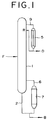
- Fig. 1 is a front view of a distillation column equipped with a condenser and a re-boiler.
- the condenser is supported as connected to the upper part of the straight shell of the distillation column so as to decrease the vapor phase volume of the connecting line and shorten the retention time of the substance under treatment in the connecting line.
- the re-boiler is supported as connected to the lower part of the straight shell so as to decrease the vapor phase volume of the connecting line.
- a vertical heat exchanger may be used as the condenser, a vertical heat exchanger as the re-boiler, and a plate tower as the distillation column as popularly accepted.
- the vapor phase volume of a connecting line 9 is decreased to the fullest possible extent by minimizing the distance between the outlet of a distillation column 1 and the inlet of a condenser 5.
- the connecting line 9 to the condenser (shell-and-tube heat exchanger) 5 is drawn out of the straight shell near the top of the distillation column 1 and supported by the distillation column 1 (Fig. 1 omits illustrating a support for fastening the condenser to the distillation column).
- the connecting member or (inter)connecting line is not particularly limited on account of shape (such factors as radius of curvature, angle of bend, and angle of diversion), it is preferred to shorten the distance of connection with a view to heightening the effect of connection.
- the distillation column and the condenser With a 90° (miter)bend/elbow joint or a short pipe/reducer.
- the connection of the connecting line to the distillation column or to the condenser can be attained by any of the known methods such as, for example, welding or bolt-and-nut fastening through flanges.
- An easily polymerizable matter-containing substance F such as (meth)acrylic acid containing impurities is supplied to the distillation column 1 to effect distillation of (meth)acrylic acid therein.
- the length of the connecting line 9 from the top of the distillation column 1 to the condenser 5 is smaller than heretofore usual, the polymerization of the vapor of the easily polymerizable matter such as (meth)acrylic acid in the connecting line 9 can be decreased. It is naturally necessary that the linear velocity of the vapor in the connecting line 9 be not less than 5 m per second and the retention time of the vapor therein be not more than 3 seconds.
- the liquid as of the (meth)acrylic acid which has been indirectly cooled with a known coolant such as water or a cooling liquid in the condenser 5 is handled as a reflux liquid R or a distillate D.
- a re-boiler 7 is disposed in the lower lateral part of the distillation column 1 using a (inter)connecting line 6.
- the vapor phase volume of the connecting line 6 is decreased to the fullest possible extent by minimizing the distance between the outlet of the re-boiler 7 and the inlet of the distillation column 1.
- the outlet of the re-boiler 7 is connected to the straight shell near the bottom of the distillation column 1 (Fig. 1 omits illustrating a support for fastening the re-boiler to the distillation column).
- the connecting member or connecting line is not particularly limited on account of shape (such factors as radius of curvature, angle of bend, and angle of diversion), it is preferred to shorten the distance of connection with a view to heightening the effect of connection.
- the liquid of the easily polymerizable matter as (meth)acrylic acid which is in the bottom part of the distillation column 1 flows through the connecting line 2 and enters the re-boiler 7.
- the vapor from the liquid re-boiled in the re-boiler 7 passes through the connecting line 6 and enters the vapor phase part of the distillation column 1.
- the connecting line 6 the polymerization of the vapor is prevented or allayed because the linear velocity of the vapor is not less than 5 m per second and the retention time thereof is not more than 3 seconds.
- the bottom stream from the re-boiler 7 is discharged via the connecting line 2 (B).
- the connection of the connecting line to the distillation column or to the re-boiler can be accomplished by any of the known methods such as welding or bolt-and-nut fastening through flanges.
- the distillation column mentioned above is supported by any of the known devices such as a structure (not shown).
- Fig. 2 is a sectional view illustrating a distillation column furnished with a condenser and a re-boiler, both condenser and re-boiler having a plurality of tubes therein.
- the condenser is supported as connected to the upper part of the straight shell of the distillation column to decrease the vapor phase volume of the connecting line and shorten the retention time of the matter under treatment, and a natural circulation type re-boiler is further disposed directly in the lower part of the straight shell of the distillation column.
- the condenser and the distillation column are not particularly limited but allowed to use well-known devices such as a vertical heat exchanger and a plate tower. In the diagram, like members or parts found in Fig.
- the vapor phase volume of the connecting line 9 is decreased to the fullest possible extent by minimizing the distance from the outlet of the distillation column 1 to the inlet of the condenser 5.
- the connecting line 9 to the condenser (shell-and-tube heat exchanger) 5 is drawn out of the straight shell near the top of the distillation column 1 and supported by the distillation column 1 (Fig. 2 omits illustrating a support to be used for supporting the condenser to the distillation column).
- the connecting member is not particularly limited on account of shape (such factors as radius of curvature, angle of bend, and angle of diversion), it is preferred to shorten the distance of connection with a view to heightening the effect.
- the connection of the connecting line to the distillation column or to the condenser can be attained by any of known methods such as welding or bolt-and-but fastening through flanges.
- the easily polymerizable matter-containing substance F such as (meth)acrylic acid containing impurities is supplied to the distillation column 1 and subjected therein to distillation of (meth)acrylic acid.
- the polymerization of the vapor of the easily polymerizable matter such as (meth)acrylic acid in the connecting line 9 can be allayed because the length of the connecting line 9 from the top of the distillation column 1 to the condenser 5 is shorter than heretofore usual. Naturally, it is necessary that the linear velocity of the vapor in the connecting line 9 be not less than 5 m per second and the retention time thereof not more than 3 seconds.
- the liquid as of (meth)acrylic acid cooled indirectly with a known coolant such as water or cooling liquid in the condenser 5 is handled as a reflux liquid R or a distillate D.
- the re-boiler is disposed directly in the lower part of the interior of the distillation column 1.
- the distillation column is a plate column, it is fated to be positioned below the lowest stage in the plate column.
- the re-boiler mentioned above which is directly disposed in the lower part of the distillation column 1 is preferred to be composed of a cylindrical vessel 8 provided on the lateral side thereof with an inlet 14 and an outlet 15 for a heating medium and tightly sealed in the upper and lower parts thereof, a plurality of heat transfer tubes or heating tubes 11 disposed between the upper and lower sides of the cylindrical vessel 8 and provided respectively therein with a vertically piercing hole, a vapor guide 12 disposed above the cylindrical vessel 8 and having a vapor vent 17 opened into the vapor phase part of the distillation column, a loose lid 16 disposed on or above the vapor vent 17, and a down-take 13 disposed in such a manner outside the heating tube 11 as to join the upper and lower parts of the cylindrical vessel 8.
- the easily polymerizable matter-containing substance F such as (meth)acrylic acid containing impurities is supplied to the distillation column 1 and subjected therein to distillation of (meth)acrylic acid.
- the liquid containing (meth)acrylic acid from the bottom of the distillation column 1 is supplied to the heating tube 11 of the re-boiler.
- the liquid passes from the liquid surface positioned above the upper re-boiler tube sheet of the re-boiler through the down-take 13, ascends the interior of the heating tube 11 in a boiling state, and succumbs to natural circulation.
- the vapor guide 12 By allowing the vapor guide 12 to open into the vapor phase part of the distillation column, it is possible not only to shorten the vaporization zone so as to relax the polymerization within the tube but also to increase the amount of the liquid to be circulated, shorten the retention time of the liquid, prevent partial rise of the temperature of (meth)acrylic acid, and preclude the polymerization of the polymerizable matter.
- the vapor formed by the boiling ascends, passes through the vapor guide 12, enters the distillation column 1, and succumbs to the ordinary treatment of distillation.
- the outlet of the heating tube 11 of the re-boiler generally constitutes itself the phase of a vapor-liquid mixture.
- the heating for the boiling mentioned above is effected by introducing a heat medium such as steam through a heat medium inlet 14 and the heat medium spent in exchange of heat is discharged through an outlet 15. Then, the bottom stream is discharged through an outlet 19 (B).
- the linear velocity of the vapor can be set at a level of not less than 5 m per second and the retention time of the vapor at a level of not more than 3 seconds and the polymerization of the vapor of the easily polymerizable matter such as (meth)acrylic acid between the re-boiler and the distillation column 1 can be allayed.
- reference numeral 20 is a plate with a plurality of fine holes, reference numeral 21 an inlet of a coolant such as water, and reference numeral 22 an outlet thereof.
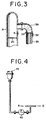
- Fig. 3 is a fragmentary sectional view of another embodiment of the connecting line between the distillation column and the condenser in Fig. 2.
- a (inter)connecting line 39 such as a miter bend is equipped between the distillation column 31 with the plate 20 and the condenser 35 with an outlet 32 of a coolant by means of bolt-and-nut fastening through flanges.
- the inner diameter of the connecting line 39 is substantially identical to that of shell of the condenser 35 from the column 31 to the tube sheet 34 of the condenser 35 in the view point of increasing good distribution of the vapor and preventing the channeling thereof.
- Fig. 4 is a fragmentary front view of another embodiment of pipes between the condenser 45 and the R place of the distillation column in Fig. 2.
- a pump 40 is equipped between the pipe by means of bolt-and-nut fastening through flanges.
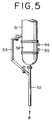
- Fig. 5 is a fragmentary front view of another embodiment of the down-take in Fig. 2.
- another embodiment of a down-take 53 is equipped between the distillation column with a re-boiler 58, which has an inlet 54 and outlet 55, of a heat medium, and the pipe 52 by means of bolt-and-nut fastening through flanges.
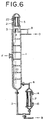
- Fig. 6 is a sectional view of a distillation column such in construction that a condenser is directly disposed in the top of the distillation column and a re-boiler is attached to the lateral lower part of the distillation column, both condenser and re-boiler having a plurality of tubes therein.
- the condenser and the distillation column are not particularly limited but may use well-known devices such as a vertical heat exchanger and a plate column.
- the connection of the distillation column and the condenser can be attained by well-known methods such as welding or bolt-and-nut fastening through flanges.
- like members or parts found in Fig. 1 are represented by like reference numerals. With reference to Fig.
- the vertical shell-and-tube heat exchanger 5 is directly disposed in the top part 3 of the distillation column 1.
- the easily polymerizable matter-containing substance F such as (meth)acrylic acid containing impurities is supplied to the distillation column 1 and subjected therein to distillation of (meth)acrylic acid.
- the vapor of the easily polymerizable matter such as (meth)acrylic acid enters the condenser 5.
- the vapor of the easily polymerizable matter that has entered into the condenser 5 is condensed as indirectly cooled with a well-known coolant such as water or a cooling liquid.
- the liquid resulting from the condensation is received in a pan 4 disposed in the upper part of the distillation column 1, recovered as a reflux liquid R in the distillation column 1, and further processed as occasion demands (D).
- a plate with a plurality of fine holes may be provided between the pan 4 and the condenser 5 in order to avoid the liquid condensed to directly enter the column 1 through the opening of the pan 4.
- the plate may be provided among the inner walls but provided in order to only cover the opening of the pan 4.
- the condenser 5 Since the condenser 5 is directly disposed in the top part 3 of the distillation column 1 and the linear velocity of the vapor is set at a level of not less than 5 m per second and the retention time at a level of not more than 3 second as required, the polymerization of the vapor of the easily polymerizable matter such as (meth)acrylic acid between the distillation column and the condenser 5 can be allayed.
- the re-boiler 7 is disposed in the lower lateral part of the distillation column 1 using a (inter)connecting line.
- the re-boiler is not particularly limited but may use any of the devices well known to the art.
- the vapor phase volume of the connecting line 6 is decreased to the fullest possible extent by minimizing the distance between the outlet of the re-boiler 7 and the inlet of the distillation column 1.
- the outlet of the re-boiler 7 is connected to the straight shell near the bottom of the distillation column 1 (Fig. 6 omits illustrating a support for fastening the re-boiler to the distillation column).
- the connecting member or pipe is not particularly limited on account of shape (such factors as radius of curvature, angle of bend, and angle of diversion), it is preferred to shorten the distance of connection with a view to heightening the effect.
- the connection of the connecting line 6 to the distillation column 1 or to the re-boiler 7 can be effected by such well-known methods as welding or bolt-and-nut fastening through flanges.
- the liquid of the easily polymerizable matter such as (meth)acrylic acid in the bottom part of the distillation column 1 passes through the connecting line 2 and enters the re-boiler 7.
- the vapor of the liquid formed by re-boiling in the re-boiler 7 passes through the connecting line 6 and enters the vapor phase part of the distillation column 1.
- the polymerization of the vapor is prevented or allayed because the linear velocity of the vapor is set at a level of not less than 5 m per second and the retention time thereof at a level of not more than 3 seconds.
- the bottom stream in the re-boiler 7 is discharged via the connecting line 2 (B).
- reference numeral 20 is a plate with a plurality of fine holes, reference numeral 14 an inlet of a heat medium, reference numeral 15 an outlet thereof, reference numeral 21 an inlet of a coolant such as water, and reference numeral 22 an outlet thereof.
- Fig. 7 is a fragmentary sectional view of another embodiment of a (inter)connecting line between the distillation column and the re-boiler in Fig. 6.
- a (inter)connecting line 76 such as a miter bend is equipped between the distillation column 71 with the plate 20 and the re-boiler 77 with an inlet 74 of a heat medium by means of bolt-and-nut fastening through flanges.
- the inner diameter of the connecting line 76 is substantially identical to that of shell of the re-boiler 77 from the column 71 to the tube sheet 78 of the re-boiler 77 in the view point of good distribution of the vapor and preventing the channeling thereof.
- the polymerization of the easily polymerizable matter-containing substance such as (meth)acrylic acid in the connecting line can be effectively prevented as described above.
- the polymerization of (meth)acrylic acid ester can be effectively prevented.
- Acrylic acid was refined by the use of a distillation column measuring 1100 mm in inside diameter and having 50 sieve trays of stainless steel (SUS316) built therein.
- the distillation was performed continuously for one week by feeding a feed liquid composed of 98 wt. % of acrylic acid and 2 wt. % of acetic acid under the conditions of 53.3 hPa-abs (40 mmHg) of column top pressure, 63°C of column top temperature, 120 hPa-abs (90 mmHg) of column bottom pressure, 84°C of column bottom temperature, and 7 of reflux ratio.
- a re-boiler was connected to the distillation column by means of a vapor line and supported to the column by means of a structure (not shown) in the straight shell near the bottom part of the column and a flanged connecting pipe.
- the vapor line opened into the vapor phase part of the distillation column.
- the column was opened and the interior thereof was visually examined, the vapor line of the re-boiler showed no sign of adhesion of a polymer.
- Acrylic acid was refined by the use of a distillation column measuring 1400 mm in inside diameter and having 10 sieve trays of stainless steel built therein. The distillation was performed continuously for three weeks by feeding a feed liquid composed of 99% of acrylic acid and 1% of impurities including the dimer or acrylic acid under the conditions of 46.7 hPa-abs (35 mmHg) of column top pressure, 63°C of column top temperature, and 0.3 of reflux ratio. (At the end of the operation, the acrylic acid at the top thereof had an assay of above 99.95 %).
- a re-boiler was a natural circulation type one provided with a down-take outside the heating tubes and further furnished with a vapor guide opening into the vapor phase part of the column and disposed directly in the distillation column. Then the column was opened and the interior thereof was visually examined, no sign of adhesion of a polymer was recognized.
- the distillation was carried out by following the procedure of Example 1 while having a condenser disposed in the top of a distillation column through flanges. The distillation was continued for two weeks. (At the end of the operation, acrylic acid at the bottom thereof had an assay of 99.95 %). Then the column was opened and the interior thereof was visually examined, the top of the column and the condenser showed no sign of adhesion of a polymer.
- 2-Ethylhexyl acrylate was refined by the use of a distillation column measuring 1200 mm in inside diameter and having 20 sieve trays of stainless steel built therein.
- the distillation was performed continuously for three weeks by feeding a feed liquid composed of 98.5 wt. % of 2-ethylhexyl acrylate and 1.5 wt. % of an impurity having a high boiling point under the conditions of 26.7 hPa-abs (20 mmHg) of column top pressure, 107°C of column top temperature, and 0.4 of reflux ratio.
- a condenser vertical shell-and-tube heat exchanger
- the linear velocity of the vapor in the vapor line was 22 m/s and the retention time thereof was 0.09 second.
- the pressure loss between the top of the column to the condenser was constant during the course of distillation. Then the distillation column was opened and the interior thereof was visually inspected, the surfaces of tubes from the top of the column through the condenser showed no sign of adhesion of a polymer.
- a re-boiler was connected to the distillation column by means of a vapor line and supported to the column by means of a structure (not shown) in the straight shell near the bottom part of the column and a flanged connecting pipe in which the inner diameter of the vapor line was identical to that of the re-boiler.
- the vapor line opened into the vapor phase part of the distillation column.
- the column was opened and the interior thereof was visually examined, the vapor line of the re-boiler showed no sign of adhesion of a polymer.
Landscapes
- Chemical & Material Sciences (AREA)
- Chemical Kinetics & Catalysis (AREA)
- Organic Low-Molecular-Weight Compounds And Preparation Thereof (AREA)
- Vaporization, Distillation, Condensation, Sublimation, And Cold Traps (AREA)
Applications Claiming Priority (2)
| Application Number | Priority Date | Filing Date | Title |
|---|---|---|---|
| JP9789399 | 1999-04-05 | ||
| JP09789399A JP5066309B2 (ja) | 1999-04-05 | 1999-04-05 | 易重合性物質含有物の精製方法 |
Publications (3)
| Publication Number | Publication Date |
|---|---|
| EP1043050A2 true EP1043050A2 (fr) | 2000-10-11 |
| EP1043050A3 EP1043050A3 (fr) | 2001-03-07 |
| EP1043050B1 EP1043050B1 (fr) | 2009-03-04 |
Family
ID=14204439
Family Applications (1)
| Application Number | Title | Priority Date | Filing Date |
|---|---|---|---|
| EP00302234A Expired - Lifetime EP1043050B1 (fr) | 1999-04-05 | 2000-03-20 | Procédé de raffinage d' un matériau contenant une substance polymérisant facilement |
Country Status (5)
| Country | Link |
|---|---|
| US (2) | US6635148B1 (fr) |
| EP (1) | EP1043050B1 (fr) |
| JP (1) | JP5066309B2 (fr) |
| CN (1) | CN100384808C (fr) |
| MY (1) | MY121148A (fr) |
Cited By (5)
| Publication number | Priority date | Publication date | Assignee | Title |
|---|---|---|---|---|
| US6666956B1 (en) * | 1999-02-18 | 2003-12-23 | Nippon Shokubai Co., Ltd. | Method for distilling polymerizable compound or liquid containing polymerizable compound |
| EP1440964A4 (fr) * | 2001-10-09 | 2005-06-22 | Mitsubishi Chem Corp | Procede permettant la production de composes (meth)acryliques et procede de distillation |
| US7014736B2 (en) | 2003-03-18 | 2006-03-21 | Nippon Shokubai Co., Ltd. | Apparatus and process for purification of acrylic acid family |
| US7326323B2 (en) | 2002-12-03 | 2008-02-05 | Rohm And Haas Company | High capacity purification of thermally unstable compounds |
| RU2510286C1 (ru) * | 2013-05-31 | 2014-03-27 | Виктор Владимирович Лобанов | Устройство для фракционирования тяжелых углеводородных фракций |
Families Citing this family (8)
| Publication number | Priority date | Publication date | Assignee | Title |
|---|---|---|---|---|
| US7275038B1 (en) * | 2000-08-18 | 2007-09-25 | The Crawford Group, Inc. | Web enabled business to business operating system for rental car services |
| JP4659988B2 (ja) * | 2001-02-06 | 2011-03-30 | 株式会社日本触媒 | 機器の冷却方法 |
| WO2003018162A1 (fr) | 2001-08-22 | 2003-03-06 | Mitsubishi Chemical Corporation | Materiel de distillation de compose du type en lase de polymerisation |
| US8734618B2 (en) * | 2008-12-08 | 2014-05-27 | Shell Oil Company | Apparatus |
| DE102010010997A1 (de) | 2010-03-10 | 2011-09-15 | Lurgi Gmbh | Verfahren und Vorrichtung zur Destillation von zur Polymerisation neigenden Verbindungen |
| DE102013214765A1 (de) * | 2013-07-29 | 2015-01-29 | Wacker Chemie Ag | Verfahren und Vorrichtung zur destillativen Trennung eines Drei- oder Mehrkomponentengemisches |
| CN107790078B (zh) * | 2017-12-08 | 2024-03-19 | 南京大学 | 一种生产对乙酰氨基酚的装置及工艺 |
| US12233363B2 (en) * | 2021-09-07 | 2025-02-25 | Uop Llc | Vapor distribution system in a concentric reboiler |
Family Cites Families (24)
| Publication number | Priority date | Publication date | Assignee | Title |
|---|---|---|---|---|
| US2341281A (en) * | 1940-11-09 | 1944-02-08 | Lummus Co | Method of and apparatus for condensing vapors |
| BE541274A (fr) * | 1954-09-20 | |||
| GB866421A (en) * | 1958-04-28 | 1961-04-26 | Fumitake Yoshida | Distillation apparatus |
| US3211561A (en) * | 1961-11-15 | 1965-10-12 | Eastman Kodak Co | Diester plasticizers |
| JPS4915153B1 (fr) | 1969-06-06 | 1974-04-12 | ||
| ZA703313B (en) * | 1970-05-18 | 1971-07-28 | Huletts Sugar | Improvements in or relating to evaporators with mixing condensers |
| JPS4862712A (fr) * | 1971-12-07 | 1973-09-01 | ||
| US3988213A (en) * | 1972-09-25 | 1976-10-26 | Nippon Shokubai Kagaku Kogyo Co., Ltd. | Method of distilling vinyl compounds |
| JPS50126605A (fr) * | 1974-03-23 | 1975-10-04 | ||
| JPS5791944A (en) * | 1980-12-01 | 1982-06-08 | Nippon Kayaku Co Ltd | Recovery of methacrolein and/or methacrylic acid, and quenching tower |
| GB8600539D0 (en) * | 1986-01-10 | 1986-02-19 | Foster Wheeler Power Prod | Vapour generator |
| US4773968A (en) * | 1986-12-12 | 1988-09-27 | Enterprise Products Company | N-butane/isobutane fractionation |
| JPS63151329A (ja) * | 1986-12-16 | 1988-06-23 | Osaka Gas Co Ltd | 再生塔塔底液の抜き出し装置 |
| DE3904711A1 (de) * | 1989-02-16 | 1990-08-23 | Krupp Koppers Gmbh | Insbesondere zur trennung von einsatzprodukten mit hoher siedepunktsdifferenz geeignete abtriebskolonne |
| JP2679557B2 (ja) * | 1992-11-12 | 1997-11-19 | 三菱化学株式会社 | メチルイソシアネートの連続的製造法 |
| GB9407257D0 (en) * | 1993-04-22 | 1994-06-08 | Ici Plc | Vaporisation of liquids |
| JP3129105B2 (ja) * | 1994-09-29 | 2001-01-29 | 三菱化学株式会社 | 塩化ビニル系重合体の製造方法 |
| DE19539295A1 (de) | 1995-10-23 | 1997-04-24 | Basf Ag | Verfahren zur kontinuierlichen destillativen Auftrennung von flüssigen Gemischen, die als Hauptbestandteil (Meth)acrylsäure enthalten |
| US5735141A (en) * | 1996-06-07 | 1998-04-07 | The Boc Group, Inc. | Method and apparatus for purifying a substance |
| CA2203352C (fr) * | 1996-06-07 | 2000-08-01 | Walter H. Whitlock | Methode et appareil pour purifier une substance |
| JP4079480B2 (ja) * | 1996-08-20 | 2008-04-23 | 三菱化学株式会社 | (メタ)アクリル酸エステルの製造方法 |
| JP4242964B2 (ja) * | 1999-03-09 | 2009-03-25 | 株式会社日本触媒 | (メタ)アクリル酸および/またはそのエステルの精製方法 |
| MY121525A (en) * | 1999-03-11 | 2006-01-28 | Nippon Catalytic Chem Ind | Shell-and tube heat exchanger and method for inhibiting polymerization in the shell-and-tube heat exchanger |
| DE60033759T2 (de) * | 1999-10-29 | 2007-12-06 | Nippon Shokubai Co. Ltd. | Destillationsapparat und Destillationsmethode |
-
1999
- 1999-04-05 JP JP09789399A patent/JP5066309B2/ja not_active Expired - Lifetime
-
2000
- 2000-03-17 MY MYPI20001055A patent/MY121148A/en unknown
- 2000-03-20 EP EP00302234A patent/EP1043050B1/fr not_active Expired - Lifetime
- 2000-03-29 US US09/537,621 patent/US6635148B1/en not_active Expired - Lifetime
- 2000-04-05 CN CNB001049682A patent/CN100384808C/zh not_active Expired - Lifetime
-
2003
- 2003-08-15 US US10/641,653 patent/US7253314B2/en not_active Expired - Lifetime
Non-Patent Citations (2)
| Title |
|---|
| OBANA H.: "HEAT EXCHANGER DESIGN HANDBOOK (English translation)", 25 January 1974, KOGAKU TOSHO K.K., pages: 1 - 25, XP002905867 |
| OBANA H.: "HEAT EXCHANGER DESIGN HANDBOOK (In Japanese language)", 25 January 1974, KOGAKU TOSHO K.K., ISBN: 4-7692-0028-5, pages: 560 - 575, XP002905866 |
Cited By (7)
| Publication number | Priority date | Publication date | Assignee | Title |
|---|---|---|---|---|
| US6666956B1 (en) * | 1999-02-18 | 2003-12-23 | Nippon Shokubai Co., Ltd. | Method for distilling polymerizable compound or liquid containing polymerizable compound |
| EP1440964A4 (fr) * | 2001-10-09 | 2005-06-22 | Mitsubishi Chem Corp | Procede permettant la production de composes (meth)acryliques et procede de distillation |
| US7368601B2 (en) | 2001-10-09 | 2008-05-06 | Mitsubishi Chemical Corporation | Process for producing (meth)acrylic acids and process for distilling the same |
| US7396957B2 (en) | 2001-10-09 | 2008-07-08 | Mitsubishi Chemical Corporation | Process for producing (meth)acrylic acids and process for distilling the same |
| US7326323B2 (en) | 2002-12-03 | 2008-02-05 | Rohm And Haas Company | High capacity purification of thermally unstable compounds |
| US7014736B2 (en) | 2003-03-18 | 2006-03-21 | Nippon Shokubai Co., Ltd. | Apparatus and process for purification of acrylic acid family |
| RU2510286C1 (ru) * | 2013-05-31 | 2014-03-27 | Виктор Владимирович Лобанов | Устройство для фракционирования тяжелых углеводородных фракций |
Also Published As
| Publication number | Publication date |
|---|---|
| US7253314B2 (en) | 2007-08-07 |
| EP1043050A3 (fr) | 2001-03-07 |
| CN1269351A (zh) | 2000-10-11 |
| CN100384808C (zh) | 2008-04-30 |
| US6635148B1 (en) | 2003-10-21 |
| EP1043050B1 (fr) | 2009-03-04 |
| MY121148A (en) | 2005-12-30 |
| JP5066309B2 (ja) | 2012-11-07 |
| JP2000290226A (ja) | 2000-10-17 |
| US20040050681A1 (en) | 2004-03-18 |
Similar Documents
| Publication | Publication Date | Title |
|---|---|---|
| US6635148B1 (en) | Method for refining easily polymerizable matter-contained substance and apparatus therefor | |
| US7462262B2 (en) | Vertical multitubular heat exchanger and distillation column system including the same | |
| US6409886B1 (en) | Process for inhibiting the polymerization of easily-polymerizable compounds | |
| KR100509449B1 (ko) | 중합용이성 화합물의 취급방법 | |
| EP0046980B1 (fr) | Méthode et appareil de distillation d'un liquide facilement polymérisable | |
| JPS6311921B2 (fr) | ||
| US7014736B2 (en) | Apparatus and process for purification of acrylic acid family | |
| JP4080090B2 (ja) | 易重合性化合物または易重合性化合物含有液の蒸留方法 | |
| JP4575636B2 (ja) | 多管式熱交換器、これを具備した蒸留装置、および熱交換方法 | |
| CN1315773C (zh) | 含(甲基)丙烯酸类单体的流体的精馏分离方法 | |
| US6588450B2 (en) | Storage tank for viscous oil containing easily polymerizable compounds | |
| RU2352379C2 (ru) | Емкость для легко полимеризуемого соединения | |
| JP4437930B2 (ja) | アクリル酸類の蒸留精製方法 | |
| JP5066496B2 (ja) | 易重合性物質含有物の精製方法 | |
| JP4466190B2 (ja) | 易重合性化合物の取り扱い装置及び製造装置 | |
| JP7147567B2 (ja) | (メタ)アクリル酸又はそのエステルの製造方法 | |
| JPS6341441A (ja) | 2−ヒドロキシアルキル(メタ)アクリレ−トの蒸留方法 | |
| JP2005170931A (ja) | 易重合性化合物用の容器 | |
| JP4186459B2 (ja) | 易重合性化合物用の塔設備 | |
| JPH0717705B2 (ja) | 重合体の製造方法 |
Legal Events
| Date | Code | Title | Description |
|---|---|---|---|
| PUAI | Public reference made under article 153(3) epc to a published international application that has entered the european phase |
Free format text: ORIGINAL CODE: 0009012 |
|
| AK | Designated contracting states |
Kind code of ref document: A2 Designated state(s): BE |
|
| AX | Request for extension of the european patent |
Free format text: AL;LT;LV;MK;RO;SI |
|
| PUAL | Search report despatched |
Free format text: ORIGINAL CODE: 0009013 |
|
| AK | Designated contracting states |
Kind code of ref document: A3 Designated state(s): AT BE CH CY DE DK ES FI FR GB GR IE IT LI LU MC NL PT SE |
|
| AX | Request for extension of the european patent |
Free format text: AL;LT;LV;MK;RO;SI |
|
| RIC1 | Information provided on ipc code assigned before grant |
Free format text: 7B 01D 3/14 A, 7B 01D 3/32 B, 7B 01D 5/00 B |
|
| 17P | Request for examination filed |
Effective date: 20010809 |
|
| AKX | Designation fees paid |
Free format text: BE |
|
| TPAD | Observations filed by third parties |
Free format text: ORIGINAL CODE: EPIDOS TIPA |
|
| 17Q | First examination report despatched |
Effective date: 20060922 |
|
| REG | Reference to a national code |
Ref country code: DE Ref legal event code: 8566 |
|
| GRAP | Despatch of communication of intention to grant a patent |
Free format text: ORIGINAL CODE: EPIDOSNIGR1 |
|
| RTI1 | Title (correction) |
Free format text: METHOD FOR REFINING EASILY POLYMERIZABLE MATTER-CONTAINING SUBSTANCE |
|
| GRAS | Grant fee paid |
Free format text: ORIGINAL CODE: EPIDOSNIGR3 |
|
| GRAA | (expected) grant |
Free format text: ORIGINAL CODE: 0009210 |
|
| AK | Designated contracting states |
Kind code of ref document: B1 Designated state(s): BE |
|
| PLBE | No opposition filed within time limit |
Free format text: ORIGINAL CODE: 0009261 |
|
| STAA | Information on the status of an ep patent application or granted ep patent |
Free format text: STATUS: NO OPPOSITION FILED WITHIN TIME LIMIT |
|
| 26N | No opposition filed |
Effective date: 20091207 |
|
| PGFP | Annual fee paid to national office [announced via postgrant information from national office to epo] |
Ref country code: BE Payment date: 20170213 Year of fee payment: 18 |
|
| REG | Reference to a national code |
Ref country code: BE Ref legal event code: MM Effective date: 20180331 |
|
| PG25 | Lapsed in a contracting state [announced via postgrant information from national office to epo] |
Ref country code: BE Free format text: LAPSE BECAUSE OF NON-PAYMENT OF DUE FEES Effective date: 20180331 |