EP1043075B1 - Einen gleichmässigen Strahl abgebende Düse für Versenkregner - Google Patents
Einen gleichmässigen Strahl abgebende Düse für Versenkregner Download PDFInfo
- Publication number
- EP1043075B1 EP1043075B1 EP00201228A EP00201228A EP1043075B1 EP 1043075 B1 EP1043075 B1 EP 1043075B1 EP 00201228 A EP00201228 A EP 00201228A EP 00201228 A EP00201228 A EP 00201228A EP 1043075 B1 EP1043075 B1 EP 1043075B1
- Authority
- EP
- European Patent Office
- Prior art keywords
- spray
- main body
- water
- sprinkler
- ring nut
- Prior art date
- Legal status (The legal status is an assumption and is not a legal conclusion. Google has not performed a legal analysis and makes no representation as to the accuracy of the status listed.)
- Expired - Lifetime
Links
- 239000007921 spray Substances 0.000 title claims abstract description 36
- XLYOFNOQVPJJNP-UHFFFAOYSA-N water Substances O XLYOFNOQVPJJNP-UHFFFAOYSA-N 0.000 claims abstract description 23
- 230000015572 biosynthetic process Effects 0.000 claims abstract description 7
- 238000009825 accumulation Methods 0.000 claims abstract description 5
- 230000006835 compression Effects 0.000 claims abstract description 4
- 238000007906 compression Methods 0.000 claims abstract description 4
- 239000000463 material Substances 0.000 description 1
- 239000002184 metal Substances 0.000 description 1
- 238000007789 sealing Methods 0.000 description 1
- 229910001220 stainless steel Inorganic materials 0.000 description 1
- 239000010935 stainless steel Substances 0.000 description 1
Images


Classifications
-
- B—PERFORMING OPERATIONS; TRANSPORTING
- B05—SPRAYING OR ATOMISING IN GENERAL; APPLYING FLUENT MATERIALS TO SURFACES, IN GENERAL
- B05B—SPRAYING APPARATUS; ATOMISING APPARATUS; NOZZLES
- B05B1/00—Nozzles, spray heads or other outlets, with or without auxiliary devices such as valves, heating means
- B05B1/30—Nozzles, spray heads or other outlets, with or without auxiliary devices such as valves, heating means designed to control volume of flow, e.g. with adjustable passages
- B05B1/32—Nozzles, spray heads or other outlets, with or without auxiliary devices such as valves, heating means designed to control volume of flow, e.g. with adjustable passages in which a valve member forms part of the outlet opening
-
- B—PERFORMING OPERATIONS; TRANSPORTING
- B05—SPRAYING OR ATOMISING IN GENERAL; APPLYING FLUENT MATERIALS TO SURFACES, IN GENERAL
- B05B—SPRAYING APPARATUS; ATOMISING APPARATUS; NOZZLES
- B05B1/00—Nozzles, spray heads or other outlets, with or without auxiliary devices such as valves, heating means
- B05B1/26—Nozzles, spray heads or other outlets, with or without auxiliary devices such as valves, heating means with means for mechanically breaking-up or deflecting the jet after discharge, e.g. with fixed deflectors; Breaking-up the discharged liquid or other fluent material by impinging jets
- B05B1/262—Nozzles, spray heads or other outlets, with or without auxiliary devices such as valves, heating means with means for mechanically breaking-up or deflecting the jet after discharge, e.g. with fixed deflectors; Breaking-up the discharged liquid or other fluent material by impinging jets with fixed deflectors
-
- B—PERFORMING OPERATIONS; TRANSPORTING
- B05—SPRAYING OR ATOMISING IN GENERAL; APPLYING FLUENT MATERIALS TO SURFACES, IN GENERAL
- B05B—SPRAYING APPARATUS; ATOMISING APPARATUS; NOZZLES
- B05B1/00—Nozzles, spray heads or other outlets, with or without auxiliary devices such as valves, heating means
- B05B1/30—Nozzles, spray heads or other outlets, with or without auxiliary devices such as valves, heating means designed to control volume of flow, e.g. with adjustable passages
- B05B1/3033—Nozzles, spray heads or other outlets, with or without auxiliary devices such as valves, heating means designed to control volume of flow, e.g. with adjustable passages the control being effected by relative coaxial longitudinal movement of the controlling element and the spray head
- B05B1/304—Nozzles, spray heads or other outlets, with or without auxiliary devices such as valves, heating means designed to control volume of flow, e.g. with adjustable passages the control being effected by relative coaxial longitudinal movement of the controlling element and the spray head the controlling element being a lift valve
-
- B—PERFORMING OPERATIONS; TRANSPORTING
- B05—SPRAYING OR ATOMISING IN GENERAL; APPLYING FLUENT MATERIALS TO SURFACES, IN GENERAL
- B05B—SPRAYING APPARATUS; ATOMISING APPARATUS; NOZZLES
- B05B15/00—Details of spraying plant or spraying apparatus not otherwise provided for; Accessories
- B05B15/70—Arrangements for moving spray heads automatically to or from the working position
- B05B15/72—Arrangements for moving spray heads automatically to or from the working position using hydraulic or pneumatic means
- B05B15/74—Arrangements for moving spray heads automatically to or from the working position using hydraulic or pneumatic means driven by the discharged fluid
-
- Y—GENERAL TAGGING OF NEW TECHNOLOGICAL DEVELOPMENTS; GENERAL TAGGING OF CROSS-SECTIONAL TECHNOLOGIES SPANNING OVER SEVERAL SECTIONS OF THE IPC; TECHNICAL SUBJECTS COVERED BY FORMER USPC CROSS-REFERENCE ART COLLECTIONS [XRACs] AND DIGESTS
- Y10—TECHNICAL SUBJECTS COVERED BY FORMER USPC
- Y10S—TECHNICAL SUBJECTS COVERED BY FORMER USPC CROSS-REFERENCE ART COLLECTIONS [XRACs] AND DIGESTS
- Y10S239/00—Fluid sprinkling, spraying, and diffusing
- Y10S239/01—Pattern sprinkler
Definitions
- the present invention concerns a spray nozzle for pop-up underground sprinkler.
- underground sprinklers or pop-up sprinklers deliver water at a nozzle fixed to the mobile part of the sprinkler and therefore subject to the characteristic up and down movement of sprinklers of that type.
- a form of nozzle currently in use provides for a fixed main body that is suitable to receive the water flow coming from the sprinkler and to deliver it toward the outside under form of pre-established rate spray and a revolving ring nut associated with the aforesaid main body in order to allow the adjustment of the spray angle.
- the main body is made up of an annular lower portion that is fixable to the upper end of the mobile part of the sprinkler and communicates with the orifice for the output of the same, an intermediate cross wall provided with a distribution of holes for the flow of water, an upper annular portion, a hub portion placed coaxially inside said upper annular portion and axially bearing a screw for adjusting the length of the spray, and a covering cap that is fixed over said hub portion.
- the revolving ring nut is in turn made up of a annular wall that is arranged around and threadedly engaged with said upper annular portion of the main body and of an upper cross wall that surrounds said hub portion while leaving around it an annular passage for the outflow of water from the area defined between said hub portion and said upper annular portion of the main body and it is in addition interposed between the top of said annular upper portion and said covering cap of the main body in order to define with the latter an adjustable radial flow for the formation and the outflow of a spray of water having adjustable angle.
- a spray nozzle comprising these features has been published in US 5 556 036.
- the present invention aims at realising a spray nozzle for underground sprinklers of the pop-up type that has some advantageous aspects as regards the ones currently known of the aforesaid type.
- a nozzle in first place is characterized in that the upper cross wall of the revolving ring nut has a bottom cavity shaped as a scroll that defines an accumulation chamber in which the flow of water in the area comprised between the hub portion and the upper annular portion of the main body is subject to compression for the formation of a uniform output spray at said adjustable radial passage.
- the lower surface of the covering cap of the nozzle has a short discontinuity in radial direction that allows to break and to deviate a part of the spray in order to have the water reach also areas near the sprinkler.
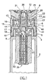
- a spray nozzle 1 is shown as fixed to the upper end of the mobile part 2 of a pop-up underground sprinkler.
- the nozzle 1 comprises a main body 3 that is made up of a lower annular portion 4, an intermediate cross wall 5, an upper annular portion 6, a hub portion 7 and a covering cap 8.
- the lower annular portion 4 is destined to fixing to the mobile part of the sprinkler and to such purpose it is provided with notches 9 on the bottom that are suitable to cooperate with appropriate teeth of the aforesaid mobile part (not shown in the drawing) in order to prevent the rotation of the head during the steps of positioning of the sprinkler and of adjustment of the spray.
- the aforesaid lower annular portion 4 is in addition provided with an annular knurling 10 ( Figures 2 and 4).
- the intermediate cross wall 5 is traversed by a circumferencial distribution of conic holes 11 for the flow of the water coming from the sprinkler.
- the hub portion 7 extends axially toward the top from the intermediate cross wall 5 and bears the covering cap 8 on the top, that in turn has a shape flared toward the top and is provided with lightening holes 12 ( Figures 1-3).
- the upper annular portion 6 has an inside surface 13 flared toward the top and an external cylindrical surface 14 with which there is turningly engaged through a short-pitch (e.g. 1.5 mm) thread 40 an externally knurled annular wall 16 of an adjustment ring nut 15 that has on the bottom a hydraulic sealing ring 41 and an annular sequence of inside teeth 17 that engage with corresponding external teeth 18 of the lower annular portion 4 in order to keep the ring nut 15 in the desired angular position.
- a short-pitch e.g. 1.5 mm
- the ring nut 15 is provided with an upper cross wall 19 that surrounds the hub portion 7 (Fig. 1) thus leaving around it an annular passage 20 for the outflow of the water from the containment area 21 defined between the hub portion 7 and the upper annular portion 6 of the main body 3.
- the aforesaid upper cross wall 19 of the ring nut 15 is in addition interposed between the top of the upper annular portion 6 of the main body 3 and the covering cap 8, in order to define with the latter an adjustable radial passage 22 that is shaped as a scroll for the formation and the outflow of a spray of water with adjustable angle.
- the upper cross wall 19 of the ring nut 15 has a cavity 27 on the bottom shaped as a scroll that functions as a chamber for the accumulation and uniformation of the spray for the water that is contained in the above mentioned area 21.
- nozzle 1 provides for a screw 29 for the adjustment of the length of the spray, that is made up of a head 30 and of a threaded shank 31, both of metal, preferably of stainless steel.
- the head 30 of the screw 29 is positioned inside the nozzle 1 and in such a way so as to extend in the output cone 32 of the filter 36 of the sprinkler, which is made, as an example, by a rigid grid-like internal part 37 and by an external part 33 in reticular spongy material (for example of the type disclosed in EP-A-0860190), and is provided with a central cavity 34 with hexagonal section, that is suitable to receive a setscrew wrench for the fixing of the screw 29 inside the hub portion 7 of the nozzle 1.
- the threaded shank 31 of the same screw instead projects outside of the covering cap 8 of the nozzle 1 and has a hexagonal cavity 35 that is in turn accessible from the outside ( Figures 1-3), that is axially lined up with the cavity 34.
- the cavity 35 is suitable to receive a setscrew wrench for the adjustment of the axial position of the screw 29 as regards the output cone of the filter of the sprinkler and the consequent adjustment of the length of the output water spray.
- the two cavities 34 and 35 have identical shape and identical dimensions, so that they can receive an identical setscrew wrench.
- the flow of water coming from the sprinkler flows through the conic holes 11 of the intermediate cross wall 5 of the nozzle 1, it enters the area 21 defined above the same wall and finally goes out through the annular passage 20 and the passage shaped as a scroll 22 thus forming a spray that is made uniform by the compression action exerted by the accumulation chamber 27.
- the presence of the radial discontinuity 28 in the lower surface of the covering cap 8 allows to deviate part of the water spray in such a way so as to allow it to water even zones very near to the sprinkler.
- the spray angle is adjustable by rotation of the ring nut 15, that by modifying the mutual position of the facing scroll-shaped surface of the ring nut 15 and of the covering cap 8 modifies the configuration of the output passage of the spray correspondingly and therefore the angle of the same.
- the length of the spray is instead adjustable by modifying the axial position of the adjusting screw 29 through the adjustment cavity 35.
Landscapes
- Nozzles (AREA)
- Earth Drilling (AREA)
Claims (3)
- Sprühdüse für hochschnellende unterirdische Sprinkler mit einem festen Hauptkörper (3), der geeignet ist, den Wasserfluss von einem Sprinkler aufzunehmen und ihn in Richtung zur Außenseite mit einer zuvor eingerichteten Sprührate zu liefern, und mit einer sich drehenden Ringmutter (15), die zu dem zuvor angegebenen Hauptkörper gehört, um die Einstellung des Sprühwinkels zuzulassen, wobei der Hauptkörper (3) einen ringförmigen unteren Teil (4) aufweist, der am oberen Ende des mobilen Teils (2) eines Sprinklers fixierbar ist und mit der Ausgangsöffnung desselben kommuniziert, eine dazwischenliegende Querwand (5), die mit einer Verteilung von Löchern für den Fluss des Wassers versehen ist, einen oberen ringförmigen Teil (6), einen Nabenteil (7), der koaxial innerhalb des oberen ringförmigen Teils (6) und einer Abdeckkappe (8), die am Nabenteil (7) fixiert ist, angeordnet ist, wobei die Ringmutter (15) wiederum aus einer ringförmigen Wand (16) hergestellt ist, die drehbar in Eingriff mit dem oberen ringförmigen Teil (6) des Hauptkörpers (3) in Eingriff steht, und aus einer oberen Querwand (19), die den Nabenteil (7) umgibt, um dadurch um ihn einen ringförmigen Durchgang (20) für den Überlauf von Wasser von einem Bereich (21) zu lassen, der zwischen dem Nabenteil (7) und dem oberen ringförmigen Teil (6) des Hauptkörpers (3) definiert ist, und wobei die Querwand (19) weiterhin zwischen dem oberen Ende des ringförmigen oberen Teils (6) und der Abdeckkappe (8) des Hauptkörpers (3) angeordnet ist, um mit der letzteren einen einstellbaren radialen Durchgang (22) für die Bildung und den Überlauf eines Sprühens von Wasser mit einem einstellbaren Winkel zu definieren, dadurch gekennzeichnet, dass die obere Querwand (19) der sich drehenden Ringmutter (15) einen unteren Hohlraum (27) hat, der als Spirale bzw. Ablauf geformt ist, die bzw. der eine Akkumulationskammer definiert, in welcher der Fluss von Wasser in dem Bereich (21), der zwischen dem Nabenteil (7) und dem oberen ringförmigen Teil (6) des Hauptkörpers (3) umfasst ist, für die Bildung eines einheitlichen Ausgangssprühens bei dem einstellbaren radialen Durchgang (22) einer Kompression unterzogen wird.
- Sprühdüse nach Anspruch 1, dadurch gekennzeichnet, dass die untere Oberfläche (25) der Abdeckkappe (8) eine kurze Diskontinuität (28) in einer radialen Richtung hat, die zulässt, einen Teil des Sprühens zu unterbrechen und abweichen zu lassen, um das Wasser auch Bereiche nahe dem Sprinkler erreichen zu lassen.
- Sprühdüse nach Anspruch 1, dadurch gekennzeichnet, dass sie eine Schraube (29) für die Einstellung der Länge des Sprühens aufweist, wobei die Schraube (29) einen Kopf (30) aufweist, der sich in der Ausgangsöffnung des Sprinklers erstreckt, und einen mit einem Gewinde versehenen Schaft (31), der in den Nabenteil (7) des Hauptkörpers (3) der Düse (1) geschraubt ist, wobei der Kopf (30) und der Schaft (31) mit identischen Hohlräumen (34, 35) für einen Einstell-Schraubenschlüssel versehen sind, die jeweils mit demselben Arbeitswerkzeug für das Fixieren und das Einstellen bzw. Justieren der Schraube (29) in Eingriff bringbar sind.
Applications Claiming Priority (2)
| Application Number | Priority Date | Filing Date | Title |
|---|---|---|---|
| ITMI990710 | 1999-04-07 | ||
| IT1999MI000710A IT1311912B1 (it) | 1999-04-07 | 1999-04-07 | Testina di erogazione per irrigatore sotterraneo a scomparsa. |
Publications (2)
| Publication Number | Publication Date |
|---|---|
| EP1043075A1 EP1043075A1 (de) | 2000-10-11 |
| EP1043075B1 true EP1043075B1 (de) | 2003-07-02 |
Family
ID=11382608
Family Applications (1)
| Application Number | Title | Priority Date | Filing Date |
|---|---|---|---|
| EP00201228A Expired - Lifetime EP1043075B1 (de) | 1999-04-07 | 2000-04-04 | Einen gleichmässigen Strahl abgebende Düse für Versenkregner |
Country Status (7)
| Country | Link |
|---|---|
| US (1) | US6264117B1 (de) |
| EP (1) | EP1043075B1 (de) |
| AT (1) | ATE244073T1 (de) |
| AU (1) | AU761375B2 (de) |
| DE (1) | DE60003600T2 (de) |
| ES (1) | ES2201996T3 (de) |
| IT (1) | IT1311912B1 (de) |
Cited By (5)
| Publication number | Priority date | Publication date | Assignee | Title |
|---|---|---|---|---|
| US8783582B2 (en) | 2010-04-09 | 2014-07-22 | Rain Bird Corporation | Adjustable arc irrigation sprinkler nozzle configured for positive indexing |
| US9079202B2 (en) | 2012-06-13 | 2015-07-14 | Rain Bird Corporation | Rotary variable arc nozzle |
| US9314952B2 (en) | 2013-03-14 | 2016-04-19 | Rain Bird Corporation | Irrigation spray nozzle and mold assembly and method of forming nozzle |
| US9427751B2 (en) | 2010-04-09 | 2016-08-30 | Rain Bird Corporation | Irrigation sprinkler nozzle having deflector with micro-ramps |
| US9504209B2 (en) | 2010-04-09 | 2016-11-29 | Rain Bird Corporation | Irrigation sprinkler nozzle |
Families Citing this family (33)
| Publication number | Priority date | Publication date | Assignee | Title |
|---|---|---|---|---|
| IT1316664B1 (it) | 2000-02-24 | 2003-04-24 | Claber Spa | Testina di erogazione multigetto ad elementi controrotanti perirrigatore sotterraneo a scomparsa |
| US6443372B1 (en) * | 2000-12-12 | 2002-09-03 | Tsao-Hui Hsu | Adjustable sprinkler nozzle |
| US6834816B2 (en) * | 2001-07-25 | 2004-12-28 | Carl L. C. Kah, Jr. | Selected range arc settable spray nozzle with pre-set proportional connected upstream flow throttling |
| US6921029B2 (en) * | 2001-11-28 | 2005-07-26 | Rain Bird Corporation | Method and apparatus for reducing the precipitation rate of an irrigation sprinkler |
| DE10202539A1 (de) * | 2002-01-24 | 2003-08-21 | Heinz Kern | Spritzdüse für Beregnungsanlagen |
| US20050194464A1 (en) * | 2004-03-08 | 2005-09-08 | Kenneth Bruninga | Adjustable sprinkler |
| US7726587B2 (en) * | 2005-05-23 | 2010-06-01 | Kevin Markley | Rotary irrigation sprinkler nozzle |
| US8651400B2 (en) | 2007-01-12 | 2014-02-18 | Rain Bird Corporation | Variable arc nozzle |
| US7703706B2 (en) * | 2007-01-12 | 2010-04-27 | Rain Bird Corporation | Variable arc nozzle |
| US8006919B2 (en) * | 2007-09-14 | 2011-08-30 | The Toro Company | Sprinkler with dual shafts |
| USD593182S1 (en) * | 2008-07-31 | 2009-05-26 | Hunter Industries, Inc. | Triple orifice sprinkler nozzle |
| US8074897B2 (en) * | 2008-10-09 | 2011-12-13 | Rain Bird Corporation | Sprinkler with variable arc and flow rate |
| DE102009019932B4 (de) | 2009-05-05 | 2019-10-24 | Husqvarna Ab | Deflektor für eine Düseneinheit eines Regners |
| US8925837B2 (en) | 2009-05-29 | 2015-01-06 | Rain Bird Corporation | Sprinkler with variable arc and flow rate and method |
| US8695900B2 (en) * | 2009-05-29 | 2014-04-15 | Rain Bird Corporation | Sprinkler with variable arc and flow rate and method |
| US8272583B2 (en) | 2009-05-29 | 2012-09-25 | Rain Bird Corporation | Sprinkler with variable arc and flow rate and method |
| US9155926B2 (en) * | 2009-10-13 | 2015-10-13 | Thomas E. Mason | Drain nozzle |
| CN101773884B (zh) * | 2009-12-31 | 2012-02-08 | 广东联塑科技实业有限公司 | 一种黏性埋地喷头的驱动装置 |
| AU2011227742B2 (en) * | 2010-03-17 | 2016-08-04 | Tyco Fire Products Lp | Industrial floor nozzle and fire fighting system |
| USD669964S1 (en) * | 2010-11-15 | 2012-10-30 | Rain Bird Corporation | Irrigation housing component |
| US9174227B2 (en) | 2012-06-14 | 2015-11-03 | Rain Bird Corporation | Irrigation sprinkler nozzle |
| US9327297B2 (en) | 2012-07-27 | 2016-05-03 | Rain Bird Corporation | Rotary nozzle |
| US9295998B2 (en) | 2012-07-27 | 2016-03-29 | Rain Bird Corporation | Rotary nozzle |
| EP2907580B1 (de) | 2014-02-05 | 2017-01-04 | Claber S.P.A. | Ausgabekopf mit neuer durchflussbasierter Verstelleinheit für einen versenkbaren unterirdischen Sprinkler |
| US10322423B2 (en) | 2016-11-22 | 2019-06-18 | Rain Bird Corporation | Rotary nozzle |
| US10232388B2 (en) * | 2017-03-08 | 2019-03-19 | NaanDanJain Irrigation Ltd. | Multiple orientation rotatable sprinkler |
| US11154877B2 (en) | 2017-03-29 | 2021-10-26 | Rain Bird Corporation | Rotary strip nozzles |
| WO2020112632A1 (en) * | 2018-11-26 | 2020-06-04 | Minimax Viking Research & Development Gmbh | Fire suppression system and method for a helicopter landing pad |
| US11059056B2 (en) | 2019-02-28 | 2021-07-13 | Rain Bird Corporation | Rotary strip nozzles and deflectors |
| US11406999B2 (en) | 2019-05-10 | 2022-08-09 | Rain Bird Corporation | Irrigation nozzle with one or more grit vents |
| US11933417B2 (en) | 2019-09-27 | 2024-03-19 | Rain Bird Corporation | Irrigation sprinkler service valve |
| US11247219B2 (en) | 2019-11-22 | 2022-02-15 | Rain Bird Corporation | Reduced precipitation rate nozzle |
| US12030072B2 (en) | 2020-11-16 | 2024-07-09 | Rain Bird Corporation | Pressure regulation device and method for irrigation sprinklers |
Family Cites Families (10)
| Publication number | Priority date | Publication date | Assignee | Title |
|---|---|---|---|---|
| US5226602A (en) | 1989-09-13 | 1993-07-13 | The Toro Company | Adjustable radius sprinkler nozzle |
| US5360167A (en) * | 1989-09-13 | 1994-11-01 | The Toro Company | Adjustable radius sprinkler nozzle |
| US5148990A (en) * | 1990-06-29 | 1992-09-22 | Kah Jr Carl L C | Adjustable arc spray and rotary stream sprinkler |
| IL105335A (en) * | 1990-12-05 | 1996-10-31 | Lego Lemelstrich Ltd | Static sector-type water sprinkler |
| IL96547A (en) * | 1990-12-05 | 1994-04-12 | Lego Lemelstrich Ltd | Static sector-type water sprinkler |
| US5556036A (en) | 1994-10-26 | 1996-09-17 | Hunter Industries Incorporated | Adjustable arc spinkler nozzle |
| US5642861A (en) * | 1995-09-01 | 1997-07-01 | Camsco Manufacturing Corp. | Plastic spray nozzle with improved distribution |
| IT1290333B1 (it) | 1997-02-17 | 1998-10-22 | Claber Spa | Elemento filtrante per raccordi per tubazioni flessibili di impianti d'irrigazione,particolarmente ma non esclusivamente per giardini o |
| US6019295A (en) * | 1997-05-21 | 2000-02-01 | The Toro Company | Adjustable arc fixed spray sprinkler nozzle |
| US6145758A (en) * | 1999-08-16 | 2000-11-14 | Anthony Manufacturing Corp. | Variable arc spray nozzle |
-
1999
- 1999-04-07 IT IT1999MI000710A patent/IT1311912B1/it active
-
2000
- 2000-04-03 US US09/541,293 patent/US6264117B1/en not_active Expired - Lifetime
- 2000-04-03 AU AU25224/00A patent/AU761375B2/en not_active Ceased
- 2000-04-04 AT AT00201228T patent/ATE244073T1/de not_active IP Right Cessation
- 2000-04-04 EP EP00201228A patent/EP1043075B1/de not_active Expired - Lifetime
- 2000-04-04 ES ES00201228T patent/ES2201996T3/es not_active Expired - Lifetime
- 2000-04-04 DE DE60003600T patent/DE60003600T2/de not_active Expired - Lifetime
Cited By (5)
| Publication number | Priority date | Publication date | Assignee | Title |
|---|---|---|---|---|
| US8783582B2 (en) | 2010-04-09 | 2014-07-22 | Rain Bird Corporation | Adjustable arc irrigation sprinkler nozzle configured for positive indexing |
| US9427751B2 (en) | 2010-04-09 | 2016-08-30 | Rain Bird Corporation | Irrigation sprinkler nozzle having deflector with micro-ramps |
| US9504209B2 (en) | 2010-04-09 | 2016-11-29 | Rain Bird Corporation | Irrigation sprinkler nozzle |
| US9079202B2 (en) | 2012-06-13 | 2015-07-14 | Rain Bird Corporation | Rotary variable arc nozzle |
| US9314952B2 (en) | 2013-03-14 | 2016-04-19 | Rain Bird Corporation | Irrigation spray nozzle and mold assembly and method of forming nozzle |
Also Published As
| Publication number | Publication date |
|---|---|
| AU2522400A (en) | 2000-10-12 |
| AU761375B2 (en) | 2003-06-05 |
| IT1311912B1 (it) | 2002-03-20 |
| EP1043075A1 (de) | 2000-10-11 |
| ATE244073T1 (de) | 2003-07-15 |
| DE60003600T2 (de) | 2004-06-03 |
| ITMI990710A1 (it) | 2000-10-07 |
| ES2201996T3 (es) | 2004-04-01 |
| DE60003600D1 (de) | 2003-08-07 |
| US6264117B1 (en) | 2001-07-24 |
Similar Documents
| Publication | Publication Date | Title |
|---|---|---|
| US6264117B1 (en) | Spray nozzle for pop-up underground sprinkler | |
| US7156322B1 (en) | Irrigation sprinkler unit with cycling flow rate | |
| US6464151B1 (en) | Flow volume adjustment device for irrigation sprinkler heads | |
| US5348228A (en) | Water sprayer with flow rate control | |
| US4752031A (en) | Bubbler assembly | |
| US4944456A (en) | Rotary sprinkler | |
| US20120223162A1 (en) | Rotating sprinkler head valve | |
| US6834816B2 (en) | Selected range arc settable spray nozzle with pre-set proportional connected upstream flow throttling | |
| US7913932B2 (en) | Sprinkler having a multifunctional protective hood | |
| US5205491A (en) | Static sector-type water sprinkler | |
| US20070119981A1 (en) | Pressure chamber nozzle assembly | |
| CA2195503A1 (en) | Pump sprayer nozzle for producing a solid spray pattern | |
| CN2344091Y (zh) | 可调式喷头 | |
| US4284241A (en) | Spray nozzle for distribution of liquid which is intended to be affixed transversely to the wall of a conduit | |
| US3711031A (en) | Valve button | |
| US5004161A (en) | Adjustable miniature watering device | |
| US5833143A (en) | Garden hose nozzle | |
| US4042174A (en) | Nozzle adapter | |
| JP3148244B2 (ja) | シャワーヘッド | |
| ITMI20120090U1 (it) | Pistola per verniciatura a spruzzo. | |
| KR200261017Y1 (ko) | 살수용분무기의분사노즐 | |
| JP3200702B2 (ja) | 散布装置 | |
| JP2697086B2 (ja) | 散水ノズル | |
| US20070138325A1 (en) | Spraying and atomization device of a saline mixture | |
| WO2024258369A1 (en) | Irrigation spray head screw with adjustable auto sprinkler control |
Legal Events
| Date | Code | Title | Description |
|---|---|---|---|
| PUAI | Public reference made under article 153(3) epc to a published international application that has entered the european phase |
Free format text: ORIGINAL CODE: 0009012 |
|
| AK | Designated contracting states |
Kind code of ref document: A1 Designated state(s): AT BE CH CY DE DK ES FI FR GB GR IE IT LI LU MC NL PT SE |
|
| AX | Request for extension of the european patent |
Free format text: AL;LT;LV;MK;RO;SI |
|
| 17P | Request for examination filed |
Effective date: 20010327 |
|
| AKX | Designation fees paid |
Free format text: AT BE CH CY DE DK ES FI FR GB GR IE IT LI LU MC NL PT SE |
|
| GRAH | Despatch of communication of intention to grant a patent |
Free format text: ORIGINAL CODE: EPIDOS IGRA |
|
| GRAH | Despatch of communication of intention to grant a patent |
Free format text: ORIGINAL CODE: EPIDOS IGRA |
|
| GRAA | (expected) grant |
Free format text: ORIGINAL CODE: 0009210 |
|
| AK | Designated contracting states |
Designated state(s): AT BE CH CY DE DK ES FI FR GB GR IE IT LI LU MC NL PT SE |
|
| PG25 | Lapsed in a contracting state [announced via postgrant information from national office to epo] |
Ref country code: AT Free format text: LAPSE BECAUSE OF FAILURE TO SUBMIT A TRANSLATION OF THE DESCRIPTION OR TO PAY THE FEE WITHIN THE PRESCRIBED TIME-LIMIT Effective date: 20030702 Ref country code: NL Free format text: LAPSE BECAUSE OF FAILURE TO SUBMIT A TRANSLATION OF THE DESCRIPTION OR TO PAY THE FEE WITHIN THE PRESCRIBED TIME-LIMIT Effective date: 20030702 Ref country code: CH Free format text: LAPSE BECAUSE OF FAILURE TO SUBMIT A TRANSLATION OF THE DESCRIPTION OR TO PAY THE FEE WITHIN THE PRESCRIBED TIME-LIMIT Effective date: 20030702 Ref country code: FI Free format text: LAPSE BECAUSE OF FAILURE TO SUBMIT A TRANSLATION OF THE DESCRIPTION OR TO PAY THE FEE WITHIN THE PRESCRIBED TIME-LIMIT Effective date: 20030702 Ref country code: LI Free format text: LAPSE BECAUSE OF FAILURE TO SUBMIT A TRANSLATION OF THE DESCRIPTION OR TO PAY THE FEE WITHIN THE PRESCRIBED TIME-LIMIT Effective date: 20030702 Ref country code: CY Free format text: LAPSE BECAUSE OF FAILURE TO SUBMIT A TRANSLATION OF THE DESCRIPTION OR TO PAY THE FEE WITHIN THE PRESCRIBED TIME-LIMIT Effective date: 20030702 |
|
| REG | Reference to a national code |
Ref country code: GB Ref legal event code: FG4D |
|
| REG | Reference to a national code |
Ref country code: CH Ref legal event code: EP |
|
| REG | Reference to a national code |
Ref country code: IE Ref legal event code: FG4D |
|
| REF | Corresponds to: |
Ref document number: 60003600 Country of ref document: DE Date of ref document: 20030807 Kind code of ref document: P |
|
| PG25 | Lapsed in a contracting state [announced via postgrant information from national office to epo] |
Ref country code: DK Free format text: LAPSE BECAUSE OF FAILURE TO SUBMIT A TRANSLATION OF THE DESCRIPTION OR TO PAY THE FEE WITHIN THE PRESCRIBED TIME-LIMIT Effective date: 20031002 Ref country code: SE Free format text: LAPSE BECAUSE OF FAILURE TO SUBMIT A TRANSLATION OF THE DESCRIPTION OR TO PAY THE FEE WITHIN THE PRESCRIBED TIME-LIMIT Effective date: 20031002 Ref country code: PT Free format text: LAPSE BECAUSE OF FAILURE TO SUBMIT A TRANSLATION OF THE DESCRIPTION OR TO PAY THE FEE WITHIN THE PRESCRIBED TIME-LIMIT Effective date: 20031002 |
|
| REG | Reference to a national code |
Ref country code: GR Ref legal event code: EP Ref document number: 20030403970 Country of ref document: GR |
|
| NLV1 | Nl: lapsed or annulled due to failure to fulfill the requirements of art. 29p and 29m of the patents act | ||
| REG | Reference to a national code |
Ref country code: CH Ref legal event code: PL |
|
| REG | Reference to a national code |
Ref country code: ES Ref legal event code: FG2A Ref document number: 2201996 Country of ref document: ES Kind code of ref document: T3 |
|
| PG25 | Lapsed in a contracting state [announced via postgrant information from national office to epo] |
Ref country code: GB Free format text: LAPSE BECAUSE OF NON-PAYMENT OF DUE FEES Effective date: 20040404 Ref country code: LU Free format text: LAPSE BECAUSE OF NON-PAYMENT OF DUE FEES Effective date: 20040404 |
|
| PG25 | Lapsed in a contracting state [announced via postgrant information from national office to epo] |
Ref country code: IE Free format text: LAPSE BECAUSE OF NON-PAYMENT OF DUE FEES Effective date: 20040405 |
|
| ET | Fr: translation filed | ||
| PG25 | Lapsed in a contracting state [announced via postgrant information from national office to epo] |
Ref country code: MC Free format text: LAPSE BECAUSE OF NON-PAYMENT OF DUE FEES Effective date: 20040430 Ref country code: BE Free format text: LAPSE BECAUSE OF NON-PAYMENT OF DUE FEES Effective date: 20040430 |
|
| PLBE | No opposition filed within time limit |
Free format text: ORIGINAL CODE: 0009261 |
|
| STAA | Information on the status of an ep patent application or granted ep patent |
Free format text: STATUS: NO OPPOSITION FILED WITHIN TIME LIMIT |
|
| 26N | No opposition filed |
Effective date: 20040405 |
|
| BERE | Be: lapsed |
Owner name: *CLABER S.P.A. Effective date: 20040430 |
|
| GBPC | Gb: european patent ceased through non-payment of renewal fee | ||
| REG | Reference to a national code |
Ref country code: IE Ref legal event code: MM4A |
|
| PG25 | Lapsed in a contracting state [announced via postgrant information from national office to epo] |
Ref country code: GR Free format text: LAPSE BECAUSE OF NON-PAYMENT OF DUE FEES Effective date: 20051004 |
|
| PG25 | Lapsed in a contracting state [announced via postgrant information from national office to epo] |
Ref country code: GR Free format text: LAPSE BECAUSE OF NON-PAYMENT OF DUE FEES Effective date: 20030702 |
|
| PGFP | Annual fee paid to national office [announced via postgrant information from national office to epo] |
Ref country code: DE Payment date: 20130322 Year of fee payment: 14 |
|
| REG | Reference to a national code |
Ref country code: DE Ref legal event code: R119 Ref document number: 60003600 Country of ref document: DE |
|
| REG | Reference to a national code |
Ref country code: DE Ref legal event code: R119 Ref document number: 60003600 Country of ref document: DE Effective date: 20141101 |
|
| PG25 | Lapsed in a contracting state [announced via postgrant information from national office to epo] |
Ref country code: DE Free format text: LAPSE BECAUSE OF NON-PAYMENT OF DUE FEES Effective date: 20141101 |
|
| REG | Reference to a national code |
Ref country code: FR Ref legal event code: PLFP Year of fee payment: 16 |
|
| PGFP | Annual fee paid to national office [announced via postgrant information from national office to epo] |
Ref country code: FR Payment date: 20150319 Year of fee payment: 16 |
|
| PGFP | Annual fee paid to national office [announced via postgrant information from national office to epo] |
Ref country code: ES Payment date: 20150408 Year of fee payment: 16 |
|
| PGFP | Annual fee paid to national office [announced via postgrant information from national office to epo] |
Ref country code: IT Payment date: 20150330 Year of fee payment: 16 |
|
| REG | Reference to a national code |
Ref country code: FR Ref legal event code: ST Effective date: 20161230 |
|
| PG25 | Lapsed in a contracting state [announced via postgrant information from national office to epo] |
Ref country code: FR Free format text: LAPSE BECAUSE OF NON-PAYMENT OF DUE FEES Effective date: 20160502 |
|
| PG25 | Lapsed in a contracting state [announced via postgrant information from national office to epo] |
Ref country code: IT Free format text: LAPSE BECAUSE OF NON-PAYMENT OF DUE FEES Effective date: 20160404 |
|
| PG25 | Lapsed in a contracting state [announced via postgrant information from national office to epo] |
Ref country code: ES Free format text: LAPSE BECAUSE OF NON-PAYMENT OF DUE FEES Effective date: 20160405 |
|
| REG | Reference to a national code |
Ref country code: ES Ref legal event code: FD2A Effective date: 20181203 |