EP1043201B1 - Appareil générateur de gaz à allumage électrique - Google Patents
Appareil générateur de gaz à allumage électrique Download PDFInfo
- Publication number
- EP1043201B1 EP1043201B1 EP00302989A EP00302989A EP1043201B1 EP 1043201 B1 EP1043201 B1 EP 1043201B1 EP 00302989 A EP00302989 A EP 00302989A EP 00302989 A EP00302989 A EP 00302989A EP 1043201 B1 EP1043201 B1 EP 1043201B1
- Authority
- EP
- European Patent Office
- Prior art keywords
- ignition
- section
- gas generation
- gas
- electrode pins
- Prior art date
- Legal status (The legal status is an assumption and is not a legal conclusion. Google has not performed a legal analysis and makes no representation as to the accuracy of the status listed.)
- Expired - Lifetime
Links
- 239000000463 material Substances 0.000 claims description 45
- 230000037452 priming Effects 0.000 claims description 14
- 230000002093 peripheral effect Effects 0.000 claims description 11
- 229920001971 elastomer Polymers 0.000 claims description 5
- 229910052782 aluminium Inorganic materials 0.000 claims description 4
- XAGFODPZIPBFFR-UHFFFAOYSA-N aluminium Chemical compound [Al] XAGFODPZIPBFFR-UHFFFAOYSA-N 0.000 claims description 4
- 239000004411 aluminium Substances 0.000 claims 1
- 239000011248 coating agent Substances 0.000 claims 1
- 238000000576 coating method Methods 0.000 claims 1
- 239000007789 gas Substances 0.000 description 85
- 239000011347 resin Substances 0.000 description 11
- 229920005989 resin Polymers 0.000 description 11
- 238000003780 insertion Methods 0.000 description 7
- 230000037431 insertion Effects 0.000 description 7
- 230000003068 static effect Effects 0.000 description 6
- 238000010586 diagram Methods 0.000 description 5
- 230000005611 electricity Effects 0.000 description 5
- 230000035939 shock Effects 0.000 description 5
- 238000002485 combustion reaction Methods 0.000 description 4
- 238000010438 heat treatment Methods 0.000 description 3
- 229910052751 metal Inorganic materials 0.000 description 3
- 239000002184 metal Substances 0.000 description 3
- 238000005096 rolling process Methods 0.000 description 3
- 229920002943 EPDM rubber Polymers 0.000 description 2
- 230000003213 activating effect Effects 0.000 description 2
- 238000004519 manufacturing process Methods 0.000 description 2
- 229910001220 stainless steel Inorganic materials 0.000 description 2
- 239000010935 stainless steel Substances 0.000 description 2
- 238000010521 absorption reaction Methods 0.000 description 1
- 229920005549 butyl rubber Polymers 0.000 description 1
- 239000000919 ceramic Substances 0.000 description 1
- 150000001875 compounds Chemical class 0.000 description 1
- 238000001035 drying Methods 0.000 description 1
- 239000003721 gunpowder Substances 0.000 description 1
- 230000000977 initiatory effect Effects 0.000 description 1
- 239000007788 liquid Substances 0.000 description 1
- 238000000034 method Methods 0.000 description 1
- 239000000203 mixture Substances 0.000 description 1
- 238000012986 modification Methods 0.000 description 1
- 230000004048 modification Effects 0.000 description 1
- 239000000565 sealant Substances 0.000 description 1
- 238000007789 sealing Methods 0.000 description 1
- 238000004904 shortening Methods 0.000 description 1
- 239000004636 vulcanized rubber Substances 0.000 description 1
Images



Classifications
-
- B—PERFORMING OPERATIONS; TRANSPORTING
- B60—VEHICLES IN GENERAL
- B60R—VEHICLES, VEHICLE FITTINGS, OR VEHICLE PARTS, NOT OTHERWISE PROVIDED FOR
- B60R21/00—Arrangements or fittings on vehicles for protecting or preventing injuries to occupants or pedestrians in case of accidents or other traffic risks
- B60R21/02—Occupant safety arrangements or fittings, e.g. crash pads
- B60R21/16—Inflatable occupant restraints or confinements designed to inflate upon impact or impending impact, e.g. air bags
- B60R21/26—Inflatable occupant restraints or confinements designed to inflate upon impact or impending impact, e.g. air bags characterised by the inflation fluid source or means to control inflation fluid flow
- B60R21/264—Inflatable occupant restraints or confinements designed to inflate upon impact or impending impact, e.g. air bags characterised by the inflation fluid source or means to control inflation fluid flow using instantaneous generation of gas, e.g. pyrotechnic
- B60R21/2644—Inflatable occupant restraints or confinements designed to inflate upon impact or impending impact, e.g. air bags characterised by the inflation fluid source or means to control inflation fluid flow using instantaneous generation of gas, e.g. pyrotechnic using only solid reacting substances, e.g. pellets, powder
-
- F—MECHANICAL ENGINEERING; LIGHTING; HEATING; WEAPONS; BLASTING
- F42—AMMUNITION; BLASTING
- F42B—EXPLOSIVE CHARGES, e.g. FOR BLASTING, FIREWORKS, AMMUNITION
- F42B3/00—Blasting cartridges, i.e. case and explosive
- F42B3/10—Initiators therefor
- F42B3/12—Bridge initiators
- F42B3/121—Initiators with incorporated integrated circuit
-
- F—MECHANICAL ENGINEERING; LIGHTING; HEATING; WEAPONS; BLASTING
- F42—AMMUNITION; BLASTING
- F42B—EXPLOSIVE CHARGES, e.g. FOR BLASTING, FIREWORKS, AMMUNITION
- F42B3/00—Blasting cartridges, i.e. case and explosive
- F42B3/26—Arrangements for mounting initiators; Accessories therefor, e.g. tools
-
- B—PERFORMING OPERATIONS; TRANSPORTING
- B60—VEHICLES IN GENERAL
- B60R—VEHICLES, VEHICLE FITTINGS, OR VEHICLE PARTS, NOT OTHERWISE PROVIDED FOR
- B60R21/00—Arrangements or fittings on vehicles for protecting or preventing injuries to occupants or pedestrians in case of accidents or other traffic risks
- B60R21/02—Occupant safety arrangements or fittings, e.g. crash pads
- B60R21/16—Inflatable occupant restraints or confinements designed to inflate upon impact or impending impact, e.g. air bags
- B60R21/26—Inflatable occupant restraints or confinements designed to inflate upon impact or impending impact, e.g. air bags characterised by the inflation fluid source or means to control inflation fluid flow
- B60R2021/26029—Ignitors
-
- B—PERFORMING OPERATIONS; TRANSPORTING
- B60—VEHICLES IN GENERAL
- B60R—VEHICLES, VEHICLE FITTINGS, OR VEHICLE PARTS, NOT OTHERWISE PROVIDED FOR
- B60R22/00—Safety belts or body harnesses in vehicles
- B60R22/34—Belt retractors, e.g. reels
- B60R22/46—Reels with means to tension the belt in an emergency by forced winding up
- B60R22/4628—Reels with means to tension the belt in an emergency by forced winding up characterised by fluid actuators, e.g. pyrotechnic gas generators
Definitions
- This invention relates to an electric ignition type gas generation apparatus that has an ignition section that is ignited by an electric signal, and a gas generating section in which burning gas is generated by the ignition of the ignition section.
- This invention particularly relates to an improved electric ignition type gas generation apparatus for instantaneously operating a vehicle safety device such as a seatbelt or airbag.
- Cars and other vehicles are normally provided with safety devices such as seatbelts and airbags for protecting the driver and passengers from the impact of a crash.
- the belt is equipped with a rapid retraction means that is activated in a crash or the like to protect the wearer from the shock of the crash impact.
- Most such rapid retraction means are comprised of a gas generating device in which the gas is generated by the ignition of a gunpowder charge.
- the shock of the impact is used to electrically or mechanically operate an igniter to ignite the gas generating material.
- the pressure generated by the ignition of the gas is used to instantaneously drive a cylinder piston or rotor to rapidly retract the belt.
- FIG 5 shows an example of a conventional gas generation apparatus of this type.
- This apparatus has a base A to which are attached an electric igniter B and a cylindrical outer casing C.
- the electric igniter B is formed as a single unit that includes a pair of electrode pins E in a resin holder D. Each of these electrode pins E passes through the holder D, one end of each electrode pin E thereby extending out from the holder D, while the other end of each of the electrode pins E is connected to a filament or other such resistance (not shown) on a printed circuit board F. This resistance on the printed circuit board F constitutes an ignition section B'.
- the outer surface of the ignition section B' is covered by a priming charge G, over which is then attached a resin cup J filled with an ignition charge H.
- a metal casing K is fitted over the resin cup J.
- an aperture L In the peripheral surface of the casing K is an aperture L through which the flame of the combustion propagates.
- the electric igniter B is inserted into a through-hole M provided in the base A and attached to the base A by means of the holder D.
- the cylindrical outer casing C is formed of a metal such as aluminum or stainless steel and has a bottom that can readily be opened by the pressure of the burning gases. After being filled with the gas generating material N, the outer casing C is attached to the base A with the ignition section B' covering the igniter B.
- the reference symbol shown in Figure 5 denotes a moistureproof, pressure-resistant vulcanized rubber O-ring disposed between the holder D and the base A.
- the impact of the crash is communicated as an electric signal to the electrode pins E.
- This causes the resistance (not shown) between the electrode pins E to heat up, igniting the priming charge G and thereby setting off the ignition charge H.
- the flame of the combustion reaches gas generating material N via the aperture L, the gas generating material N starts to burn.
- the burning gas produced by the burning of the gas generating material N ruptures the bottom of the outer casing C and is thereby instantaneously released to the outside.
- the pressure generated by this burning gas instantaneously activates the seatbelt rapid retraction means or airbag.
- the fact that the electric igniter B is prefabricated as a unit enables the assembly procedure to be simplified.
- this configuration markedly increases the number of parts of the gas generation apparatus, increasing the cost.
- the major portion of the gas generation apparatus that includes the ignition section B' projects into the center of the outer casing C. As a result, in order to obtain the requisite gas pressure the volume of the outer casing C has to be increased, making the apparatus much larger.
- the fact that the ignition section B' projects into the center of the outer casing C prevents the gas generating material N from burning uniformly. Therefore, to obtain the required gas pressure it is necessary to pack the outer casing C with an extra amount of gas generating material N, further increasing the size of the apparatus.
- US-A-5634660 describes a gas generator for a vehicle restraint system which contains a gas generating compound which can be ignited by an electrical igniter.
- the connecting devices carrying the electrical ignition pulse are connected directly to the ignition charge and the ignition carrier is formed as an enclosure for the connecting devices.
- EP-A-0802092 describes a gas generator according to the preamble of claim 1 and JP-A-07149202 also describes a gas generator.
- an electric ignition type gas generating apparatus according to claim 1.
- the electrode pins may be connected to each other by at least a varistor.
- an ignition section is formed on a base, and the base is provided with a gas generating section that covers the ignition section, it is possible to reduce the number of parts, the cost and the size of the apparatus.
- a rapid retraction device of a seatbelt or an airbag or other such vehicle safety device, or to an airbag device used to protect people from the shock of falls, rolling and other such crash impacts it enables the cost and size of such devices to be reduced.
- using a varistor to provide a connection between the electric input portions of the ignition section and using unvulcanized rubber as a seal material for the gas generating section improves the reliability of the apparatus by improving the resistance to static electricity and the moistureproof properties.
- FIG. 1 illustrates an electric ignition type gas generation apparatus that is a first embodiment of the invention.
- the gas generation apparatus shown here is intended for use with a seatbelt, airbag or other such vehicle safety device described above, and comprises a base 1 formed of aluminum. At one end the base 1 has a connector socket 2 and at the other end a seat 3 used to form an ignition section. Around the seat 3 are a peripheral wall 4 for attaching the ignition section and a peripheral wall 5 for attaching a casing.
- the seat 3 has a flat face and a pair of centrally disposed pin insertion holes 6. The pin insertion holes 6 are parallel and open to the connector socket 2.
- a printed circuit board 8 that includes a pair of electrode pins 7.
- the electrode pins 7 are cylindrical, conductive members having a diameter that is smaller than that of the pin insertion holes 6. At the base end, the electrode pins 7 are electrically connected together via a resistance (not shown) such as a filament or the like mounted on the printed circuit board 8. The other ends of the electrode pins 7 extend in parallel from the rear surface of the printed circuit board 8. The electrode pins 7 reach to the connector socket 2 via the pin insertion holes 6 and a seal material 9, hermetic material 10 and a varistor 11 disposed between the printed circuit board 8 and the seat 3.
- the seal material 9 is formed of unvulcanized butyl rubber sheet or unvulcanized ethylene propylene diene terpolymer (EPDM) rubber sheet.
- the hermetic material 10 is formed of insulating resin and has pin holes 12 at a position corresponding to the pin insertion holes 6.
- the varistor 11 is of ceramic and is in contact with the electrode pins 7 via the peripheral surface of pin holes 13.
- the above parts are attached to the base 1 in the following order.
- the electrode pins 7 are inserted into the pin holes 12 in the hermetic material 10.
- the varistor 11 and the printed circuit board 8 are mounted on the end of the electrode pins 7, and a resistance (not shown) on the printed circuit board 8 is soldered across the electrode pins 7 to mutually connect the electrode pins.
- the peripheral wall 4 used for attaching the ignition section is caulked to affix the parts to the base 1. In this state, the rim of the varistor 11 is connected to the base 1 via the peripheral wall 4.
- the ignition section 100 of the gas generation apparatus is formed by disposing a priming charge 14 on the resistance of the printed circuit board 8.
- the priming charge 14 may be thus disposed by dripping a wet charge onto the printed circuit board and then drying the charge, or a dry charge may be used as it is. It is preferable to coat the priming charge 14 with paste 15.
- An outer casing 16 is provided around the ignition section 100.
- the outer casing 16 is formed of aluminum or stainless steel in the shape of a stepped cylinder with a bottom.
- the opening of the outer casing 16 has a larger diameter than the bottom; the opening of the outer casing 16 has an inside diameter that allows the outer casing 16 to be fitted onto the peripheral wall 4.
- the outer casing 16 has a thin bottom or the bottom is radially grooved or the like to enable it to readily allow pressure generated by the burning gas to be released.
- the rim of the opening of the outer casing 16 is turned to form a flange 17.
- the outer casing 16 After the interior of the outer casing 16 is filled with a mixture of prescribed amounts of an ignition charge 18 and a gas generating material 19, it is attached to the base 1 over the ignition section 100 to thereby constitute the gas generation section 200 of the gas generation apparatus.
- the outer casing 16 can be readily affixed to the base 1 by using the peripheral wall 5 to caulk the flange 17, and the varistor 11 between the printed circuit board 8 and the hermetic material 10 can be connected to the outer casing 16 via the base 1. It is preferable to use a sealant between the flange 17 and the peripheral wall 5 such as liquid rubber that sets at room temperature.
- Reference numeral 20 in Figure 1 denotes a shunt ring that shorts out the electrode pins 7 when the apparatus is not in use, and unshorts the electrode pins 7 when a connector is inserted into the connector socket 2.
- the connector is connected using an electric signal output line (not shown) to the electrode pins 7.
- the impact sends an electric signal to the electrode pins 7, heating up the resistance (not shown) between the electrode pins 7.
- the pressure produced by the combustion of the gas generating material 19 ruptures the bottom of the outer casing 16 and is thereby instantaneously released to the outside, instantaneously activating the seatbelt rapid retraction means, airbag or other such vehicle safety system.
- the varistor 11 is used to provide an electric connection between the electrode pins 7 and between the electrode pins 7 and the base 1 and outer casing 16. This makes it possible to ensure the required performance while minimizing the possibility of misoperation due to static electricity. That is, the varistor 11 reduces the resistance when a high voltage is applied and provides a connection across the electrode pins 7 and between the electrode pins 7 and the base 1 and outer casing 16. This prevents the resistance on the printed circuit board 8 heating up as a result of a high static electrical voltage acting across the electrode pins 7 or between the electrode pins 7 and the base 1 or outer casing 16.
- the resistance value of the varistor 11 remains sufficiently high, ensuring the prescribed heating up of the resistance on the printed circuit board 8.
- the varistor 11 exhibits only around one-third the performance variation, ensuring its reliability.
- the above gas generation apparatus is much easier to handle as a separate part, facilitating its assembly in a vehicle safety system or the like.
- the ignition section 100 is formed on the base 1 and the base 1 is provided with a gas generation section 200, the resin cup J and casing K over the ignition section 100, as well as the holder D used to hold the electrode pins 7 in the conventional arrangement are not needed, greatly reducing the number of parts required as well as the manufacturing cost.
- the only parts disposed in the outer casing 16 are the hermetic material 10, varistor 11 and printed circuit board 8, all of which are sheet shaped. This enables the volume of the outer casing 16 needed to obtain the required gas pressure to be reduced, particularly with respect to the longitudinal dimension.
- the apparatus enables the apparatus to be made smaller than a prior art apparatus which, in turn, helps to reduce the size of the vehicle safety system in which the apparatus is used. Assuming equivalent functionality, the length of the apparatus of this invention is 78% that of a prior art apparatus and has only around 80% as many parts.
- the priming charge 14 and the combination of the ignition charge 18 and gas generating material 19 are disposed in a straight line greatly improves the ignitability of the ignition charge 18 and gas generating material 19 by the priming charge 14.
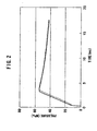
- the required gas pressure can be achieved in a shorter time, shortening the time it takes to activate the vehicle safety system to protect the occupants in the event of a crash.
- the broken line shows gas pressure plotted against time in the case of a conventional gas generation apparatus.
- Figure 3 is a graph of the results of a test to check the moistureproof properties with respect to the gas generating material 19.
- the gas generation apparatus was exposed for periods of thirty minutes at each of the temperatures 0°C, 20°C, 40°C and 105°C; at 20°C and 40°C a humidity of 90 to 98% was maintained.
- the graph was obtained by running the tests a prescribed number of cycles and measuring the coefficient of moisture absorption of each gas generating material 19.
- the solid line denotes the gas generation apparatus of this invention and the broken line a prior art gas generation apparatus. From the graph, it can be seen that the gas generation apparatus of this invention exhibited much better moistureproof properties than the prior art apparatus using vulcanized seal material P. These results show that even under high humidity, the gas generating material 19 will burn more reliably than that of the prior art.
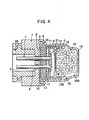
- FIG 4 is a cross-sectional diagram of a second embodiment of the electric ignition type gas generation apparatus of the invention.
- this gas generation apparatus shown here is for use with a vehicle safety device such as a seatbelt or airbag or the like.
- the difference between the apparatuses of the first and second embodiments lies in the arrangement of the ignition charge 18 and gas generating material 19 in the outer casing 16.
- a cover 21 is provided on the upper surface of the printed circuit board 8 on which the priming charge 14 is disposed.
- the ignition charge 18 is disposed within the cover 21, while the outer casing 16 contains only the gas generating material 19.
- the cover 21 is cylindrically formed of resin or the like, and has a thin cover portion 22.
- the cover 21 is affixed to the base 1 by being caulked by the peripheral wall 4 used for attaching the ignition section.
- the configuration is the same as that of the first embodiment and the same reference symbols are used, so further explanation of the details thereof are omitted.
- the gas generation apparatus when in a crash the impact is transmitted as an electric signal to the electrode pins 7, the resistance (not shown) between the electrode pins 7 heats up, which ignites the priming charge 14 to thereby set off the ignition charge 18.
- the ignition of the ignition charge 18 ruptures the cover portion 22 of the cover 21, allowing the flame of the ignition to reach the gas generating material 19, initiating combustion of the gas generating material 19.
- the gas thus generated ruptures the bottom of the outer casing 16 and is thereby instantaneously released to the outside, instantaneously activating the seatbelt rapid retraction means, airbag or other such vehicle safety system.
- the ignition charge 18 is disposed on the inside of the cover 21, the flame produced by the ignition of the ignition charge 18 is larger than that produced in the case of the gas generation apparatus of the first embodiment, which makes it possible to ignite the gas generating material 19 more efficiently and instantaneously. Moreover, as the gas generating material 19 does not directly contact the priming charge 14, even if the gas generation apparatus is subjected to vibration, the gas generating material 19 cannot impact against the priming charge 14.
- the addition of the cover 21 means that the apparatus of the second embodiment has a larger number of parts than the apparatus of the first embodiment, like the first embodiment, it still has far fewer parts than a prior art apparatus and can therefore be manufactured at less cost. Similarly, while the addition of the cover 21 means that the apparatus is that much larger than the apparatus of the first embodiment, it is still smaller than a prior art apparatus. Assuming the same functionality, for example, the length of the apparatus of this invention is 80% that of a prior art apparatus and has only around 80% as many parts. The apparatus of the second embodiment also exhibits the same moistureproofing and pressure resistance properties as the first embodiment.
- the apparatus can also be applied to a safety device such as an airbag device for protecting people from the shock of falls, rolling and other such crash impacts.
- a varistor is used to improve resistance to static electricity
- the invention is not limited to the use of a varistor.
- conductive resin or the like may be used for the purpose where the use of such material does not pose a problem.
- conductive resin containing lead wires may be used for the hermetic material.
- the apparatus comprises an ignition section formed on an apparatus base, and a gas generating section provided on the base with the gas generating section covering the ignition section.
- This enables the number of parts, the manufacturing cost and the size of the apparatus to be reduced. Therefore, when applied to a rapid retraction device of a seatbelt or an airbag or other such vehicle safety device, or to an airbag device used to protect people from the shock of falls, rolling and other such crash impacts, it enables the cost and size of such devices to be reduced.
- using a varistor to provide a connection between the electric input portions of the ignition section and using unvulcanized rubber as a seal material for the gas generating section improves the reliability of the apparatus by improving the resistance to static electricity and the moistureproof properties.
Landscapes
- Engineering & Computer Science (AREA)
- General Engineering & Computer Science (AREA)
- Physics & Mathematics (AREA)
- Fluid Mechanics (AREA)
- Mechanical Engineering (AREA)
- Computer Hardware Design (AREA)
- Microelectronics & Electronic Packaging (AREA)
- Air Bags (AREA)
- Feeding, Discharge, Calcimining, Fusing, And Gas-Generation Devices (AREA)
- Automotive Seat Belt Assembly (AREA)
- Gas-Insulated Switchgears (AREA)
Claims (3)
- Appareil générateur de gaz du type à allumage électrique comprenant une base d'appareil (1) dotée d'une paroi périphérique (4) pour fixer une section d'allumage (100) qui comprend une charge d'amorçage (14), et une paire de broches d'électrode (7) pour allumer ladite section d'allumage (100) au moyen d'un signal électrique, et une section de génération de gaz (200) couvrant la section d'allumage (100), du gaz étant généré dans ladite section de génération de gaz (200) par l'allumage de la section d'allumage (100), la section d'allumage (100) comprenant un matériau de joint (9) pour sceller la section de génération de gaz (200) et une carte de circuit imprimé (8), ladite paire de broches d'électrode (7) étant connectée à la carte de circuit imprimé (8), caractérisé- en ce que la section d'allumage (100) comprend en outre un matériau hermétique (10), ladite paire de broches d'électrode (7) s'étendant à travers la base (1) de l'appareil, le matériau de joint (9) et le matériau hermétique (10),- en ce que ledit matériau de joint (9) est un caoutchouc non vulcanisé,- et en ce que ladite base (1) de l'appareil est en aluminium.
- Appareil selon la revendication 1, caractérisé en ce que lesdites broches d'électrode (7) sont connectées l'une à l'autre par une varistance (11).
- Appareil selon l'une quelconque des revendications précédentes, caractérisé en ce que la section d'allumage (100) comprend une pâte (15) pour enduire la charge d'amorçage (14).
Applications Claiming Priority (2)
| Application Number | Priority Date | Filing Date | Title |
|---|---|---|---|
| JP10209299 | 1999-04-09 | ||
| JP11102092A JP2000292100A (ja) | 1999-04-09 | 1999-04-09 | 電気点火式ガス発生装置 |
Publications (3)
| Publication Number | Publication Date |
|---|---|
| EP1043201A2 EP1043201A2 (fr) | 2000-10-11 |
| EP1043201A3 EP1043201A3 (fr) | 2002-11-27 |
| EP1043201B1 true EP1043201B1 (fr) | 2007-02-21 |
Family
ID=14318145
Family Applications (1)
| Application Number | Title | Priority Date | Filing Date |
|---|---|---|---|
| EP00302989A Expired - Lifetime EP1043201B1 (fr) | 1999-04-09 | 2000-04-10 | Appareil générateur de gaz à allumage électrique |
Country Status (6)
| Country | Link |
|---|---|
| US (1) | US6301892B1 (fr) |
| EP (1) | EP1043201B1 (fr) |
| JP (1) | JP2000292100A (fr) |
| AT (1) | ATE354503T1 (fr) |
| DE (1) | DE60033462T2 (fr) |
| ES (1) | ES2280175T3 (fr) |
Families Citing this family (20)
| Publication number | Priority date | Publication date | Assignee | Title |
|---|---|---|---|---|
| DE20020102U1 (de) | 2000-11-27 | 2001-04-05 | TRW Airbag Systems GmbH & Co. KG, 84544 Aschau | Pyrotechnische, gaserzeugende Vorrichtung |
| DE10116785B4 (de) * | 2001-04-04 | 2006-02-23 | Nico-Pyrotechnik Hanns-Jürgen Diederichs GmbH & Co KG | Zündeinrichtung für eine Insassenschutzvorrichtung eines Kraftfahrzeuges |
| WO2003008896A1 (fr) * | 2001-07-13 | 2003-01-30 | Hirtenberger Automotive Safety Gmbh | Amorce pyrotechnique |
| ATE372499T1 (de) * | 2002-02-09 | 2007-09-15 | Delphi Tech Inc | Pyrotechnische zündkette mit einem anzündträger aus kunststoff mit integrierter metalleinlage |
| JP3906910B2 (ja) | 2002-03-29 | 2007-04-18 | トヨタ自動車株式会社 | イニシエータ |
| AU2003252223A1 (en) | 2002-07-19 | 2004-02-23 | Nippon Kayaku Kabushiki Kaisha | Gas generator |
| JP4206009B2 (ja) * | 2002-09-02 | 2009-01-07 | ダイセル化学工業株式会社 | インフレータ用点火器及びその製造方法 |
| US6976430B2 (en) | 2002-09-02 | 2005-12-20 | Daicel Chemical Industries, Ltd. | Igniter for inflator and method of manufacturing thereof |
| JP2005001601A (ja) * | 2003-06-13 | 2005-01-06 | Takata Corp | ガス発生器 |
| US20060208474A1 (en) * | 2003-12-24 | 2006-09-21 | Nippon Kayaku Kabushiki Kaisha | Gas producer |
| FR2868833B1 (fr) * | 2004-04-07 | 2006-06-16 | Ncs Pyrotechnie & Tech | Initiateur electro-pyrotechnique a fil et son procede de fabrication |
| US20070163457A1 (en) * | 2004-04-16 | 2007-07-19 | Nippon Kayaku Kabushiki Kaisha | Igniter and gas generator having the same |
| DE102005004920B3 (de) * | 2005-02-02 | 2006-08-17 | Amphenol-Tuchel Electronics Gmbh | Kontaktsicherung für Steckverbinder mit einer Kurzschlussbrücke mit integriertem Schaltelement |
| JP2008049941A (ja) * | 2006-08-28 | 2008-03-06 | Daicel Chem Ind Ltd | ガス発生器 |
| JP4705550B2 (ja) * | 2006-10-26 | 2011-06-22 | 日本化薬株式会社 | スクイブならびにエアバッグ用ガス発生装置およびシートベルトプリテンショナー用ガス発生装置 |
| EP2409880B1 (fr) * | 2009-03-19 | 2015-08-19 | Autoliv Development AB | Dispositif de commande de dispositif de retenue de passager |
| US8056477B2 (en) * | 2009-06-10 | 2011-11-15 | Autoliv Asp, Inc. | Protection system for use with airbag inflators and initiators |
| JP5450306B2 (ja) * | 2010-07-29 | 2014-03-26 | 株式会社ダイセル | ガス発生器 |
| JP6655897B2 (ja) * | 2015-07-03 | 2020-03-04 | 株式会社ダイセル | 点火手段とそれを使用したガス発生器 |
| JP7271462B2 (ja) * | 2020-03-02 | 2023-05-11 | 日本化薬株式会社 | ガス発生器 |
Family Cites Families (10)
| Publication number | Priority date | Publication date | Assignee | Title |
|---|---|---|---|---|
| US4045959A (en) * | 1975-03-17 | 1977-09-06 | Honeywell Inc. | Expanded ring bellows |
| US4054032A (en) * | 1976-09-03 | 1977-10-18 | Networks Electronic Corporation | Explosive actuated pin puller |
| FR2557689B1 (fr) * | 1983-12-28 | 1987-06-12 | Poudres & Explosifs Ste Nale | Initiateur pyrotechnique utilisant une prise coaxiale |
| DE4002088C1 (fr) * | 1990-01-25 | 1990-08-23 | Bayern-Chemie Gesellschaft Fuer Flugchemische Antriebe Mbh, 8261 Aschau, De | |
| JPH07149202A (ja) * | 1993-08-19 | 1995-06-13 | Nippon Oil & Fats Co Ltd | 機械発火式ガス発生器 |
| US5728964A (en) * | 1993-10-20 | 1998-03-17 | Quantic Industries, Inc. | Electrical initiator |
| DE4435319A1 (de) * | 1994-10-01 | 1996-04-04 | Temic Bayern Chem Airbag Gmbh | Anzündeinheit für einen Gasgenerator eines passiven Rückhaltesystems |
| US5798497A (en) * | 1995-02-02 | 1998-08-25 | Battelle Memorial Institute | Tunable, self-powered integrated arc plasma-melter vitrification system for waste treatment and resource recovery |
| US5672841A (en) * | 1995-12-15 | 1997-09-30 | Morton International, Inc. | Inflator initiator with zener diode electrostatic discharge protection |
| US5932832A (en) * | 1996-04-15 | 1999-08-03 | Autoliv Asp, Inc. | High pressure resistant initiator with integral metal oxide varistor for electro-static discharge protection |
-
1999
- 1999-04-09 JP JP11102092A patent/JP2000292100A/ja active Pending
-
2000
- 2000-04-10 ES ES00302989T patent/ES2280175T3/es not_active Expired - Lifetime
- 2000-04-10 AT AT00302989T patent/ATE354503T1/de not_active IP Right Cessation
- 2000-04-10 EP EP00302989A patent/EP1043201B1/fr not_active Expired - Lifetime
- 2000-04-10 DE DE60033462T patent/DE60033462T2/de not_active Expired - Lifetime
- 2000-04-10 US US09/545,927 patent/US6301892B1/en not_active Expired - Lifetime
Also Published As
| Publication number | Publication date |
|---|---|
| ES2280175T3 (es) | 2007-09-16 |
| JP2000292100A (ja) | 2000-10-20 |
| DE60033462T2 (de) | 2007-11-08 |
| US6301892B1 (en) | 2001-10-16 |
| EP1043201A3 (fr) | 2002-11-27 |
| DE60033462D1 (de) | 2007-04-05 |
| ATE354503T1 (de) | 2007-03-15 |
| EP1043201A2 (fr) | 2000-10-11 |
Similar Documents
| Publication | Publication Date | Title |
|---|---|---|
| US6301892B1 (en) | Electric ignition type gas generation apparatus | |
| US6009809A (en) | Bridgewire initiator | |
| EP1383664B1 (fr) | Generateur de gaz | |
| JP3463263B2 (ja) | 点火装置 | |
| JP2909007B2 (ja) | 圧力センサを備えたエアバッグ膨張器 | |
| JP4864234B2 (ja) | エアバッグ用ガス発生器 | |
| US6796245B2 (en) | Unitary header/base/shorting bar holder for a micro gas generator, and micro gas generator using it | |
| JPH06341793A (ja) | イグナイター | |
| CN1323875C (zh) | 气体发生器 | |
| EP1424249A1 (fr) | Generateur de gaz | |
| US5939660A (en) | Inflator for an inflatable vehicle occupant protection device | |
| CA2128258A1 (fr) | Allumage direct par laser de produits inflammables lineaires | |
| WO2008050860A1 (fr) | Amorce, dispositif de génération de gaz pour coussin de sécurité gonflable et dispositif de génération de gaz pour prétendeur de ceinture de sécurité | |
| EP1035400B1 (fr) | Prétensionneur avec connection de mise à la terre du boitier d'allumeur | |
| CZ20033416A3 (en) | Gas generator | |
| JP2003205823A (ja) | ガス発生器 | |
| US9248802B2 (en) | Surface mount initiators | |
| GB2315118A (en) | Electro-explosvie device | |
| WO2022239790A1 (fr) | Ensemble allumeur et dispositif de génération de gaz | |
| JP2536357Y2 (ja) | エアバッグ展開用ガス発生装置におけるイグナイターの点火部構造 | |
| JP2536356Y2 (ja) | エアバッグ展開用ガス発生装置のイグナイター | |
| WO2000073729A1 (fr) | Allumeur, tete d'allumeur et bouchon d'allumeur | |
| KR20010002053A (ko) | 장약 조성물과 그것을 포함한 점화기 | |
| JPWO2007078000A1 (ja) | 点火装置ならびにエアバッグ用ガス発生装置およびシートベルトプリテンショナー用ガス発生装置 | |
| JP2512473Y2 (ja) | イグナイタ― |
Legal Events
| Date | Code | Title | Description |
|---|---|---|---|
| PUAI | Public reference made under article 153(3) epc to a published international application that has entered the european phase |
Free format text: ORIGINAL CODE: 0009012 |
|
| AK | Designated contracting states |
Kind code of ref document: A2 Designated state(s): AT BE CH CY DE DK ES FI FR GB GR IE IT LI LU MC NL PT SE |
|
| AX | Request for extension of the european patent |
Free format text: AL;LT;LV;MK;RO;SI |
|
| PUAL | Search report despatched |
Free format text: ORIGINAL CODE: 0009013 |
|
| AK | Designated contracting states |
Kind code of ref document: A3 Designated state(s): AT BE CH CY DE DK ES FI FR GB GR IE IT LI LU MC NL PT SE |
|
| AX | Request for extension of the european patent |
Free format text: AL;LT;LV;MK;RO;SI |
|
| RIC1 | Information provided on ipc code assigned before grant |
Free format text: 7B 60R 21/26 A, 7F 42B 3/12 B, 7F 42B 3/26 B |
|
| 17P | Request for examination filed |
Effective date: 20030520 |
|
| AKX | Designation fees paid |
Designated state(s): AT BE CH CY DE DK ES FI FR GB GR IE IT LI LU MC NL PT SE |
|
| 17Q | First examination report despatched |
Effective date: 20031015 |
|
| GRAP | Despatch of communication of intention to grant a patent |
Free format text: ORIGINAL CODE: EPIDOSNIGR1 |
|
| GRAS | Grant fee paid |
Free format text: ORIGINAL CODE: EPIDOSNIGR3 |
|
| GRAA | (expected) grant |
Free format text: ORIGINAL CODE: 0009210 |
|
| AK | Designated contracting states |
Kind code of ref document: B1 Designated state(s): AT BE CH CY DE DK ES FI FR GB GR IE IT LI LU MC NL PT SE |
|
| PG25 | Lapsed in a contracting state [announced via postgrant information from national office to epo] |
Ref country code: NL Free format text: LAPSE BECAUSE OF FAILURE TO SUBMIT A TRANSLATION OF THE DESCRIPTION OR TO PAY THE FEE WITHIN THE PRESCRIBED TIME-LIMIT Effective date: 20070221 Ref country code: BE Free format text: LAPSE BECAUSE OF FAILURE TO SUBMIT A TRANSLATION OF THE DESCRIPTION OR TO PAY THE FEE WITHIN THE PRESCRIBED TIME-LIMIT Effective date: 20070221 Ref country code: CH Free format text: LAPSE BECAUSE OF FAILURE TO SUBMIT A TRANSLATION OF THE DESCRIPTION OR TO PAY THE FEE WITHIN THE PRESCRIBED TIME-LIMIT Effective date: 20070221 Ref country code: DK Free format text: LAPSE BECAUSE OF FAILURE TO SUBMIT A TRANSLATION OF THE DESCRIPTION OR TO PAY THE FEE WITHIN THE PRESCRIBED TIME-LIMIT Effective date: 20070221 Ref country code: FI Free format text: LAPSE BECAUSE OF FAILURE TO SUBMIT A TRANSLATION OF THE DESCRIPTION OR TO PAY THE FEE WITHIN THE PRESCRIBED TIME-LIMIT Effective date: 20070221 Ref country code: AT Free format text: LAPSE BECAUSE OF FAILURE TO SUBMIT A TRANSLATION OF THE DESCRIPTION OR TO PAY THE FEE WITHIN THE PRESCRIBED TIME-LIMIT Effective date: 20070221 Ref country code: LI Free format text: LAPSE BECAUSE OF FAILURE TO SUBMIT A TRANSLATION OF THE DESCRIPTION OR TO PAY THE FEE WITHIN THE PRESCRIBED TIME-LIMIT Effective date: 20070221 |
|
| REG | Reference to a national code |
Ref country code: GB Ref legal event code: FG4D |
|
| REG | Reference to a national code |
Ref country code: CH Ref legal event code: EP |
|
| REF | Corresponds to: |
Ref document number: 60033462 Country of ref document: DE Date of ref document: 20070405 Kind code of ref document: P |
|
| REG | Reference to a national code |
Ref country code: IE Ref legal event code: FG4D |
|
| PG25 | Lapsed in a contracting state [announced via postgrant information from national office to epo] |
Ref country code: SE Free format text: LAPSE BECAUSE OF FAILURE TO SUBMIT A TRANSLATION OF THE DESCRIPTION OR TO PAY THE FEE WITHIN THE PRESCRIBED TIME-LIMIT Effective date: 20070521 |
|
| ET | Fr: translation filed | ||
| PG25 | Lapsed in a contracting state [announced via postgrant information from national office to epo] |
Ref country code: PT Free format text: LAPSE BECAUSE OF FAILURE TO SUBMIT A TRANSLATION OF THE DESCRIPTION OR TO PAY THE FEE WITHIN THE PRESCRIBED TIME-LIMIT Effective date: 20070723 |
|
| NLV1 | Nl: lapsed or annulled due to failure to fulfill the requirements of art. 29p and 29m of the patents act | ||
| REG | Reference to a national code |
Ref country code: CH Ref legal event code: PL |
|
| REG | Reference to a national code |
Ref country code: ES Ref legal event code: FG2A Ref document number: 2280175 Country of ref document: ES Kind code of ref document: T3 |
|
| PLBE | No opposition filed within time limit |
Free format text: ORIGINAL CODE: 0009261 |
|
| STAA | Information on the status of an ep patent application or granted ep patent |
Free format text: STATUS: NO OPPOSITION FILED WITHIN TIME LIMIT |
|
| 26N | No opposition filed |
Effective date: 20071122 |
|
| PG25 | Lapsed in a contracting state [announced via postgrant information from national office to epo] |
Ref country code: IT Free format text: LAPSE BECAUSE OF FAILURE TO SUBMIT A TRANSLATION OF THE DESCRIPTION OR TO PAY THE FEE WITHIN THE PRESCRIBED TIME-LIMIT Effective date: 20070221 Ref country code: GR Free format text: LAPSE BECAUSE OF FAILURE TO SUBMIT A TRANSLATION OF THE DESCRIPTION OR TO PAY THE FEE WITHIN THE PRESCRIBED TIME-LIMIT Effective date: 20070522 |
|
| PG25 | Lapsed in a contracting state [announced via postgrant information from national office to epo] |
Ref country code: IE Free format text: LAPSE BECAUSE OF NON-PAYMENT OF DUE FEES Effective date: 20070410 |
|
| PG25 | Lapsed in a contracting state [announced via postgrant information from national office to epo] |
Ref country code: MC Free format text: LAPSE BECAUSE OF NON-PAYMENT OF DUE FEES Effective date: 20070430 |
|
| PG25 | Lapsed in a contracting state [announced via postgrant information from national office to epo] |
Ref country code: CY Free format text: LAPSE BECAUSE OF FAILURE TO SUBMIT A TRANSLATION OF THE DESCRIPTION OR TO PAY THE FEE WITHIN THE PRESCRIBED TIME-LIMIT Effective date: 20070221 |
|
| PG25 | Lapsed in a contracting state [announced via postgrant information from national office to epo] |
Ref country code: LU Free format text: LAPSE BECAUSE OF NON-PAYMENT OF DUE FEES Effective date: 20070410 |
|
| PGFP | Annual fee paid to national office [announced via postgrant information from national office to epo] |
Ref country code: FR Payment date: 20100506 Year of fee payment: 11 Ref country code: ES Payment date: 20100426 Year of fee payment: 11 |
|
| PGFP | Annual fee paid to national office [announced via postgrant information from national office to epo] |
Ref country code: DE Payment date: 20100423 Year of fee payment: 11 |
|
| PGFP | Annual fee paid to national office [announced via postgrant information from national office to epo] |
Ref country code: GB Payment date: 20100420 Year of fee payment: 11 |
|
| REG | Reference to a national code |
Ref country code: DE Ref legal event code: R119 Ref document number: 60033462 Country of ref document: DE |
|
| REG | Reference to a national code |
Ref country code: DE Ref legal event code: R119 Ref document number: 60033462 Country of ref document: DE |
|
| GBPC | Gb: european patent ceased through non-payment of renewal fee |
Effective date: 20110410 |
|
| REG | Reference to a national code |
Ref country code: FR Ref legal event code: ST Effective date: 20111230 |
|
| PG25 | Lapsed in a contracting state [announced via postgrant information from national office to epo] |
Ref country code: FR Free format text: LAPSE BECAUSE OF NON-PAYMENT OF DUE FEES Effective date: 20110502 |
|
| PG25 | Lapsed in a contracting state [announced via postgrant information from national office to epo] |
Ref country code: GB Free format text: LAPSE BECAUSE OF NON-PAYMENT OF DUE FEES Effective date: 20110410 |
|
| PG25 | Lapsed in a contracting state [announced via postgrant information from national office to epo] |
Ref country code: DE Free format text: LAPSE BECAUSE OF NON-PAYMENT OF DUE FEES Effective date: 20111031 |
|
| REG | Reference to a national code |
Ref country code: ES Ref legal event code: FD2A Effective date: 20131029 |
|
| PG25 | Lapsed in a contracting state [announced via postgrant information from national office to epo] |
Ref country code: ES Free format text: LAPSE BECAUSE OF NON-PAYMENT OF DUE FEES Effective date: 20110411 |