EP1044591B1 - Système de gestion de la fonction pour véhicules - Google Patents
Système de gestion de la fonction pour véhicules Download PDFInfo
- Publication number
- EP1044591B1 EP1044591B1 EP00107566A EP00107566A EP1044591B1 EP 1044591 B1 EP1044591 B1 EP 1044591B1 EP 00107566 A EP00107566 A EP 00107566A EP 00107566 A EP00107566 A EP 00107566A EP 1044591 B1 EP1044591 B1 EP 1044591B1
- Authority
- EP
- European Patent Office
- Prior art keywords
- sequence
- control unit
- management system
- switch
- function
- Prior art date
- Legal status (The legal status is an assumption and is not a legal conclusion. Google has not performed a legal analysis and makes no representation as to the accuracy of the status listed.)
- Expired - Lifetime
Links
- 230000006870 function Effects 0.000 claims description 58
- 230000004913 activation Effects 0.000 claims 5
- 206010000210 abortion Diseases 0.000 claims 1
- 230000005540 biological transmission Effects 0.000 description 13
- 230000000994 depressogenic effect Effects 0.000 description 3
- 238000010586 diagram Methods 0.000 description 3
- 230000007935 neutral effect Effects 0.000 description 3
- 238000004891 communication Methods 0.000 description 2
- 230000000694 effects Effects 0.000 description 2
- 239000012530 fluid Substances 0.000 description 2
- 238000000034 method Methods 0.000 description 2
- 238000012986 modification Methods 0.000 description 2
- 230000004048 modification Effects 0.000 description 2
- 230000004044 response Effects 0.000 description 2
- 230000005355 Hall effect Effects 0.000 description 1
- 241001236644 Lavinia Species 0.000 description 1
- 241000947772 Strawberry crinkle virus Species 0.000 description 1
- 238000007792 addition Methods 0.000 description 1
- 238000003967 crop rotation Methods 0.000 description 1
- 230000001419 dependent effect Effects 0.000 description 1
- 230000000881 depressing effect Effects 0.000 description 1
- 238000011161 development Methods 0.000 description 1
- 230000018109 developmental process Effects 0.000 description 1
- 238000003306 harvesting Methods 0.000 description 1
- 230000010354 integration Effects 0.000 description 1
- 230000008569 process Effects 0.000 description 1
- 239000002689 soil Substances 0.000 description 1
- 230000001052 transient effect Effects 0.000 description 1
- 230000007704 transition Effects 0.000 description 1
Images


Classifications
-
- E—FIXED CONSTRUCTIONS
- E02—HYDRAULIC ENGINEERING; FOUNDATIONS; SOIL SHIFTING
- E02F—DREDGING; SOIL-SHIFTING
- E02F9/00—Component parts of dredgers or soil-shifting machines, not restricted to one of the kinds covered by groups E02F3/00 - E02F7/00
- E02F9/20—Drives; Control devices
-
- A—HUMAN NECESSITIES
- A01—AGRICULTURE; FORESTRY; ANIMAL HUSBANDRY; HUNTING; TRAPPING; FISHING
- A01B—SOIL WORKING IN AGRICULTURE OR FORESTRY; PARTS, DETAILS, OR ACCESSORIES OF AGRICULTURAL MACHINES OR IMPLEMENTS, IN GENERAL
- A01B63/00—Lifting or adjusting devices or arrangements for agricultural machines or implements
- A01B63/02—Lifting or adjusting devices or arrangements for agricultural machines or implements for implements mounted on tractors
- A01B63/10—Lifting or adjusting devices or arrangements for agricultural machines or implements for implements mounted on tractors operated by hydraulic or pneumatic means
- A01B63/111—Lifting or adjusting devices or arrangements for agricultural machines or implements for implements mounted on tractors operated by hydraulic or pneumatic means regulating working depth of implements
- A01B63/1117—Lifting or adjusting devices or arrangements for agricultural machines or implements for implements mounted on tractors operated by hydraulic or pneumatic means regulating working depth of implements using a hitch position sensor
-
- E—FIXED CONSTRUCTIONS
- E02—HYDRAULIC ENGINEERING; FOUNDATIONS; SOIL SHIFTING
- E02F—DREDGING; SOIL-SHIFTING
- E02F9/00—Component parts of dredgers or soil-shifting machines, not restricted to one of the kinds covered by groups E02F3/00 - E02F7/00
- E02F9/26—Indicating devices
-
- G—PHYSICS
- G05—CONTROLLING; REGULATING
- G05B—CONTROL OR REGULATING SYSTEMS IN GENERAL; FUNCTIONAL ELEMENTS OF SUCH SYSTEMS; MONITORING OR TESTING ARRANGEMENTS FOR SUCH SYSTEMS OR ELEMENTS
- G05B2219/00—Program-control systems
- G05B2219/20—Pc systems
- G05B2219/23—Pc programming
- G05B2219/23423—Record playback
-
- G—PHYSICS
- G05—CONTROLLING; REGULATING
- G05B—CONTROL OR REGULATING SYSTEMS IN GENERAL; FUNCTIONAL ELEMENTS OF SUCH SYSTEMS; MONITORING OR TESTING ARRANGEMENTS FOR SUCH SYSTEMS OR ELEMENTS
- G05B2219/00—Program-control systems
- G05B2219/20—Pc systems
- G05B2219/26—Pc applications
- G05B2219/2663—Tractor
Definitions
- the invention relates to a function management system for vehicles, which has at least one function that can perform certain operations when driving the vehicle depending on settings on at least one, the function associated control element using a control unit.
- Such a function management system is for example from the US 5,050,771 known.
- the object underlying the invention is seen to provide a function management system of the type mentioned, by which the aforementioned problems are overcome.
- the function management should simplify the operation of a work vehicle such as an agricultural tractor.
- a tractor includes various functional systems, also called functions, such as a powershift transmission, a hitch with a hitch control, a PTO, several auxiliary control valves, etc. controlled by a control unit in response to detected parameters and depending on the adjustment of controls such as switches and levers operating an operator, to be controlled.
- the control unit includes a learning mode that is operable while the vehicle is moving. During the execution of the learning mode, the operator performs a sequence of manipulations on the controllers, and the controller stores information associated with the sequences along with information related to the distances the tractor between two Completed operations.
- the control unit also has a run or repeat mode in which it automatically executes the stored work sequence so that the work sequence is executed at the same distance intervals at which it was learned, regardless of the vehicle speed.
- the function management according to the invention makes it possible to considerably reduce the operating requirements for a work vehicle, such as an agricultural tractor, imposed on an operator.
- the functional management system according to the invention is able to learn and store various operational sequences of functional operations and to execute and repeat such learned operations on command. The operations are learned as a function of driving distances of the vehicle so that the working sequences are automatically repeated at the same intermediate distance ratios as learned.
- the vehicle underlying FIG. 1 is, for example, a commercially available John Deere Series 8000 Series Tractor and includes a prime mover 10 which drives an output shaft which in turn drives a powershift transmission (PST) 12 which in turn drives an output drive shaft connected to the Drive wheels 17 of the vehicle is in communication.
- the power shift transmission 12 includes a transmission 18 which is actuated by a set of pressure actuated elements or clutches 20 actuated by a set of associated solenoid operated control valves 22.
- the power shift transmission 12 may be one used in the aforementioned John Deere series tractor. However, it can also be any electronically controlled transmission with similar controls.
- the valves 22 may be electro-hydraulically actuated valves, as also used in the John Deere series tractor.
- the prime mover 10 additionally drives the PTO drive, not shown, for a conventional power take off (PTO) and a hydraulic pump which delivers pressurized hydraulic fluid to auxiliary control valves (not shown), also known from the John Deere series tractor.
- a tractor can, for example, a switchable differential lock and Include a switchable mechanical front wheel drive.
- electro-hydraulic depth control cylinder can be located on the not shown, pulled by the tractor attachment.
- An attachment device such as a conventional 3-point hitch, includes tension members (lower links) 32 which are connected via lift rods 36 to lift arms 34.
- the lifting arms 34 are connected to a lifting shaft 28, that a simultaneous and equal movement is ensured. They are raised or lowered by two lifting cylinders 38 connected in parallel.
- the illustrated tractor cutout and hitch 30 are shown by way of example only, it will be apparent to those skilled in the art that the invention can be applied to tractors or hitches of other configurations.
- various types of non-illustrated soil working implements such as a mouldboard plow or a chisel plow, may be attached to the hitch 30 in a conventional manner.
- the power shift transmission 12, the hitch 30, a PTO, not shown, additional control valves, a differential lock, not shown front wheel drive and not shown electro-hydraulic depth control cylinder are examples of different types of functions or actuators, during the tractor operation, for example on Beginning or end of a crop row in the desired sequence (sequence) to be pressed.
- the hydraulic fluid communication to and from the cylinders 38 is controlled by two electro-hydraulic flow control solenoid valves 40a and 40b, which in turn are controlled by drivers 42a and 42b which receive electrical control signals generated by the vehicle control unit (VCU) 44.
- the VCU 44 is preferably a microprocessor-based electronic control unit as it is used on John Deere Series 8000 series tractors. Also, the flow control valves 40a and 40b and the drivers 42a and 42b may be components already used in the John Deere series tractor.
- the VCU 44 preferably also controls a differential lock, not shown, a not shown mechanical front wheel drive, a PTO, not shown, not shown auxiliary control valves, as they are all known for example from the John Deere series tractor.
- the VCU 44 receives signals from a spring-centered rocker switch 46, which has three positions and which serves to raise and lower (H / S) the implement 30, a vehicle monitor / display unit 48, and a gearshift unit 50, all of them from the John Deere series tugs are known.
- the VCU 44 also receives signals from an engine speed sensor 52, preferably a magnetic pickup, and an axle speed sensor 54, preferably a Hall effect sensor, that provides an axle speed signal.
- Components 52 and 54 are preferably similar to the corresponding components of the John Deere series tractor. However, corresponding components which are otherwise commercially available are also suitable.
- the VCU 44 also receives signals from a self-centering sequence switch 56 that is switchable between a first and a second sequence and that is configured as a commercially available flip-flop switchable between three positions (1st sequence, 2nd sequence and neutral) and in conjunction with the present one Invention is used.
- the VCU 44 includes an input and output circuit, a programmable microprocessor, and a memory, not shown.
- the VCU 44 also receives signals from a clutch switch 57 which operatively communicates with the clutch pedal 58.
- the monitor / display unit 48 shown in Figure 2 is similar to the monitor / display unit used in John Deere Series 8000 series tractors, but with some additions and / or changes as will be described.
- the left third of the monitor / display unit 48 includes a plurality of warning and status lights 60 associated with various vehicle functions, but not directly related to the present invention.
- the upper, middle portion of the unit 48 includes a graphics and number display 62.
- the lower, middle portion of the unit 48 includes a plurality of touch pad switches 64 (which are also not within the scope of the present invention) that allow adjustment. which parameters should be indicated by the numeric part of the display.
- the upper part and lower part of the right third of the monitor / display unit 48 may include non-illustrated touch surface switches not belonging to the present invention.
- the unit 48 also includes a speaker, not shown, which emits acoustic signals in response to certain conditions and operations.
- the middle part of the right third of the monitor / display unit 48 includes an on / off switch 66 and a learn / store switch 68, both of which may be a touch pad switch and used in conjunction with the present invention functional management system according to the invention can be used.
- the lower right portion of the display 62 includes a HMI system IMS (Implement Management System) indicator 70 and a display element 72 for indicating the operative sequence (1 or 2).
- the display elements 70, 72 light up depending on the functional status according to the present invention, as will be described.
- the VCU 44 is programmed accordingly.
- the programmed VCU 44 derives the required distance information using known integration techniques from the speed sensor 54.
- the programmed VCU 44 cooperates with the elements shown in FIGS. 1 and 2 and thereby implements the function management system according to the invention.
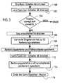
- the learn / store mode operates as follows: In step 100, the system is first turned on by pressing the on / off switch 66 and the IMS indicator 70 turns on. By depressing the learn / memory switch 68, step 102 activates the learn / memory mode, the IMS indicator 70 begins to flash, and an audible alarm sounds every two seconds.
- step 104 the learn / save mode continues as long as a forward gear is adjusted on the transmission 18 and the tractor is moving faster than a minimum speed, for example, 0.5 km / h.
- the function management system exits the learning / memory mode and cancels it. The previously determined sequences are deleted.
- step 106 the operator temporarily actuates the sequence switch 56 to set the sequence 1 or sequence 2.
- the associated sequence number of the sequence display element 72 starts to flash.
- step 108 the operator may manually execute a sequence (sequence) of functional operator commands that may be limited to a maximum number (e.g., 12).
- the operation commands are, for example, shifting the transmission 18 by operating the shift lever 50, or raising and / or lowering the attachment 30 by operating the raise / lower rocker switch 46.
- the VCU 44 records in step 110 (in FIG temporary memory) all manually executed operations together with the associated driving distances, the tractor between the various manually executed operations.
- step 112 the learn / memory switch 68 is pressed again, and through step 114, the VCU 44 stores in a permanent memory the operating sequence and the associated driving distances, as well as the sequence number 1 or 2, which depends on which position the switch 56 before (step 106) was pressed.
- the learn / save mode then ends with step 116, the sequence indicator 72 stops flashing and only the IMS indicator 70 remains illuminated.
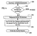
- Step 200 the on / off switch 66 is depressed to turn on the function management system.
- the IMS indicator lights up.
- Step 202 allows the execution mode to proceed when the tractor gearbox 18 is in a forward gear and the tractor is moving faster than a minimum speed.
- the operator temporarily depresses the sequence switch 56 to the "1" position or the "2" position to select which of the stored sequences will be played should.
- the "1" or "2" of the sequence display element 72 lights up and remains on for at least 3 seconds, even if the sequence to be executed takes less than 3 seconds. Then, the VCU 44 automatically executes the selected one in step 206 Sequence of stored operating commands. For example, the transmission 18 is automatically switched without the operator operating the gearshift lever 50, or the hitch 30 is automatically raised and / or lowered without the operator operating the lift / lower rocker switch 46. The stored operator commands are each executed at the same relative distances as learned, regardless of whether the tractor is traveling at the same, lower, or higher speed. When the sequence is completed, the "1" or "2" of the sequence display element 72 goes out. The execution mode then ends with step 208.
- the operator can temporarily toggle the sequence switch 56 to its "1" position for the first sequence for example, automatically execute at the end of each harvest series.
- the operator may temporarily flip the sequence switch 56 to its "2" position to automatically execute, for example, the second sequence at the beginning of each crop rotation.
- the feature management system described herein may be used to automatically execute a first sequence of operations at the beginning of each crop series and, by another temporary operation of the sequence switch 56, automatically execute another second sequence of operations at the end of each crop series with a single transient operation of the sequence switch 56.
- the function management system is not based on fixed time intervals but based on the tractor's traveled distances, the sequences can be "learned" slowly, ie at low tractor speeds, and then played and executed faster when the tractor is operating at normal operating speeds , This grants the operator sufficient time to execute the learning mode, in which the control unit 48 learns a complex operating sequence.
- the function management system of the present invention operates as follows.
- the on / off switch 66 When the on / off switch 66 is pressed, an audible signal sounds.
- the program When the program is turned on, the contents of the stored sequences appear on the monitor / display unit 48. For each sequence starting with sequence "1", each event is displayed every two seconds followed by an "end” indication on the display 62.
- Learned sequences are recorded indefinitely. A maximum number of operations, for example 12, can be recorded. The operator may erase a learned sequence from memory. If the learn / save mode is aborted during a learning process, e.g. For example, if the sequence did not complete properly, the sequence will be deleted from memory. A stored sequence can be removed from memory by starting the learn / save mode normally, selecting the sequence, and then operating the learn / memory switch 68 without manually executing vehicle operator commands. This causes the program to exit the learn / save mode and to stop flashing the sequence number while the IMS indicator 70 continues to light alone.
- the learn / save mode may also be cleared by operating the on / off switch 66 and either a) not selecting a sequence with the sequence switch 56 within 30 seconds, b) within 30 seconds after the sequence switch 56 is actuated become, no operator commands were "learned", c) within 30 seconds of learning the first operation command, the learn / memory switch 68 is not operated, d) the forward gear of the transmission 18 is left, or e) the operator is not present and the tractor has not moved for more than 5 seconds.
- the IMS status indicator 70 in the display 62 lights up when the program is in operation.
- the program turns off the function management system and turns off the IMS indicator 70. If the on / off switch 66 is depressed and the sequence switch 56 is not in its neutral position, then the function management system will not be turned on. If the program is in learn / save mode with the feature management system turned off, the learn / save mode is terminated and no sequence is saved. If the program executes or repeats a sequence with the feature management system turned off, execution of the sequence is aborted.
- an audible signal (beep) is emitted.
- the IMS status indicator 70 on the display 62 flashes during a learn mode. Every two seconds, the VCU 44 generates a 1/16 second beep.
- the function management system is not turned on, the operation of the learning / memory switch 68 has no effect.
- the program enters the learning / memory mode.
- the execution of a sequence always begins with the first operation of the sequence, even if the sequence was previously aborted.
- the program always executes the learned operation commands for a function. If the function is already in the state to be reached by the learned operation, the program has no influence on the function. For example, if it is a lifting command for the hitch and it is already fully raised, the program proceeds to the next operation of the sequence. If the sequence is already being executed while the sequence switch 56 is again pressed into the corresponding sequence position, the actuation of the sequence switch 56 is ignored and the sequence execution continues. If a sequence is already in progress and then the sequence switch 56 is pressed into the other sequence position, then the program aborts the execution of the sequence. If a function is ineffective at the time a sequence is called, the program will not execute a sequence.
- the operator may use the clutch pedal 58 to prevent the program from accumulating travel distances during a learn / save mode and to temporarily suspend automatic execution of a service command during execution of a stored sequence. Once 30 seconds have elapsed, the sequence is aborted regardless of whether the clutch is engaged or not engaged.
- the program also prevents the execution of a sequence when the gear of the transmission 18 is above a predeterminable maximum gear, for example the 14th forward gear, irrespective of whether the sequence was learned above this maximum gear.
- Alarm messages relating to functions not included in the executed sequence do not cause the function management system to abort the sequence execution.
- the functional management system described may also be used to learn and repeat operations involving differential lock, mechanical front wheel drive, PTO, auxiliary control valves (SCVs), and electro-hydraulic depth control cylinders, such as those found on towed attachments and which may be actuated by the operator from the tractor.
- PCVs auxiliary control valves
- electro-hydraulic depth control cylinders such as those found on towed attachments and which may be actuated by the operator from the tractor.
Landscapes
- Engineering & Computer Science (AREA)
- Life Sciences & Earth Sciences (AREA)
- Environmental Sciences (AREA)
- Structural Engineering (AREA)
- Civil Engineering (AREA)
- Mechanical Engineering (AREA)
- Soil Sciences (AREA)
- Mining & Mineral Resources (AREA)
- General Engineering & Computer Science (AREA)
- Agricultural Machines (AREA)
- Lifting Devices For Agricultural Implements (AREA)
- Control Of Position, Course, Altitude, Or Attitude Of Moving Bodies (AREA)
- Guiding Agricultural Machines (AREA)
- Time Recorders, Dirve Recorders, Access Control (AREA)
- Navigation (AREA)
- Traffic Control Systems (AREA)
- Feedback Control In General (AREA)
Claims (12)
- Système de gestion de fonctions pour véhicules, qui présente au moins une fonction, laquelle peut exécuter certaines opérations en utilisant une unité de commande (44) lorsque le véhicule roule en fonction de réglages effectués sur au moins un élément de commande (46) attribué à la fonction, de telle sorte que l'unité de commande (44) présente des moyens pour l'exécution d'un mode d'apprentissage qui peut être mis en oeuvre lorsque le véhicule roule, moyennant quoi au moins ladite fonction exécute une séquence d'opérations en réponse à une séquence d'actions effectuée manuellement sur le ou les éléments de commande (46), et l'unité de commande (44) stocke d'une part des informations concernant la séquence d'opérations et d'autre part des informations concernant l'intervalle de distance, que le véhicule a parcouru entre chaque opération, et de telle sorte que l'unité de commande (44) présente des moyens pour l'exécution d'un mode d'exécution ou de restitution, lors de l'exécution duquel l'unité de commande (44) exécute automatiquement la séquence d'opérations stockée, les opérations individuelles de la séquence d'opérations étant exécutées à intervalles de distance qui correspondent, indépendamment de la vitesse du véhicule, sensiblement aux intervalles de distance qui sont apparus pendant l'exécution du mode d'apprentissage, sachant qu'il est prévu un commutateur d'apprentissage et de stockage (68) pouvant être actionné par l'opérateur et relié à l'unité de commande (44), l'unité de commande (44) activant lors d'un premier actionnement du commutateur d'apprentissage et de stockage (68) un mode d'apprentissage par lequel l'unité de commande (44) enregistre des informations sur l'exécution manuelle de la séquence, l'unité de commande (44) activant lors d'un second actionnement du commutateur d'apprentissage et de stockage, une fois que les informations de séquence sont enregistrées, un mode de stockage par lequel les informations sont stockées dans une mémoire de l'unité de commande (44), caractérisé en ce que l'unité de commande (44) efface de sa mémoire une séquence stockée lorsque le commutateur d'apprentissage et de stockage (68) est actionné une seconde fois, sans que des opérations manuelles aient été effectuées entre-temps.
- Système de gestion de fonctions selon la revendication 1, caractérisé en ce que le système de gestion de fonctions est opérationnel uniquement dans le cas où le véhicule se déplace sur le terrain.
- Système de gestion de fonctions selon la revendication 1 ou 2, caractérisé en ce que le système de gestion de fonctions n'est opérationnel que dans les cas où la boîte de vitesses (18) du véhicule se trouve en marche avant.
- Système de gestion de fonctions selon l'une quelconque des revendications 1 à 3, caractérisé en ce qu'un élément sélecteur de séquence (56) pouvant être actionné manuellement et relié à l'unité de commande (44) est prévu, en ce que l'unité de commande (44) sélectionne, en fonction de l'état de l'élément de sélection de séquence (56), une ou plusieurs séquences opérationnelles stockées ou apprises.
- Système de gestion de fonctions selon l'une quelconque des revendications 1 à 4, caractérisé en ce qu'un commutateur (56) pouvant être actionné par l'opérateur et relié à l'unité de commande (44) est prévu et en ce que l'unité de commande (44) exécute automatiquement une séquence d'opérations chaque fois que le commutateur (56) est actionné.
- Système de gestion de fonctions selon l'une quelconque des revendications 1 à 5, caractérisé en ce que, lors de l'exécution du mode d'apprentissage en réponse à une première séquence d'actions effectuée manuellement sur le ou les éléments de commande (46), au moins une fonction exécute une première séquence d'opérations et l'unité de commande (44) stocke d'une part des informations concernant la première séquence d'opérations et d'autre part des informations concernant l'intervalle de distance, que le véhicule a parcouru entre chaque opération de la première séquence d'opérations, et en réponse à une seconde séquence d'actions effectuée manuellement sur le ou les éléments de commande (46), au moins une fonction exécute une seconde séquence d'opérations et l'unité de commande (44) stocke d'une part des informations concernant la seconde séquence d'opérations et d'autre part des informations concernant l'intervalle de distance, que le véhicule a parcouru entre les différentes opérations de la seconde séquence d'opérations.
- Système de gestion de fonctions selon l'une quelconque des revendications 4 à 6, caractérisé en ce que le commutateur ou l'élément de sélection de séquence est un commutateur à bascule (56), qui peut basculer d'une position de repos centrale vers deux directions, afin de démarrer ou de sélectionner à chaque fois une des deux séquences d'opérations stockées.
- Système de gestion de fonctions selon l'une quelconque des revendications 1 à 7, caractérisé en ce qu'il est prévu un écran d'affichage (48, 62) en liaison avec l'unité de commande (44), par lequel les informations de séquence stockées peuvent être visualisées.
- Système de gestion de fonctions selon la revendication 8, caractérisé en ce que l'unité de commande (44) affiche automatiquement des informations de séquence stockées sur l'écran (48, 62) lorsque le système de gestion de fonctions est enclenché.
- Système de gestion de fonctions selon l'une quelconque des revendications 1 à 9, caractérisé en ce qu'un commutateur (57) en liaison avec l'unité de commande (44) est prévu pour que l'unité de commande (44) interrompe le stockage de séquence d'informations et/ou l'exécution automatique des séquences stockées lorsque le commutateur (57) est actionné.
- Système de gestion de fonctions selon la revendication 10, caractérisé en ce que le commutateur (57) est en liaison effective avec une pédale d'embrayage (58) du véhicule.
- Système de gestion de fonctions selon l'une quelconque des revendications 1 à 11, caractérisé en ce que l'unité de commande (44) interrompt l'exécution d'une première séquence apprise dès qu'un commutateur de sélection de séquence est mis dans une position dans laquelle une seconde séquence apprise est sélectionnée.
Priority Applications (1)
| Application Number | Priority Date | Filing Date | Title |
|---|---|---|---|
| EP07120790.6A EP1915893B1 (fr) | 1999-04-14 | 2000-04-07 | Système de gestion de fonction pour véhicules |
Applications Claiming Priority (2)
| Application Number | Priority Date | Filing Date | Title |
|---|---|---|---|
| US09/291,080 US6292729B2 (en) | 1999-04-14 | 1999-04-14 | Vehicle function management system |
| US291080 | 1999-04-14 |
Related Child Applications (1)
| Application Number | Title | Priority Date | Filing Date |
|---|---|---|---|
| EP07120790.6A Division EP1915893B1 (fr) | 1999-04-14 | 2000-04-07 | Système de gestion de fonction pour véhicules |
Publications (3)
| Publication Number | Publication Date |
|---|---|
| EP1044591A2 EP1044591A2 (fr) | 2000-10-18 |
| EP1044591A3 EP1044591A3 (fr) | 2002-04-17 |
| EP1044591B1 true EP1044591B1 (fr) | 2007-11-21 |
Family
ID=23118732
Family Applications (2)
| Application Number | Title | Priority Date | Filing Date |
|---|---|---|---|
| EP07120790.6A Expired - Lifetime EP1915893B1 (fr) | 1999-04-14 | 2000-04-07 | Système de gestion de fonction pour véhicules |
| EP00107566A Expired - Lifetime EP1044591B1 (fr) | 1999-04-14 | 2000-04-07 | Système de gestion de la fonction pour véhicules |
Family Applications Before (1)
| Application Number | Title | Priority Date | Filing Date |
|---|---|---|---|
| EP07120790.6A Expired - Lifetime EP1915893B1 (fr) | 1999-04-14 | 2000-04-07 | Système de gestion de fonction pour véhicules |
Country Status (8)
| Country | Link |
|---|---|
| US (1) | US6292729B2 (fr) |
| EP (2) | EP1915893B1 (fr) |
| JP (1) | JP2001001845A (fr) |
| AR (1) | AR023741A1 (fr) |
| AU (1) | AU763536B2 (fr) |
| BR (1) | BR0001615A (fr) |
| CA (1) | CA2298203C (fr) |
| DE (1) | DE50014793D1 (fr) |
Families Citing this family (60)
| Publication number | Priority date | Publication date | Assignee | Title |
|---|---|---|---|---|
| US6651755B1 (en) | 2001-03-01 | 2003-11-25 | Vermeer Manufacturing Company | Macro assisted control system and method for a horizontal directional drilling machine |
| JP2002347538A (ja) * | 2001-03-19 | 2002-12-04 | Alps Electric Co Ltd | 車載機器制御装置 |
| DE10131477B4 (de) * | 2001-06-29 | 2005-05-04 | CNH Österreich GmbH | Zapfwellenantriebsstrang mit Regelung zum An- und Auslauf eines Zapfwellenstummels an einem Landfahrzeug |
| GB0128803D0 (en) * | 2001-12-03 | 2002-01-23 | New Holland Uk Ltd | Agricultural vehicle |
| GB0130673D0 (en) * | 2001-12-21 | 2002-02-06 | New Holland Uk Ltd | Tractor/implement combination control methods and apparatuses |
| US6681551B1 (en) * | 2002-07-11 | 2004-01-27 | Deere & Co. | Programmable function control for combine |
| US6981833B2 (en) * | 2002-07-19 | 2006-01-03 | Cnh America Llc | Work vehicle with dual mode unloader apparatus and method |
| WO2004026538A1 (fr) * | 2002-09-20 | 2004-04-01 | Wilkenson Scoop Ab | Procede et dispositif pour le deplacement automatique d'un vehicule de travail |
| DE10249757B4 (de) * | 2002-10-25 | 2007-08-02 | CNH Österreich GmbH | Frei konfigurierbare, externe Aussentaster für landwirtschaftliche und kommunale Nutzfahrzeuge und deren Anbaugeräte |
| US7140830B2 (en) * | 2003-01-14 | 2006-11-28 | Cnh America Llc | Electronic control system for skid steer loader controls |
| US6950735B2 (en) | 2003-06-09 | 2005-09-27 | Deere & Company | Load anticipating engine/transmission control system |
| US7703266B2 (en) * | 2004-04-12 | 2010-04-27 | Cnh America Llc | Method for managing the electrical control system of a windrower header flotation and lift system |
| US7869922B2 (en) * | 2004-04-12 | 2011-01-11 | Cnh America Llc | Method and apparatus to put a windrower header in the transport mode under specified conditions |
| US7555883B2 (en) * | 2004-04-12 | 2009-07-07 | Cnh America Llc | System and method for managing the electrical control system of a windrower header flotation and lift system |
| US7496545B2 (en) * | 2004-05-17 | 2009-02-24 | Intexact Technologies Limited | Method of adaptive learning through pattern matching |
| US6871483B1 (en) | 2004-06-10 | 2005-03-29 | Cnh America Llc | Header height resume |
| US7686095B2 (en) * | 2004-10-28 | 2010-03-30 | Cnh America Llc | Implement height control system |
| US20070012010A1 (en) * | 2005-07-14 | 2007-01-18 | Otto Douglas R | Method and apparatus for controlling a windrower header flotation system during removal of the header |
| US7632179B2 (en) * | 2005-08-01 | 2009-12-15 | Cnh America Llc | System and method for detecting combine rotor slugging |
| JP4563279B2 (ja) * | 2005-08-05 | 2010-10-13 | 株式会社日立ハイテクノロジーズ | 分析装置 |
| JP4823668B2 (ja) * | 2005-12-06 | 2011-11-24 | 日立建機株式会社 | 作業機の変速装置制御 |
| GB2437756B (en) * | 2006-05-04 | 2010-04-07 | Jcb Compact Products Ltd | Method of controlling a working machine |
| US7469648B2 (en) * | 2006-08-31 | 2008-12-30 | Cnh America, Llc | Front fold planter lift and fold hydraulic control system |
| US7726048B2 (en) * | 2006-11-30 | 2010-06-01 | Caterpillar Inc. | Automated machine repositioning in an excavating operation |
| US7753132B2 (en) * | 2006-11-30 | 2010-07-13 | Caterpillar Inc | Preparation for machine repositioning in an excavating operation |
| US20080131252A1 (en) * | 2006-11-30 | 2008-06-05 | Scheer Glenn O | Electronic level indicator for a loader bucket |
| US7694442B2 (en) * | 2006-11-30 | 2010-04-13 | Caterpillar Inc. | Recommending a machine repositioning distance in an excavating operation |
| US7634863B2 (en) * | 2006-11-30 | 2009-12-22 | Caterpillar Inc. | Repositioning assist for an excavating operation |
| US7452267B2 (en) | 2007-03-20 | 2008-11-18 | Cnh America Llc | System and method for automatically deslugging an agricultural combine |
| WO2008147364A1 (fr) * | 2007-06-01 | 2008-12-04 | Deere & Company | Activation temporaire de l'entraînement mécanique de roues avant |
| US8401743B2 (en) * | 2007-08-10 | 2013-03-19 | Deere & Company | Motor grader blade positioning system and method |
| US7729835B2 (en) * | 2007-08-21 | 2010-06-01 | Jcb Compact Products Limited | Method of controlling a working machine |
| US8220564B2 (en) * | 2007-08-27 | 2012-07-17 | Vermeer Manufacturing Company | Devices and methods for dynamic boring procedure reconfiguration |
| US20090107094A1 (en) * | 2007-10-29 | 2009-04-30 | Bich Gary L | Automatic control system for a header of an agricultural harvesting machine and method of operation of the same |
| US9037355B2 (en) * | 2007-11-05 | 2015-05-19 | Deere & Company | Control assembly for auxiliary hydraulics |
| US20090127011A1 (en) * | 2007-11-21 | 2009-05-21 | Yisheng Zhang | Control method for optimizing the operation of a hybrid drive system |
| FR2926436B1 (fr) * | 2008-01-18 | 2012-12-28 | Kuhn Sa | Procede de commande d'une action ou d'une sequence d'actions pour une machine agricole attelee a un tracteur agricole utilisant un tel procede de commande |
| US8055425B2 (en) * | 2008-03-14 | 2011-11-08 | Ford Global Technologies, Llc | Increased capability modular vehicle-dynamics control architecture |
| DE202008007912U1 (de) * | 2008-05-09 | 2008-11-06 | Claas Saulgau Gmbh | Vorrichtung zur Steuerung für angebaute, gezogene oder aufgesattelte Geräte als auswechselbare Ausrüstung in Verbindung mit Traktoren |
| US20100106344A1 (en) * | 2008-10-27 | 2010-04-29 | Edwards Dean B | Unmanned land vehicle having universal interfaces for attachments and autonomous operation capabilities and method of operation thereof |
| US8010262B2 (en) * | 2009-10-21 | 2011-08-30 | Cnh America Llc | Apparatus and method for automatically controlling the settings of an adjustable crop residue spreader of an agricultural combine |
| US8220235B2 (en) * | 2010-01-19 | 2012-07-17 | Cnh America Llc | Corn head stripper plate adjusting mechanism |
| WO2014062176A1 (fr) | 2012-10-17 | 2014-04-24 | Husqvarna Ab | Système d'allumage intelligent |
| DE102013101444A1 (de) * | 2013-02-14 | 2014-08-14 | Claas Selbstfahrende Erntemaschinen Gmbh | Verfahren zum Betreiben einer selbstfahrenden Erntemaschine sowie selbstfahrende Erntemaschine |
| US9529364B2 (en) | 2014-03-24 | 2016-12-27 | Cnh Industrial America Llc | System for coordinating agricultural vehicle control for loading a truck |
| US9635814B2 (en) | 2014-07-17 | 2017-05-02 | Deere & Company | Strategic crop placement using a virtual trip line for a harvester and crop accumulator combination |
| JP6247174B2 (ja) * | 2014-08-01 | 2017-12-13 | 株式会社クボタ | 運転支援システム |
| ITMO20150029A1 (it) * | 2015-02-17 | 2016-08-17 | Cnh Ind Italia Spa | Sistema di gestione a fine campo per un veicolo agricolo. |
| US9646430B2 (en) | 2015-06-15 | 2017-05-09 | Deere & Company | Vehicle operation management system with automatic sequence detection |
| JP2018029618A (ja) * | 2017-11-16 | 2018-03-01 | 株式会社クボタ | 運転支援システム |
| US11089727B2 (en) * | 2018-02-23 | 2021-08-17 | Macdon Industries | Harvesting machine with programmable inputs for header height and auxiliary function control |
| US11690308B2 (en) * | 2018-05-14 | 2023-07-04 | Cnh Industrial America Llc | System and method for controlling the operation of an agricultural implement being towed by a work vehicle |
| JP2021040534A (ja) * | 2019-09-10 | 2021-03-18 | 株式会社丸山製作所 | ブームスプレーヤ |
| US12016257B2 (en) | 2020-02-19 | 2024-06-25 | Sabanto, Inc. | Methods for detecting and clearing debris from planter gauge wheels, closing wheels and seed tubes |
| US12461083B2 (en) | 2020-08-03 | 2025-11-04 | Sabanto, Inc. | Methods for improved agricultural procedures |
| CN112502232B (zh) * | 2020-12-08 | 2022-06-07 | 雷沃工程机械集团有限公司 | 一种挖掘机操纵手柄、行走系统及挖掘机 |
| CN112666823B (zh) * | 2020-12-21 | 2023-04-07 | 潍柴雷沃智慧农业科技股份有限公司 | 一种作业方法、系统及农业机械设备 |
| CN113647221A (zh) * | 2021-09-14 | 2021-11-16 | 益阳富佳科技有限公司 | 一种螺旋轴式石灰投放机 |
| CN114607512B (zh) * | 2022-04-20 | 2023-03-10 | 第一拖拉机股份有限公司 | 发动机转速控制方法、控制器及拖拉机 |
| GB202315661D0 (en) | 2023-10-12 | 2023-11-29 | Agco Int Gmbh | Optimized sequence control for an agricultural machine |
Family Cites Families (15)
| Publication number | Priority date | Publication date | Assignee | Title |
|---|---|---|---|---|
| GB1554945A (en) * | 1975-05-23 | 1979-10-31 | Kobe Steel Ltd | Teaching apparatus for use in undustrial robot |
| JPS5914711A (ja) * | 1982-07-13 | 1984-01-25 | 株式会社クボタ | 無人走行作業車 |
| FR2556866B1 (fr) * | 1983-12-15 | 1987-08-21 | Giravions Dorand | Procede et dispositif d'entrainement a la conduite d'engins mobiles. |
| EP0331265B1 (fr) * | 1988-03-01 | 1995-08-23 | Hitachi Construction Machinery Co., Ltd. | Dispositif de commande de position/force pour machine à usiner avec des degrés de liberté multiples |
| JP2525233B2 (ja) * | 1988-12-19 | 1996-08-14 | 株式会社小松製作所 | 作業機のティ―チング・プレイバック方法 |
| US5050771A (en) * | 1989-07-31 | 1991-09-24 | Field Control Systems, Inc. | Repeatable pattern field spraying control |
| US5359517A (en) * | 1989-12-12 | 1994-10-25 | Kabushiki Kaisha Komatsu Seisakusho | Method and device for automating operation of construction machine |
| GB2279774A (en) * | 1990-12-31 | 1995-01-11 | Samsung Heavy Ind | Construction vehicle diagnostic system |
| US5574657A (en) * | 1994-02-08 | 1996-11-12 | Micro-Trak Systems, Inc. | Electronic rate meter controller and method |
| US5528843A (en) * | 1994-08-18 | 1996-06-25 | Caterpillar Inc. | Control system for automatically controlling a work implement of an earthworking machine to capture material |
| GB2318651A (en) * | 1996-10-23 | 1998-04-29 | New Holland | Integrated vehicle control system |
| US6064933A (en) * | 1997-05-16 | 2000-05-16 | Caterpillar Inc. | Automatic bucket loading using teaching and playback modes triggered by pile contact |
| FR2764401B1 (fr) * | 1997-06-04 | 1999-09-10 | Renault Agriculture | Procede d'automatisation des taches repetitives sur un engin et dispositif correspondant |
| US6061617A (en) * | 1997-10-21 | 2000-05-09 | Case Corporation | Adaptable controller for work vehicle attachments |
| US6076030A (en) * | 1998-10-14 | 2000-06-13 | Carnegie Mellon University | Learning system and method for optimizing control of autonomous earthmoving machinery |
-
1999
- 1999-04-14 US US09/291,080 patent/US6292729B2/en not_active Expired - Lifetime
-
2000
- 2000-02-08 CA CA002298203A patent/CA2298203C/fr not_active Expired - Fee Related
- 2000-03-30 AU AU24197/00A patent/AU763536B2/en not_active Ceased
- 2000-04-07 EP EP07120790.6A patent/EP1915893B1/fr not_active Expired - Lifetime
- 2000-04-07 EP EP00107566A patent/EP1044591B1/fr not_active Expired - Lifetime
- 2000-04-07 DE DE50014793T patent/DE50014793D1/de not_active Expired - Lifetime
- 2000-04-12 AR ARP000101689A patent/AR023741A1/es unknown
- 2000-04-14 JP JP2000112915A patent/JP2001001845A/ja active Pending
- 2000-04-14 BR BR0001615-2A patent/BR0001615A/pt not_active Application Discontinuation
Also Published As
| Publication number | Publication date |
|---|---|
| EP1044591A2 (fr) | 2000-10-18 |
| US20010016794A1 (en) | 2001-08-23 |
| EP1915893A1 (fr) | 2008-04-30 |
| EP1044591A3 (fr) | 2002-04-17 |
| US6292729B2 (en) | 2001-09-18 |
| AU2419700A (en) | 2000-10-19 |
| AR023741A1 (es) | 2002-09-04 |
| EP1915893B1 (fr) | 2016-02-24 |
| DE50014793D1 (de) | 2008-01-03 |
| CA2298203A1 (fr) | 2000-10-14 |
| AU763536B2 (en) | 2003-07-24 |
| CA2298203C (fr) | 2003-08-12 |
| JP2001001845A (ja) | 2001-01-09 |
| BR0001615A (pt) | 2001-01-02 |
Similar Documents
| Publication | Publication Date | Title |
|---|---|---|
| EP1044591B1 (fr) | Système de gestion de la fonction pour véhicules | |
| DE60224254T2 (de) | Vorgewenderoutine für landwirtschaftliche Maschinen | |
| EP1380202B1 (fr) | Système de commande automatique d'une moissonneuse-batteuse | |
| DE3051176C2 (fr) | ||
| EP1683407B1 (fr) | Système d'entraînement pour machine agricole | |
| EP2997805B2 (fr) | Machine agricole et procede de reglage previsionnel d'une puissance d'entrainement et/ou d'une chaine cinematique | |
| EP2583544B1 (fr) | Dispositif de visualisation | |
| DE10317693B4 (de) | Steuervorrichtung für ein Getriebe | |
| DE69833327T2 (de) | System zur wiederholung von kommandofolgen für geländefahrzeuge | |
| EP0697303B1 (fr) | Commande pour un véhicule de travail | |
| DE3501276C2 (fr) | ||
| DE69302797T2 (de) | Steuervorrichtung für ein automatisiertes Getriebe eines Nutzfahrzeuges | |
| EP0820688B1 (fr) | Dispositif pour le contrôle au minimum d'un actionneur d'un véhicule utilitaire | |
| DE4219050C2 (de) | Bedienungsoberfläche für die Ansteuerung einer Antriebsmaschine und eines stufenlos verstellbaren Getriebes | |
| EP1683674B1 (fr) | Dispositif de sélection de rapport de transmission d'une boîte de vitesses de prise de force | |
| EP0385393B1 (fr) | Transmission pour véhicule comportant au moins deux rapports, en particulier pour véhicules de chantier, par exemple chargeuses à pelle | |
| DE69818936T2 (de) | Verfahren und Einrichtung zur Automatisierung von sich wiederholenden Aufgaben | |
| EP3742026B1 (fr) | Groupe motopropulseur d'un vehicule et procede de fonctionnement d'un groupe motopropulseur d'un vehicule | |
| DE102005000006A1 (de) | Getriebesteuerung für ein Getriebe eines Antriebsstrangs eines Arbeitsfahrzeugs | |
| DE19936290A1 (de) | Arbeitsfahrzeug | |
| DE102023113959A1 (de) | Verfahren zur Steuerung eines Rangierbetriebes eines Kraftfahrzeugs und Vorrichtung zur Durchführung eines solchen Verfahrens | |
| EP4621136A1 (fr) | Procédé d'assistance à une opération de chargement | |
| MXPA00003728A (en) | Function management system for vehicles | |
| DE3542500A1 (de) | Selbstfahrende landmaschine | |
| AT5946U1 (de) | Gangschalteinrichtung für ein nutzfahrzeuggetriebe |
Legal Events
| Date | Code | Title | Description |
|---|---|---|---|
| PUAI | Public reference made under article 153(3) epc to a published international application that has entered the european phase |
Free format text: ORIGINAL CODE: 0009012 |
|
| AK | Designated contracting states |
Kind code of ref document: A2 Designated state(s): DE ES FI FR GB IT Kind code of ref document: A2 Designated state(s): AT BE CH CY DE DK ES FI FR GB GR IE IT LI LU MC NL PT SE |
|
| AX | Request for extension of the european patent |
Free format text: AL;LT;LV;MK;RO;SI |
|
| PUAL | Search report despatched |
Free format text: ORIGINAL CODE: 0009013 |
|
| AK | Designated contracting states |
Kind code of ref document: A3 Designated state(s): AT BE CH CY DE DK ES FI FR GB GR IE IT LI LU MC NL PT SE |
|
| AX | Request for extension of the european patent |
Free format text: AL;LT;LV;MK;RO;SI |
|
| RIC1 | Information provided on ipc code assigned before grant |
Free format text: 7B 62D 49/00 A, 7G 05B 15/02 B, 7G 05B 19/42 B, 7A 01B 63/00 B, 7E 02F 9/20 B |
|
| 17P | Request for examination filed |
Effective date: 20021017 |
|
| AKX | Designation fees paid |
Free format text: DE ES FI FR GB IT |
|
| GRAP | Despatch of communication of intention to grant a patent |
Free format text: ORIGINAL CODE: EPIDOSNIGR1 |
|
| GRAS | Grant fee paid |
Free format text: ORIGINAL CODE: EPIDOSNIGR3 |
|
| GRAA | (expected) grant |
Free format text: ORIGINAL CODE: 0009210 |
|
| AK | Designated contracting states |
Kind code of ref document: B1 Designated state(s): DE ES FI FR GB IT |
|
| REG | Reference to a national code |
Ref country code: GB Ref legal event code: FG4D Free format text: NOT ENGLISH |
|
| REF | Corresponds to: |
Ref document number: 50014793 Country of ref document: DE Date of ref document: 20080103 Kind code of ref document: P |
|
| GBT | Gb: translation of ep patent filed (gb section 77(6)(a)/1977) |
Effective date: 20080128 |
|
| PG25 | Lapsed in a contracting state [announced via postgrant information from national office to epo] |
Ref country code: ES Free format text: LAPSE BECAUSE OF FAILURE TO SUBMIT A TRANSLATION OF THE DESCRIPTION OR TO PAY THE FEE WITHIN THE PRESCRIBED TIME-LIMIT Effective date: 20080304 |
|
| PG25 | Lapsed in a contracting state [announced via postgrant information from national office to epo] |
Ref country code: FI Free format text: LAPSE BECAUSE OF FAILURE TO SUBMIT A TRANSLATION OF THE DESCRIPTION OR TO PAY THE FEE WITHIN THE PRESCRIBED TIME-LIMIT Effective date: 20071121 |
|
| ET | Fr: translation filed | ||
| PLBE | No opposition filed within time limit |
Free format text: ORIGINAL CODE: 0009261 |
|
| STAA | Information on the status of an ep patent application or granted ep patent |
Free format text: STATUS: NO OPPOSITION FILED WITHIN TIME LIMIT |
|
| 26N | No opposition filed |
Effective date: 20080822 |
|
| PGFP | Annual fee paid to national office [announced via postgrant information from national office to epo] |
Ref country code: FR Payment date: 20090417 Year of fee payment: 10 Ref country code: IT Payment date: 20090427 Year of fee payment: 10 |
|
| PGFP | Annual fee paid to national office [announced via postgrant information from national office to epo] |
Ref country code: GB Payment date: 20090429 Year of fee payment: 10 |
|
| GBPC | Gb: european patent ceased through non-payment of renewal fee |
Effective date: 20100407 |
|
| REG | Reference to a national code |
Ref country code: FR Ref legal event code: ST Effective date: 20101230 |
|
| PG25 | Lapsed in a contracting state [announced via postgrant information from national office to epo] |
Ref country code: GB Free format text: LAPSE BECAUSE OF NON-PAYMENT OF DUE FEES Effective date: 20100407 Ref country code: IT Free format text: LAPSE BECAUSE OF NON-PAYMENT OF DUE FEES Effective date: 20100407 |
|
| PG25 | Lapsed in a contracting state [announced via postgrant information from national office to epo] |
Ref country code: FR Free format text: LAPSE BECAUSE OF NON-PAYMENT OF DUE FEES Effective date: 20100430 |
|
| PGFP | Annual fee paid to national office [announced via postgrant information from national office to epo] |
Ref country code: DE Payment date: 20190320 Year of fee payment: 20 |
|
| REG | Reference to a national code |
Ref country code: DE Ref legal event code: R071 Ref document number: 50014793 Country of ref document: DE |