EP1380202B1 - Système de commande automatique d'une moissonneuse-batteuse - Google Patents
Système de commande automatique d'une moissonneuse-batteuse Download PDFInfo
- Publication number
- EP1380202B1 EP1380202B1 EP03014793A EP03014793A EP1380202B1 EP 1380202 B1 EP1380202 B1 EP 1380202B1 EP 03014793 A EP03014793 A EP 03014793A EP 03014793 A EP03014793 A EP 03014793A EP 1380202 B1 EP1380202 B1 EP 1380202B1
- Authority
- EP
- European Patent Office
- Prior art keywords
- sequence
- control unit
- combine
- control system
- coupled
- Prior art date
- Legal status (The legal status is an assumption and is not a legal conclusion. Google has not performed a legal analysis and makes no representation as to the accuracy of the status listed.)
- Expired - Lifetime
Links
- 238000003306 harvesting Methods 0.000 claims description 12
- 230000008054 signal transmission Effects 0.000 claims 2
- 230000001419 dependent effect Effects 0.000 claims 1
- 230000005540 biological transmission Effects 0.000 description 16
- 230000006870 function Effects 0.000 description 10
- 230000000875 corresponding effect Effects 0.000 description 6
- 230000009977 dual effect Effects 0.000 description 6
- 230000004913 activation Effects 0.000 description 5
- 238000003825 pressing Methods 0.000 description 5
- 241001124569 Lycaenidae Species 0.000 description 4
- 230000008859 change Effects 0.000 description 4
- 239000012530 fluid Substances 0.000 description 4
- 238000000034 method Methods 0.000 description 4
- 230000008878 coupling Effects 0.000 description 3
- 238000010168 coupling process Methods 0.000 description 3
- 238000005859 coupling reaction Methods 0.000 description 3
- 238000010586 diagram Methods 0.000 description 3
- 230000002996 emotional effect Effects 0.000 description 3
- 230000002706 hydrostatic effect Effects 0.000 description 3
- 238000004140 cleaning Methods 0.000 description 2
- 238000005520 cutting process Methods 0.000 description 2
- 230000000694 effects Effects 0.000 description 2
- 230000007935 neutral effect Effects 0.000 description 2
- 238000005457 optimization Methods 0.000 description 2
- 230000008569 process Effects 0.000 description 2
- 239000010902 straw Substances 0.000 description 2
- 241000251169 Alopias vulpinus Species 0.000 description 1
- 230000005355 Hall effect Effects 0.000 description 1
- 238000002485 combustion reaction Methods 0.000 description 1
- 230000001276 controlling effect Effects 0.000 description 1
- 230000002596 correlated effect Effects 0.000 description 1
- 238000007599 discharging Methods 0.000 description 1
- 239000004459 forage Substances 0.000 description 1
- 239000000446 fuel Substances 0.000 description 1
- 238000013340 harvest operation Methods 0.000 description 1
- 230000010354 integration Effects 0.000 description 1
- 238000003754 machining Methods 0.000 description 1
- 238000004519 manufacturing process Methods 0.000 description 1
- 230000004048 modification Effects 0.000 description 1
- 238000012986 modification Methods 0.000 description 1
- 230000003287 optical effect Effects 0.000 description 1
- 230000000737 periodic effect Effects 0.000 description 1
- 230000004044 response Effects 0.000 description 1
- 238000000926 separation method Methods 0.000 description 1
- 238000003860 storage Methods 0.000 description 1
Images



Classifications
-
- A—HUMAN NECESSITIES
- A01—AGRICULTURE; FORESTRY; ANIMAL HUSBANDRY; HUNTING; TRAPPING; FISHING
- A01D—HARVESTING; MOWING
- A01D41/00—Combines, i.e. harvesters or mowers combined with threshing devices
- A01D41/12—Details of combines
- A01D41/127—Control or measuring arrangements specially adapted for combines
-
- A—HUMAN NECESSITIES
- A01—AGRICULTURE; FORESTRY; ANIMAL HUSBANDRY; HUNTING; TRAPPING; FISHING
- A01B—SOIL WORKING IN AGRICULTURE OR FORESTRY; PARTS, DETAILS, OR ACCESSORIES OF AGRICULTURAL MACHINES OR IMPLEMENTS, IN GENERAL
- A01B63/00—Lifting or adjusting devices or arrangements for agricultural machines or implements
- A01B63/02—Lifting or adjusting devices or arrangements for agricultural machines or implements for implements mounted on tractors
- A01B63/10—Lifting or adjusting devices or arrangements for agricultural machines or implements for implements mounted on tractors operated by hydraulic or pneumatic means
- A01B63/1006—Lifting or adjusting devices or arrangements for agricultural machines or implements for implements mounted on tractors operated by hydraulic or pneumatic means the hydraulic or pneumatic means structurally belonging to the tractor
-
- A—HUMAN NECESSITIES
- A01—AGRICULTURE; FORESTRY; ANIMAL HUSBANDRY; HUNTING; TRAPPING; FISHING
- A01B—SOIL WORKING IN AGRICULTURE OR FORESTRY; PARTS, DETAILS, OR ACCESSORIES OF AGRICULTURAL MACHINES OR IMPLEMENTS, IN GENERAL
- A01B63/00—Lifting or adjusting devices or arrangements for agricultural machines or implements
- A01B63/02—Lifting or adjusting devices or arrangements for agricultural machines or implements for implements mounted on tractors
- A01B63/10—Lifting or adjusting devices or arrangements for agricultural machines or implements for implements mounted on tractors operated by hydraulic or pneumatic means
- A01B63/102—Lifting or adjusting devices or arrangements for agricultural machines or implements for implements mounted on tractors operated by hydraulic or pneumatic means characterised by the location of the mounting on the tractor, e.g. on the rear part
- A01B63/108—Lifting or adjusting devices or arrangements for agricultural machines or implements for implements mounted on tractors operated by hydraulic or pneumatic means characterised by the location of the mounting on the tractor, e.g. on the rear part on the front part
-
- A—HUMAN NECESSITIES
- A01—AGRICULTURE; FORESTRY; ANIMAL HUSBANDRY; HUNTING; TRAPPING; FISHING
- A01B—SOIL WORKING IN AGRICULTURE OR FORESTRY; PARTS, DETAILS, OR ACCESSORIES OF AGRICULTURAL MACHINES OR IMPLEMENTS, IN GENERAL
- A01B79/00—Methods for working soil
- A01B79/005—Precision agriculture
Definitions
- the invention relates to an automatic control system of a Harvester with a header, one to change the height of the header, one for the modification of the Propulsion speed of the combine equipped device and a control unit that is adapted to change the height of the harvesting establishment and that of change set up the propulsion speed of the combine Device is signal transmitting connected, wherein the control unit includes a memory that allows the height of the header and the propulsion speed according to a programmed Change sequence.
- Conventional agricultural combines have a front on Combine attachable header on top of a front Acceptance section and a rear section with elements for processing the crop and / or for transporting the crop Crop from the front section into the body of the combine includes.
- the grain of the Kaff and the Chaff separated, collected and then via a screw conveyor discharged.
- Combine harvesters There are a variety of design variants of such Combine harvesters, as described, for example, in US Pat. Nos. 4,450,671 and 4,663 921A, US 5,445,563A or US 6,257,777A.
- the operator of a combine harvester must work during normal operation of the combine Combine to control and activate many functions. If the Combine harvested a field, must be at the end of a row or one "Cut" many devices and controls on the combine changed or be adjusted. When the combine joins the end of a row For example, the operator must press a button to move the He has to lift the control handle of the Slide the hydrostatic transmission forward to the combine harvester accelerate and then he has to turn the steering wheel. Of the Discharge screw conveyor must be swung inward to one Avoid contact with external obstacles while turning.
- US 5 666 793 A discloses a combine harvester with a so-called Operating data register. This will be in a harvesting the respective operating data of the combine depending on the stored each position. You can at later Harvest operations are recalled to relieve the operator. In this case, a retrieval of the operating data in dependence on the respective position.
- a disadvantage is to be considered that the first entire field must be traversed to use the system later can. When a field is harvested, however, a number occur relatively simple processes that are repeated many times and not by Depending on the position, such as when turning at the ends of a Crossing required above operations. This system In any case, at the first harvesting is not an automatic Control of these operations suitable.
- EP 0 775 612 A describes a control method for a self-propelled combine harvester using a crash sensor is detected under the concaves when reaching the Turning area of the combine harvester is no longer fed with crop.
- the harvest header is assigned to a field end Position spent and automatic control of the Driving speed is switched off.
- the automatically approached Settings can be changed via a keyboard. It will however, does not disclose that a sequence, i. H. a row of Movements are executed one after the other.
- the invention makes it possible at the touch of a sequence of To initiate operations of the combine.
- the operator can do one Sequence of manual influences of propulsion equipment and Carry out the equipment of the combine and the control unit records information regarding the sequence of operations of the Combine and store it.
- the Control unit After one after that Successful operation of a button or switch, the Control unit then start an execution or play mode, in which the control unit records the recorded sequence of operations performs. For example, if the combine is the end of the field can be reached by pressing a button associated with the field end causes the header to be raised and the propulsion speed to be increased be increased to higher speed or to be able to enter the field elsewhere.
- the end of the field crossing is inventively by a Crop sensor for automatic activation of automatic Tax system.
- the control system can also retrieve other operations, such as a Nachinnenverschwenken the Entladeschnecken inconvenienceers to without To avoid the risk of collision, which occurs during the passage of the Fields activated four-wheel drive can be turned off, the Gear ratio of a gearbox can be changed and the speed a Erntegutbearbeitungs Rhein can be lowered.
- One another button can be pressed to start another Sequence when the combine reaches the point which he drives back into the field. The sequence then becomes started when the operator initiates it. Your activation depends thus not from the position of the combine, but only from the Time of actuation of the switch off.
- the combine would automatically open 2 km / h delay when the header is lowered to the harvesting position becomes.
- the Propulsion speed automatically to the maximum speed be increased, which is specified by the operator, or on the one any maximum speed with which the combine harvester can be operated to maximize efficiency or one To avoid overloading the combine.
- the Entladeschnecken outfiter can also be pivoted outward to To refill grain when the combine is moving.
- the sequence of Operations can be preprogrammed or by the operator in one Learning mode are entered.
- the control system can also set the combine speed based on to control on control parameters.
- a can Optimization or control of losses a primary parameter and an engine power limit may be a secondary parameter.
- the operator can set the desired maximum speed accordingly its ability and comfort set and the combine can adjust the speed such that below this upper speed limit the most efficient production possible is reached.
- Speed control based on the control or optimization of the Harvest losses by pressing the field end associated Override button as described above.
- the steering of the mower thresher be controlled by the automatic control system, in particular between the end of a field crossing and the beginning of the next Field crossing.
- the steering and direction of the combine could be by a positioning system (in particular a receiving unit for a satellite-based positioning system), which communicates with the control unit.
- This sequence can be combined with those of the combine between the operations correlated distances.
- the sequence will preferably performed at the same distance intervals on which she was learned, regardless of the speed of the Combine.
- FIG. 1 shows a combine harvester, as described in US Pat. No. 6,257,977 A is disclosed, the disclosure of which by reference in the available documents.
- the illustrated Combine is with an axial, rotatable crop processing device Mistake.
- the combine includes a load-bearing Structure or a chassis 12, which engages the ground located means 14 are fixed, in the form of wheels being represented. Alternatively, the wheels can be through caterpillars be replaced.
- a header 16 in the form of a cutting unit is used to pick up crop and do it one Feed inclined feeder 18.
- the harvested good is from the Inclined conveyor 18 fed to a guide drum 20.
- the leader drum 20 leads the crop up a rotatable Erntegutbearbeitungs Rhein 24 too.
- the rotatable crop processing device 24 is between the side walls of the Combine 10 is arranged. The side walls form a part the supporting structure 12.
- the rotatable crop processing device 24 includes a Housing 26 and disposed therein a rotor 28.
- the harvested Good enters the housing 26 through an inlet at the inlet end 30 of the housing 26 a.
- the rotor is provided with an inlet feed section 32, a threshing section 33 and a separating section 34 equipped.
- the housing 26 has a corresponding feed section 36, a threshing section 38 and a separating section 40.
- Both the threshing section 33 and the separating section 34 of the Rotors are with good engagement elements (not shown) fitted.
- the threshing section 38 of the housing 26 is with a concave 46 equipped during the separation section 40th of the housing 26 is provided with a grate 48. Grain and chaff, which were released from the Gutmatte fall through the Concave 46 and through the grate 48. concave 46 and grate 48 prevent a passage of crops that are larger than grain or chaff, into a cleaning system 50 of the combine 10 below the rotatable crop processing unit 24th
- Grain and chaff through the concave 46 and the grate 48 are supplied to the cleaning system 50, the chaff removed from the grain.
- the clean grain is then replaced by a (not shown) elevator the grain tank 52, where it then a Truck or trailer by unloading auger 54 can be supplied.
- Straw, the end 61 of the housing 26th is achieved by an outlet 56 of a guide drum 58th fed.
- the beater 58 conveys the straw at the back of the combine.
- the end 61 is thus the outlet end of the housing.
- the header 16 can by using lifting cylinders 63 be raised.
- the Entladeschnecken aimer 54 can by a cylinder or motor (not shown) about a vertical Axle between a graphically represented inner position and an external position in which he is in the Essentially perpendicular to the direction of travel of the combine harvester extends to refill grain on a cart.
- Of the Discharge screw conveyor 54 can be pivoted inward, so that it is essentially parallel to the direction of travel extends when not in use.
- FIG. 2 illustrates the control system of the combine 10 will be described, the control system by a control unit (VCU, vehicle control unit) 144 controlled.
- the combine 10 includes an internal combustion engine 110 that is a hydrostatic Transmission 111 drives, which is a manual transmission 112th which drives an output drive shaft 116.
- the output drive shaft 116 is via a differential 115 with the Wheels 117 which support the tires 14 (see Figure 1).
- the manual transmission 112 includes a transmission 118, which by a Number of pressure actuated controls or couplings which is controlled by a corresponding number solenoid actuated proportional control valves 122 to be controlled.
- the proportional control valves 122 may be electrohydraulic valves.
- the hydrostatic transmission 111 includes a hydraulic pump 111a hydraulically with a hydraulic motor 111b is coupled.
- the hydraulic pump 111a For a combine 10 with four-wheel drive capability is the hydraulic pump 111a with hydraulic Engines 124a, 124b connected to the rear wheels, of which one each on a rear wheel 125a, 125b is arranged.
- the Engine 110 also drives a hydraulic pump 127 under Pressure hydraulic fluid selected control valves or Provides levers.
- the control unit 144 is preferably a microprocessor-based electronic control unit.
- the control unit 144 receives signals from an input and display unit 148, a motor speed sensor 152, preferably a magnetic Transducer, and an axle speed sensor 154, preferably a Hall effect sensor, which is an axle speed signal provides.
- the control unit 144 also receives a gear selection signal from a sliding lever unit 150 and a sequence select signal from a switch 156 having three Positions.
- the controller 144 may receive a crop present signal from a crop sensor 157. This Sensor can be an optical sensor.
- the control unit 144 Also receives signals from a receiving device 158 to Receiving global positioning system (GPS) signals.
- GPS global positioning system
- the control unit 144 is configured to Control signals to a system 141 for raising and lowering the Header 16, to a unloading auger extension system 172, to a Trenn respondedseinstellsystem 176, on a Trenn preparedseinschaltsystem 182, to a steering system 192, on a brake system 195, to a four-wheel drive on valve 204 and to an engine throttle controller 208.
- control unit 144 controlled Operating system As an example of one of the control unit 144 controlled Operating system is (see Figure 2) the flow of hydraulic fluid into and out of the cylinders 63 by a pair of electromagnetic operated electro-hydraulic control valves 140a and 140b controlled by drivers 142a and 142b, which electrical control signals generated by the control unit 144 receive.
- the system 141 for raising and lowering the Header 16 also includes a manual operator 146, which signals to the control unit 144 connected is.
- the unloading auger extension system 172 could be drivers and Having valves substantially identical to those that for the system 141 for raising and lowering the Harvest header 16 are shown to extend a cylinder or to feed the unloading auger 54 pivot.
- a manual actuator 173 is connected to the control unit 144 signal transmitting connected to the Entladeschneckenacryler 54 into an operating position, bringing it vertically pivoted to the direction of travel of the combine 10 or him in a position parallel to the direction of travel of the combine 10th collect.
- the separator adjustment system 176 may also include such Driver and valves include a cylinder for the purpose of a Adjustment of distances in the crop processing device 24 extend or confiscate.
- a manual control 177 is signal-transmitting connected to the control unit 144, by an adjustment of the crop processing device 24 cause.
- the Trenner Einschaltsystem 182 can by a manual operating device 184 are turned on.
- the Separator activation system 182 includes a suitable one Drive element 210, which by operating a clutch 212 (via suitable pulleys and belts) with the Drive power of the motor 110 connected and disconnected becomes.
- the clutch 212 is powered by electrohydraulic valves 214 controlled.
- the electrohydraulic valves 214 are over Driver (not shown) with the control unit 144 signal transmitting connected and can be controlled by the control unit be the rotational power of the motor 110, the rotor 28 of the To be able to supply combine harvester 10 or to separate him from it.
- the steering system 192 could include drivers and valves installed in the Substantially with those for the system 141 for lifting and Lowering the header 16 are identical to a cylinder to extend for rotation of the wheels 14 of the combine 10 or feed and steer the combine 10.
- One Position sensor 194 may be connected to the steering wheel and with the control unit 144 signal transmitting connected to a the steering wheel position corresponding signal to send.
- the 4WD on-off valve 204 is controlled by an input device 205 manually operated to a four-wheel drive mode by supplying or discharging pressurized hydraulic fluid to or from the motors 125a, 125b enable or disable.
- the valve 204 is connected to the Control unit 144 via a suitable driver (not shown) signal transmitting connected.
- a throttle position sensor 220 is with the throttle control 208 connected and with the control unit 144 signal transmitting connected and sends a signal to the Control unit 144, which corresponds to the throttle position.
- a throttle could also be an electronic Motor control are used, which takes over their function.
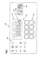
- the left third of the input and display unit 148 includes a plurality of warning and Status lights 260, the various functions of the Combine harvester 10 are assigned, but not on the present invention.
- the upper section of the middle part of the input and display unit 148 includes a graphical / numeric display 262.
- the lower section of the middle part of the input and display unit 148 includes a Variety of pressure sensitive switches 264 used can be used to select which parameters by the numeric display portion of the display 262 are displayed.
- the input and display unit 148 also includes a Speaker (not shown), the audible noise in response generated on certain conditions and operations.
- the middle part of the right third of the input and Display unit 148 includes a touch-sensitive On / off switch 266 and a touch-sensitive Learn / save switch 268, both in conjunction with the automatic control system can be used.
- the lower right Part of the display 262 includes a device management system display element 270 and a dual sequence display element 272, the both light up according to the invention, depending on the operating state, as described in more detail below.
- control unit performs 144 stored programs.
- the control unit 144 routes distance information from the speed sensor signal 154 using well-known integration techniques from.
- the programmed control unit 144 works with those in the Figures 1 and 2 shown together and implemented while the control system according to the invention.
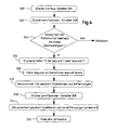
- Step 300 the automatic control system is turned on by the on / off switch 266 is pressed and the Device management system indicator 270 turns on.
- One Press the learn / save switch 268 in step 302 activates the learn / save mode and the device management system display element 270 will start flashing and on periodic beep will occur.
- Step 304 allows a continuation of the learn / save mode only if the Combine 10 is in the forward gear of the transmission 118 and faster than at a minimum speed emotional.
- the control system becomes go out of the learn / save mode and delete it and the Sequence is cleared when the operator turns off the transmission 118 switches off the forward gear.
- step 306 the operator briefly sets the switch 156 into its position for sequence 1 or sequence 2 and the corresponding sequence number of the dual sequence display element 272 will start to flash. Then the operator, as indicated at 308, a sequence manually executed Perform operations such as shifting the transmission 118 by handling the sliding lever unit 150 or a Raising or lowering the header 16 by pressing the manual operating device 146.
- the control unit 144 (at a temporary memory location) all manually performed operations along with the different ones from the combine between covered by various manual operations Distances on. Distances are based on current speeds calculated by the sensor 154 be captured and with a resolution in millimeters recorded. Distance information is only recorded when the combine is in forward gear and up moving faster than the minimum speed. The Removal may also be by means of the receiving device 158 be determined.
- step 312 the learn / save switch 268 becomes again and, as shown in step 314, stores Control unit 144 in a permanent memory, the sequence of Operations and the corresponding distances either as Sequence 1 or Sequence 2, depending on how the switch 156 previously set.
- the learn / save mode then ends in step 316 and the flashing dual sequence indicator 272 stops flashing and that alone Device management system indicator 270 remains activated.
- step 400 the on / off switch becomes 266 to turn on the system and the device management system indicator 270 is turned on.
- the step 402 allows execution mode execution when the Combine 10 is located in a forward gear of the transmission 118 and faster than at a minimum speed emotional.
- step 404 When the combine 10 is in step 404 of a location of the Fields where the operator wants a stored Sequence to perform operations, the operator moves momentarily the switch 156 in its position, that of the sequence one or the sequence two corresponds to select which one stored sequence is played, and the corresponding "1" or "2" on the dual sequence display element 272 illuminated.
- the "1" or “2" on the dual sequence display 272 is displayed for at least three seconds stay even if the running sequence is less than three Takes seconds for their execution.
- the leads Control unit 144 as indicated in step 406, automatically the selected sequence of stored operations, such as automatic shifting of the transmission 118 without one Operation of the shift lever 150 by the operator, or a automatic lifting or lowering of header 16 without the operator operates the operating device 146.
- the Operator to perform the first sequence automatically by briefly turning the switch 156 in his Position "1" spent, for example, at the end of each series of goods (or field crossing).
- the operator may enter to automatically play the second sequence by he the switch 156 briefly in its position "2" at the beginning each row (or field crossing) spends.
- control system described herein can be used a sequence of operations at the beginning of each crop row or Field crossing with a single momentary actuation of the Switch 156 and another sequence of Operations at the end of each crop row or field crossing with another single momentary actuation of the switch 156 play. Since the tax system based on the Combine 10 distances traveled instead of based on timed values, the sequences can be slow be learned when the combine is moving slowly, and automatically run faster or play when the combine harvester at normal operating speeds emotional. This gives the operator adequate time, the learning mode and to allow the control unit 144, a learn complex sequence of operations.
- a beep (beep) will occur when the on / off switch 266 is pressed.
- the contents of the stored Sequences displayed on the input and display unit 148 When a System is turned on, the contents of the stored Sequences displayed on the input and display unit 148. Each sequence, starting with sequence 1, will be every two Seconds after each learned and recorded Show event, after which "End" is displayed on the display 262 becomes.
- Learned sequences are canceled arbitrarily.
- a default maximum number such as 12 operations, can be recorded.
- the operator can get a learned Delete sequence from memory.
- the learning / saving mode is deleted during the learning process, d. H. the sequence is not was terminated normally, the sequence is out of memory deleted.
- a stored sequence may be out of memory be cleared by normal in the learn / save mode is transferred, a sequence selected, and then the Learn / save switch 268 is operated without any Functions of the combine 10 to operate. That causes the system leaves the learn / save mode and twice Sequence indicator 272 stops flashing while only the device management system indicator 270 remains on.
- the learn / save mode can also be cleared by the On / Off switch 266 is pressed and either a) within 30 seconds with the switch 156 no sequence is selected b) within 30 seconds after the switch 156 is actuated no operation was learned, c) the learn / save switch 268 not within 30 seconds of the first one learned operation is operated, d) the transmission 118 from the Forward gear is switched off, e) if the operator does not is present and the combine 10 is longer than 5 seconds not moved.
- the device management system indicator 270 in the display 262 lights up when the system is on. If the On / off switch 266 is pressed while the automatic Control system is turned on, the control system switches the automatic control and the device management system display element 270 out. When the on / off switch 266 is pressed and the switch 156 is not in the neutral position, the automatic control system is not switched on. If that Control system is in a learn / save mode when the automatic control system is turned off, the Learn / save mode cleared and no operation sequence becomes stored. When the control system executes a sequence (plays), the execution of the sequence is aborted when the automatic control system is switched off.
- a beep will occur when the learn / save switch 268 is pressed.
- the device management system display element 270 will flash during the learn mode and every two seconds controller 144 will generate a beep. If that automatic control system is not turned on, will be on Pressing the learn / save switch 268 will have no effect.
- the learning / saving switch 268 is pressed when the automatic control system is turned on, the system is in enter the learn / save mode.
- An execution of the sequence always takes place with the first operation start the sequence, even if the sequence has previously been aborted has been.
- the system always becomes one perform a learned operation. If the respective to be controlled Element is already in the status, the result of Execution of the learned operation, the system does not become Affect this element. If the operation For example, a lifting of the header 16 is the Header 16 but already fully raised, goes the Just execute on the next operation of the sequence. If the sequence is already in execution and then the switch 156 again to execute the respective active sequence is pressed, the operation of the switch 156 is ignored and the execution of the sequence is continued. When a Sequence is being executed and then the switch 156 to Execution of the other sequence is actuated, the System abort the execution of the sequence. If an item too the time a sequence is activated is, the system will not execute the sequence.
- the operator can use a clutch pedal to lock the system induce the removal during a learn / save mode to accumulate, and the automatic execution of an operation while executing a stored sequence intermittently to stop. Once 30 seconds have elapsed, the sequence becomes canceled, regardless of whether the clutch is engaged or not.
- the system will also be an execution of a Stop sequence when the gear ratio of the transmission 118 itself is above a selected maximum gear, as long as the sequence is not above the maximum gear was learned.
- the function management system of the combine 10 can the situation of the combine 10, which is the end of a Field crossing is approaching, turning around and at the beginning of a new field crossing driving back into the field, be controlled.
- the End of the field crossing can by the crop sensor 157 for an automatic activation of the automatic control system be captured or by the operator for a manual Activation of the automatic control system visually detected become. Certain features must be at the end of the field crossing be made. If the functions are automatic or manual for a sequence 1 could be the following Operations in the control unit 144 preprogrammed. Of the Header 16 is lifted by the system 141 for lifting and Lowering the header 16 raised.
- the unloading screw conveyor extension system 172 is activated to the Entladeschnecken entirelyer 54 retract and no external Touch objects when the harvester 10 for the next Field crossing turns around.
- the disconnect turn-on system 182 can be made to the clutch 212 of the rotor 28 except To engage, so that the rotor 28 does not rotate.
- the Steering system 192 can be automatically controlled to get out of the Move out and turn field to get back into the field into it down.
- the steering system 192 may also be of the Control unit 144 according to the signals of the receiving device 158 are controlled. After leaving the cut can the transmission 118 are switched to a higher gear.
- the Throttle 208 can also be operated to the Increase engine speed.
- the four-wheel drive on-off valve 204 may be actuated to lock the hydraulic motors 124a, 124b of the four-wheel drive off.
- the brakes can optionally be activated to assist steering. These automatic steps increase maneuverability, Speed, fuel efficiency and performance.
- the four-wheel drive on-off valve 204 is operated to four-wheel drive hydraulic fluid to the hydraulic motors 124a, 124b leave.
- the brakes are released.
- the throttle 208 is set to a reduced engine speed.
- the couplings 120 of the transmission 118 are driven so that in a lower, more powerful gear is switched.
- the Control of the steering system can be on a manual operation go back or for the precise movement of the combine 10 along the cutting edge according to a signal from the Receiving device 158 pass over.
- the coupling 212 of the Rotor drive can be operated to prevent rotation of the rotor 28 record.
- the separator is through the Trenn Rheinseinstellsystem 176 set. Of the Header 16 is lowered to enter the cut.
- Of the Entladeschnecken manufactureer 54 is substantially perpendicular to Direction of travel of the combine 10 extended.
- the invention is not only suitable for combine harvesters, but for any harvesters, such as forage harvesters. Instead of two Sequences can also have a higher or lower number of sequences be stored.
Landscapes
- Life Sciences & Earth Sciences (AREA)
- Environmental Sciences (AREA)
- Engineering & Computer Science (AREA)
- Mechanical Engineering (AREA)
- Soil Sciences (AREA)
- Guiding Agricultural Machines (AREA)
- Combines (AREA)
Claims (9)
- Système de commande automatique d'une moissonneuse-batteuse (10), qui comporte une barre de coupe (16), une unité conçue pour modifier la hauteur de la barre de coupe (16), une unité conçue pour modifier la vitesse d'avance de la moissonneuse-batteuse (10) et une unité de commande (144), qui est reliée par transmission de signaux avec l'unité conçue pour modifier la hauteur de la barre de coupe (16) et l'unité conçue pour modifier la vitesse d'avance de la moissonneuse-batteuse (10), l'unité de commande (144) comportant une mémoire, qui permet de modifier en fonction d'une séquence programmée la hauteur de la barre de coupe (16) et la vitesse d'avance, caractérisé en ce que l'unité de commande (144) est reliée par transmission de signaux avec un commutateur (156) qui est manoeuvré pour activer le déroulement d'une séquence programmée, en ce que le système de commande peut être amené en mode autodidactique, dans lequel il enregistre une séquence d'opérations activées manuellement par une personne de service et ensuite, en mode d'exécution, exécute la séquence, en ce que l'unité de commande (144) est reliée à un capteur de récoltes (157) qui est apte à transmettre à l'unité de commande (144) un signal de présence de récoltes, et en ce que l'unité de commande (144) est apte à faire exécuter une séquence associée à une fin d'un déplacement sur le champ lorsque la fin du déplacement sur le champ a été signalée à l'unité de commande (144) par le capteur de récoltes (157).
- Système de commande selon la revendication 1, caractérisé en ce que l'unité de commande (144) est reliée à un mécanisme de sélection d'une transmission à quatre roues motrices, lequel est apte à être commandé par la séquence.
- Système de commande selon la revendication 1 ou 2, caractérisé en ce que l'unité de commande (144) est reliée à un système de déploiement d'une vis sans fin de déchargement (172), lequel est apte à être commandé par la séquence.
- Système de commande selon l'une quelconque des revendications 1 à 3, caractérisé en ce que l'unité de commande (144) est reliée à un système de direction (192), qui est apte à être commandé par la séquence.
- Système de commande selon l'une quelconque des revendications 1 à 4, caractérisé en ce que l'unité de commande (144) est reliée à un système de freinage (195), qui est apte à être commandé par la séquence.
- Système de commande selon l'une quelconque des revendications 1 à 5, caractérisé en ce que l'unité de commande (144) est reliée à un système de réglage d'une unité de séparation (176), lequel est apte à être commandé par la séquence.
- Système de commande selon l'une quelconque des revendications 1 à 6, caractérisé en ce que l'unité de commande (144) est reliée à un dispositif destiné à coupler et découpler l'entraínement d'un dispositif rotatif de traitement des récoltes (24), lequel est apte à être commandé par la séquence.
- Système de commande selon l'une quelconque des revendications 1 à 7, caractérisé en ce que l'unité de commande (144) est reliée à un récepteur (158) destiné à recevoir les signaux d'un système de détection de position, la séquence étant lancée en tenant compte dudit récepteur.
- Système de commande selon l'une quelconque des revendications 1 à 8, caractérisé en ce que la séquence des opérations est basée sur un trajet parcouru par la moissonneuse-batteuse (10) et est indépendante de la vitesse de celle-ci.
Applications Claiming Priority (2)
| Application Number | Priority Date | Filing Date | Title |
|---|---|---|---|
| US193069 | 2002-07-11 | ||
| US10/193,069 US6681551B1 (en) | 2002-07-11 | 2002-07-11 | Programmable function control for combine |
Publications (2)
| Publication Number | Publication Date |
|---|---|
| EP1380202A1 EP1380202A1 (fr) | 2004-01-14 |
| EP1380202B1 true EP1380202B1 (fr) | 2005-10-26 |
Family
ID=29735323
Family Applications (1)
| Application Number | Title | Priority Date | Filing Date |
|---|---|---|---|
| EP03014793A Expired - Lifetime EP1380202B1 (fr) | 2002-07-11 | 2003-06-28 | Système de commande automatique d'une moissonneuse-batteuse |
Country Status (6)
| Country | Link |
|---|---|
| US (1) | US6681551B1 (fr) |
| EP (1) | EP1380202B1 (fr) |
| AR (1) | AR040486A1 (fr) |
| BR (1) | BR0302184A (fr) |
| CA (1) | CA2433894C (fr) |
| DE (1) | DE50301459D1 (fr) |
Cited By (1)
| Publication number | Priority date | Publication date | Assignee | Title |
|---|---|---|---|---|
| DE102006019216A1 (de) * | 2006-04-21 | 2007-10-25 | Claas Selbstfahrende Erntemaschinen Gmbh | Verfahren zur Steuerung eines landwirtschaftlichen Maschinensystems |
Families Citing this family (129)
| Publication number | Priority date | Publication date | Assignee | Title |
|---|---|---|---|---|
| US8639416B2 (en) | 2003-03-20 | 2014-01-28 | Agjunction Llc | GNSS guidance and machine control |
| US8594879B2 (en) * | 2003-03-20 | 2013-11-26 | Agjunction Llc | GNSS guidance and machine control |
| US9002565B2 (en) | 2003-03-20 | 2015-04-07 | Agjunction Llc | GNSS and optical guidance and machine control |
| US7404283B2 (en) * | 2003-08-06 | 2008-07-29 | Deere & Company | Crop collecting assembly for an agricultural harvester |
| DE102004013287B4 (de) * | 2004-03-18 | 2006-07-06 | Maschinenfabrik Bernard Krone Gmbh | Erntemaschine |
| US7703266B2 (en) * | 2004-04-12 | 2010-04-27 | Cnh America Llc | Method for managing the electrical control system of a windrower header flotation and lift system |
| US7869922B2 (en) * | 2004-04-12 | 2011-01-11 | Cnh America Llc | Method and apparatus to put a windrower header in the transport mode under specified conditions |
| US7555883B2 (en) * | 2004-04-12 | 2009-07-07 | Cnh America Llc | System and method for managing the electrical control system of a windrower header flotation and lift system |
| US6871483B1 (en) | 2004-06-10 | 2005-03-29 | Cnh America Llc | Header height resume |
| US7686095B2 (en) * | 2004-10-28 | 2010-03-30 | Cnh America Llc | Implement height control system |
| US7451029B2 (en) * | 2004-12-04 | 2008-11-11 | Cnh America Llc | Vehicle direction estimation using transmission control information |
| DE102004059543A1 (de) * | 2004-12-09 | 2006-06-29 | Claas Selbstfahrende Erntemaschinen Gmbh | Landwirtschaftliche Arbeitsmaschine |
| US7186201B2 (en) * | 2005-02-04 | 2007-03-06 | Cnh America Llc | Active combine rotor deceleration |
| US7226387B2 (en) * | 2005-04-01 | 2007-06-05 | Cnh America Llc | Control system for regulating a ground speed of a vehicle |
| GB0507930D0 (en) * | 2005-04-20 | 2005-06-01 | Cnh Belgium Nv | Settings control of an agricultural vehicle |
| US20060247911A1 (en) * | 2005-04-28 | 2006-11-02 | Schweitzer Engineering Labs., Inc. | Systems and methods for learning and mimicking the communications of intelligent electronic devices |
| US7121374B1 (en) * | 2005-04-30 | 2006-10-17 | Cnh America Llc | Four-wheel drive combine with slip control |
| US20070012010A1 (en) * | 2005-07-14 | 2007-01-18 | Otto Douglas R | Method and apparatus for controlling a windrower header flotation system during removal of the header |
| JP4823668B2 (ja) * | 2005-12-06 | 2011-11-24 | 日立建機株式会社 | 作業機の変速装置制御 |
| DE102006002567A1 (de) * | 2006-01-18 | 2007-08-02 | Claas Selbstfahrende Erntemaschinen Gmbh | Methode zur Erzeugung von Referenzfahrspuren für landwirtschaftliche Fahrzeuge |
| US7743591B2 (en) * | 2006-02-10 | 2010-06-29 | Syngenta Participations, Ag | Research plot harvester for continuous plot to plot grain evaluation |
| US20070294990A1 (en) * | 2006-06-26 | 2007-12-27 | Deere & Company, A Delaware Corporation. | Locking harvester header lift cylinder |
| JP2008013111A (ja) * | 2006-07-07 | 2008-01-24 | Denso Corp | 車両機器自動操作装置 |
| US7747370B2 (en) * | 2007-04-03 | 2010-06-29 | Cnh America Llc | Method for creating end of row turns for agricultural vehicles |
| US7802956B2 (en) * | 2007-05-22 | 2010-09-28 | Schertz Scott F | Apparatus for automatically unloading agricultural material from a storage bag |
| US8209075B2 (en) * | 2007-07-31 | 2012-06-26 | Deere & Company | Method and system for generating end turns |
| US7739015B2 (en) * | 2007-07-31 | 2010-06-15 | Deere & Company | System and method for controlling a vehicle with a sequence of vehicle events |
| US8635011B2 (en) | 2007-07-31 | 2014-01-21 | Deere & Company | System and method for controlling a vehicle in response to a particular boundary |
| US7729835B2 (en) * | 2007-08-21 | 2010-06-01 | Jcb Compact Products Limited | Method of controlling a working machine |
| DE102007046678A1 (de) * | 2007-09-27 | 2009-04-09 | Claas Selbstfahrende Erntemaschinen Gmbh | Landwirtschaftliches Arbeitsfahrzeug |
| US9037355B2 (en) * | 2007-11-05 | 2015-05-19 | Deere & Company | Control assembly for auxiliary hydraulics |
| US20090127011A1 (en) * | 2007-11-21 | 2009-05-21 | Yisheng Zhang | Control method for optimizing the operation of a hybrid drive system |
| US8131432B2 (en) * | 2008-02-27 | 2012-03-06 | Deere & Company | Method and system for managing the turning of a vehicle |
| DE102008014001A1 (de) † | 2008-03-13 | 2009-09-17 | Claas Selbstfahrende Erntemaschinen Gmbh | Landwirtschaftliche Erntemaschine mit einer Überladeeinrichtung |
| US8204654B2 (en) * | 2008-03-20 | 2012-06-19 | Deere & Company | System and method for generation of an inner boundary of a work area |
| US7748489B2 (en) * | 2008-10-31 | 2010-07-06 | Deere & Company | Agricultural header presence sensor with traction control |
| US20100287898A1 (en) * | 2009-05-18 | 2010-11-18 | Cnh America, Llc | Ground speed implement height control adjustment rate on agricultural vehicles |
| US8010262B2 (en) * | 2009-10-21 | 2011-08-30 | Cnh America Llc | Apparatus and method for automatically controlling the settings of an adjustable crop residue spreader of an agricultural combine |
| US8220235B2 (en) * | 2010-01-19 | 2012-07-17 | Cnh America Llc | Corn head stripper plate adjusting mechanism |
| US8333057B2 (en) | 2011-01-06 | 2012-12-18 | Cnh America Llc | Automatic header lateral tilt to ground speed response |
| DE102011054630A1 (de) * | 2011-10-20 | 2013-04-25 | Claas Agrosystems GmbH | Visualisierungseinrichtung |
| US8745964B2 (en) * | 2011-11-16 | 2014-06-10 | Macdon Industries Ltd | Swather with float assembly and disconnect coupling |
| DE102011121433A1 (de) * | 2011-12-16 | 2013-06-20 | Robert Bosch Gmbh | Verfahren und Vorrichtung zur Ansteuerung einer Landmaschine |
| US9763385B2 (en) | 2012-08-08 | 2017-09-19 | Cnh Industrial America Llc | Automatic control of relative positioning of the cutter bar and reel |
| DE102013100793A1 (de) * | 2013-01-28 | 2014-07-31 | Usines Claas France S.A.S. | Kombination aus einem Zugfahrzeug und einer davon gezogenen landwirtschaftlichen Erntemaschine |
| US9811087B2 (en) * | 2013-05-15 | 2017-11-07 | Deere & Company | Method for controlling a vehicle and a vehicle guidance system |
| US9458600B2 (en) | 2013-05-15 | 2016-10-04 | Deere & Company | Method for controlling an implement associated with a vehicle |
| US10531607B2 (en) * | 2013-07-31 | 2020-01-14 | Cnh Industrial America Llc | Header lateral tilt control with automatic operation in free float and controlled tilt modes |
| UA122201C2 (uk) * | 2014-04-01 | 2020-10-12 | Зе Клаймат Корпорейшн | Спосіб поточного контролю продуктивності праці оператора сільськогосподарської техніки |
| DE102014105820A1 (de) * | 2014-04-25 | 2015-10-29 | Usines Claas France S.A.S. | Kombination aus einem Zugfahrzeug und einer davon gezogenen Erntemaschine |
| US10407072B2 (en) | 2015-09-03 | 2019-09-10 | Deere & Company | System and method of regulating wheel slip in a traction vehicle |
| US10112615B2 (en) * | 2015-09-03 | 2018-10-30 | Deere & Company | System and method of reacting to wheel slip in a traction vehicle |
| US9994104B2 (en) | 2015-09-03 | 2018-06-12 | Deere & Company | System and method of reacting to wheel slip in a traction vehicle |
| DE102016111665A1 (de) | 2016-06-24 | 2017-12-28 | Claas Selbstfahrende Erntemaschinen Gmbh | Landwirtschaftliche Arbeitsmaschine und Verfahren zum Betrieb einer landwirtschaftlichen Arbeitsmaschine |
| EP3406120B1 (fr) * | 2017-05-24 | 2019-12-11 | Kverneland Group Mechatronics BV | Procédé pour commander le fonctionnement d'un terminal de commande utilisateur d'une machine agricole et machine agricole |
| US10436624B2 (en) | 2017-08-23 | 2019-10-08 | Federal Signal Corporation | Water level monitoring for multiple water tanks of sewer cleaning vehicle |
| US10863672B2 (en) | 2017-11-06 | 2020-12-15 | Deere & Company | Radio frequency measurement device for measuring harvested agricultural material |
| US10871458B2 (en) | 2017-11-06 | 2020-12-22 | Deere & Company | Radio frequency measurement device for measuring grain loss |
| US10802699B2 (en) | 2017-11-30 | 2020-10-13 | Federal Signal Corporation | Service mode selection system for service vehicle |
| US11279400B1 (en) | 2018-01-02 | 2022-03-22 | RBR Enterprise, LLC | Adjustable wheel track axle with independent wheel angle control for an agricultural vehicle |
| US10808839B2 (en) | 2018-01-24 | 2020-10-20 | Cnh Industrial America Llc | Method and system for controlling a hydrostatic drive system of an agricultural vehicle |
| US11089727B2 (en) * | 2018-02-23 | 2021-08-17 | Macdon Industries | Harvesting machine with programmable inputs for header height and auxiliary function control |
| US10806079B2 (en) | 2018-02-26 | 2020-10-20 | Deere & Company | Automatic product harvesting method and control system |
| DE102018212834A1 (de) | 2018-08-01 | 2020-02-06 | Deere & Company | Anordnung zur selbsttätigen Kontrolle des Antriebs eines seitlich an einem Erntevorsatz angebrachten Elements, das zur Aufteilung des Ernteguts an der Grenze zwischen stehen bleibendem und abzuerntenden Bestand dient |
| US11079725B2 (en) | 2019-04-10 | 2021-08-03 | Deere & Company | Machine control using real-time model |
| US11467605B2 (en) | 2019-04-10 | 2022-10-11 | Deere & Company | Zonal machine control |
| US11641800B2 (en) | 2020-02-06 | 2023-05-09 | Deere & Company | Agricultural harvesting machine with pre-emergence weed detection and mitigation system |
| US11589509B2 (en) | 2018-10-26 | 2023-02-28 | Deere & Company | Predictive machine characteristic map generation and control system |
| US11957072B2 (en) | 2020-02-06 | 2024-04-16 | Deere & Company | Pre-emergence weed detection and mitigation system |
| US11653588B2 (en) | 2018-10-26 | 2023-05-23 | Deere & Company | Yield map generation and control system |
| US11672203B2 (en) | 2018-10-26 | 2023-06-13 | Deere & Company | Predictive map generation and control |
| US12069978B2 (en) | 2018-10-26 | 2024-08-27 | Deere & Company | Predictive environmental characteristic map generation and control system |
| DE102018218442A1 (de) | 2018-10-29 | 2020-04-30 | Deere & Company | Anordnung zur Steuerung des Betriebs eines Bandschneidwerks |
| US11234366B2 (en) | 2019-04-10 | 2022-02-01 | Deere & Company | Image selection for machine control |
| US11778945B2 (en) | 2019-04-10 | 2023-10-10 | Deere & Company | Machine control using real-time model |
| US11178804B2 (en) | 2019-06-04 | 2021-11-23 | Cnh Industrial America Llc | Ground engaging tool positioning system |
| CN110419320B (zh) * | 2019-08-16 | 2023-10-10 | 中联重机南陵有限公司 | 联合收割机卸粮筒回位控制系统及方法、联合收割机 |
| US11997947B2 (en) | 2019-12-23 | 2024-06-04 | Cnh Industrial America Llc | System and method for setting a profile of a header during a non-harvesting mode |
| US12225846B2 (en) | 2020-02-06 | 2025-02-18 | Deere & Company | Machine control using a predictive map |
| US12329148B2 (en) | 2020-02-06 | 2025-06-17 | Deere & Company | Predictive weed map and material application machine control |
| US12035648B2 (en) | 2020-02-06 | 2024-07-16 | Deere & Company | Predictive weed map generation and control system |
| US11452259B2 (en) | 2020-03-17 | 2022-09-27 | Cnh Industrial America Llc | System and method for controlling harvester implement position of an agricultural harvester |
| US11477940B2 (en) | 2020-03-26 | 2022-10-25 | Deere & Company | Mobile work machine control based on zone parameter modification |
| DE102020119291A1 (de) | 2020-07-22 | 2022-01-27 | Deere & Company | Antriebssystem für eine Erntemaschine |
| US11635765B2 (en) | 2020-10-09 | 2023-04-25 | Deere & Company | Crop state map generation and control system |
| US12422847B2 (en) | 2020-10-09 | 2025-09-23 | Deere & Company | Predictive agricultural model and map generation |
| US11849671B2 (en) | 2020-10-09 | 2023-12-26 | Deere & Company | Crop state map generation and control system |
| US11650587B2 (en) | 2020-10-09 | 2023-05-16 | Deere & Company | Predictive power map generation and control system |
| US11927459B2 (en) | 2020-10-09 | 2024-03-12 | Deere & Company | Machine control using a predictive map |
| US12178158B2 (en) | 2020-10-09 | 2024-12-31 | Deere & Company | Predictive map generation and control system for an agricultural work machine |
| US11825768B2 (en) | 2020-10-09 | 2023-11-28 | Deere & Company | Machine control using a predictive map |
| US11711995B2 (en) | 2020-10-09 | 2023-08-01 | Deere & Company | Machine control using a predictive map |
| US11889788B2 (en) | 2020-10-09 | 2024-02-06 | Deere & Company | Predictive biomass map generation and control |
| US11727680B2 (en) | 2020-10-09 | 2023-08-15 | Deere & Company | Predictive map generation based on seeding characteristics and control |
| US11849672B2 (en) | 2020-10-09 | 2023-12-26 | Deere & Company | Machine control using a predictive map |
| US11871697B2 (en) | 2020-10-09 | 2024-01-16 | Deere & Company | Crop moisture map generation and control system |
| US12550802B2 (en) | 2020-10-08 | 2026-02-17 | Deere & Company | Predictive machine characteristic map generation and control system |
| US12069986B2 (en) | 2020-10-09 | 2024-08-27 | Deere & Company | Map generation and control system |
| US11864483B2 (en) | 2020-10-09 | 2024-01-09 | Deere & Company | Predictive map generation and control system |
| US11844311B2 (en) | 2020-10-09 | 2023-12-19 | Deere & Company | Machine control using a predictive map |
| US11675354B2 (en) | 2020-10-09 | 2023-06-13 | Deere & Company | Machine control using a predictive map |
| US11895948B2 (en) | 2020-10-09 | 2024-02-13 | Deere & Company | Predictive map generation and control based on soil properties |
| US11592822B2 (en) | 2020-10-09 | 2023-02-28 | Deere & Company | Machine control using a predictive map |
| US12013245B2 (en) | 2020-10-09 | 2024-06-18 | Deere & Company | Predictive map generation and control system |
| US11845449B2 (en) | 2020-10-09 | 2023-12-19 | Deere & Company | Map generation and control system |
| US11874669B2 (en) | 2020-10-09 | 2024-01-16 | Deere & Company | Map generation and control system |
| US11983009B2 (en) | 2020-10-09 | 2024-05-14 | Deere & Company | Map generation and control system |
| US11946747B2 (en) | 2020-10-09 | 2024-04-02 | Deere & Company | Crop constituent map generation and control system |
| US12419220B2 (en) | 2020-10-09 | 2025-09-23 | Deere & Company | Predictive map generation and control system |
| US12386354B2 (en) | 2020-10-09 | 2025-08-12 | Deere & Company | Predictive power map generation and control system |
| US11474523B2 (en) | 2020-10-09 | 2022-10-18 | Deere & Company | Machine control using a predictive speed map |
| US12250905B2 (en) | 2020-10-09 | 2025-03-18 | Deere & Company | Machine control using a predictive map |
| US11889787B2 (en) | 2020-10-09 | 2024-02-06 | Deere & Company | Predictive speed map generation and control system |
| US12127500B2 (en) | 2021-01-27 | 2024-10-29 | Deere & Company | Machine control using a map with regime zones |
| US20220394927A1 (en) * | 2021-06-15 | 2022-12-15 | Cnh Industrial America Llc | System and method for steering a harvesting implement of an agricultural harvester |
| US12089529B2 (en) | 2021-07-22 | 2024-09-17 | Cnh Industrial America Llc | System and method for controlling crop unloading tube position of an agricultural harvester |
| DE102021119897A1 (de) * | 2021-07-30 | 2023-02-02 | Claas Selbstfahrende Erntemaschinen Gmbh | Landwirtschaftliche Maschine mit schwingungsgedämpftem Vorsatzgerät |
| US11903344B2 (en) | 2021-11-16 | 2024-02-20 | Cnh Industrial America Llc | System and method for controlling unloading system position of an agricultural harvester |
| US12302791B2 (en) | 2021-12-20 | 2025-05-20 | Deere & Company | Crop constituents, predictive mapping, and agricultural harvester control |
| US12245549B2 (en) | 2022-01-11 | 2025-03-11 | Deere & Company | Predictive response map generation and control system |
| CN114342645A (zh) * | 2022-01-24 | 2022-04-15 | 潍柴雷沃重工股份有限公司 | 均布搅龙控制方法、系统、装置、介质、设备及收割机 |
| US12520759B2 (en) | 2022-01-26 | 2026-01-13 | Deere & Company | Systems and methods for predicting material dynamics |
| US12082531B2 (en) | 2022-01-26 | 2024-09-10 | Deere & Company | Systems and methods for predicting material dynamics |
| US12295288B2 (en) | 2022-04-05 | 2025-05-13 | Deere &Company | Predictive machine setting map generation and control system |
| US12358493B2 (en) | 2022-04-08 | 2025-07-15 | Deere & Company | Systems and methods for predictive power requirements and control |
| US12284934B2 (en) | 2022-04-08 | 2025-04-29 | Deere & Company | Systems and methods for predictive tractive characteristics and control |
| US12058951B2 (en) | 2022-04-08 | 2024-08-13 | Deere & Company | Predictive nutrient map and control |
| US12298767B2 (en) | 2022-04-08 | 2025-05-13 | Deere & Company | Predictive material consumption map and control |
| US12582035B2 (en) | 2022-04-08 | 2026-03-24 | Deere & Company | Systems and methods for predictive power requirements and control |
Family Cites Families (15)
| Publication number | Priority date | Publication date | Assignee | Title |
|---|---|---|---|---|
| US4663921A (en) | 1982-04-23 | 1987-05-12 | Deere & Company | Combine harvester with header-mounted separator |
| US4450671A (en) | 1982-06-01 | 1984-05-29 | Deere & Company | Combine harvester with modified feeder house |
| JPS59118929A (ja) | 1982-12-24 | 1984-07-09 | Kubota Ltd | 掘削作業車 |
| US4967544A (en) | 1989-01-05 | 1990-11-06 | Deere & Company | Automatic speed control system for a harvesting assembly |
| AU676037B2 (en) | 1993-07-01 | 1997-02-27 | Deere & Company | An axial flow combine having a concentric threshing section and an eccentric separation section |
| US5688170A (en) | 1993-07-01 | 1997-11-18 | Deere & Company | Rotary combine having a concentric infeed section and eccentric threshing and separating sections |
| US5469694A (en) | 1994-06-24 | 1995-11-28 | Case Corporation | Agricultural vehicle including a system for automatically moving an implement to a predetermined operating position |
| DE4431824C1 (de) | 1994-09-07 | 1996-05-02 | Claas Ohg | Mähdrescherbetrieb mit Betriebsdatenkataster |
| DE19506059A1 (de) | 1995-02-22 | 1996-08-29 | Deere & Co | Verfahren zur automatischen Regelung wenigstens eines Abschnitts der Gutbearbeitung in einer Erntemaschine |
| FR2764401B1 (fr) * | 1997-06-04 | 1999-09-10 | Renault Agriculture | Procede d'automatisation des taches repetitives sur un engin et dispositif correspondant |
| US5995895A (en) | 1997-07-15 | 1999-11-30 | Case Corporation | Control of vehicular systems in response to anticipated conditions predicted using predetermined geo-referenced maps |
| US6131062A (en) | 1999-01-21 | 2000-10-10 | Case Corporation | Apparatus and method for preventing an automatic operation sequence in a work vehicle |
| US6292729B2 (en) | 1999-04-14 | 2001-09-18 | Deere & Company | Vehicle function management system |
| US6257977B1 (en) | 1999-08-20 | 2001-07-10 | Deere & Company | Rotary combine having a rotor axis divergent from a rotor housing axis |
| GB0128803D0 (en) * | 2001-12-03 | 2002-01-23 | New Holland Uk Ltd | Agricultural vehicle |
-
2002
- 2002-07-11 US US10/193,069 patent/US6681551B1/en not_active Expired - Lifetime
-
2003
- 2003-06-26 CA CA002433894A patent/CA2433894C/fr not_active Expired - Lifetime
- 2003-06-28 DE DE50301459T patent/DE50301459D1/de not_active Expired - Lifetime
- 2003-06-28 EP EP03014793A patent/EP1380202B1/fr not_active Expired - Lifetime
- 2003-07-10 BR BR0302184-0A patent/BR0302184A/pt not_active Application Discontinuation
- 2003-07-10 AR AR20030102494A patent/AR040486A1/es active IP Right Grant
Cited By (1)
| Publication number | Priority date | Publication date | Assignee | Title |
|---|---|---|---|---|
| DE102006019216A1 (de) * | 2006-04-21 | 2007-10-25 | Claas Selbstfahrende Erntemaschinen Gmbh | Verfahren zur Steuerung eines landwirtschaftlichen Maschinensystems |
Also Published As
| Publication number | Publication date |
|---|---|
| US20040006957A1 (en) | 2004-01-15 |
| EP1380202A1 (fr) | 2004-01-14 |
| CA2433894C (fr) | 2007-01-09 |
| US6681551B1 (en) | 2004-01-27 |
| CA2433894A1 (fr) | 2004-01-11 |
| DE50301459D1 (de) | 2005-12-01 |
| AR040486A1 (es) | 2005-04-06 |
| BR0302184A (pt) | 2004-09-08 |
Similar Documents
| Publication | Publication Date | Title |
|---|---|---|
| EP1380202A1 (fr) | Système de commande automatique d'une moissonneuse-batteuse | |
| EP1044591B1 (fr) | Système de gestion de la fonction pour véhicules | |
| EP2345320B1 (fr) | Récolteuse automobile | |
| EP2936969B1 (fr) | Combinaison d'un véhicule de traction et d'une moissonneuse tirée par celui-ci | |
| EP1046334B1 (fr) | Dispositif d'entraínement du convoyeur et/ou du dispositif de traitement de récolte | |
| EP1683407B1 (fr) | Système d'entraînement pour machine agricole | |
| EP1350658B1 (fr) | Système d'entraînement pour véhicule utilitaire | |
| EP0168665B1 (fr) | Dispositif à andains montée à l'arrière d'une moissonneuse | |
| RU2528953C2 (ru) | Сельскохозяйственная уборочная машина с запуском изменения направлений движения ленточной платформенной жатки, гидравлический рычаг и способ управления работой платформенной жатки | |
| DE19918552A1 (de) | Erntemaschine | |
| EP2574229B1 (fr) | Moissonneuse agricole automobile dotée d'un accessoire de récolte articulé autour d'un axe vertical | |
| EP1668975B1 (fr) | Machine de travail automoteur | |
| EP1219153A2 (fr) | Dispositif et méthode pour coordonner et contrôler des véhicules agricoles | |
| DE102013101444A1 (de) | Verfahren zum Betreiben einer selbstfahrenden Erntemaschine sowie selbstfahrende Erntemaschine | |
| EP3259975B1 (fr) | Engin agricole et procédé de fonctionnement d'un engin agricole | |
| EP2308281A2 (fr) | Moissonneuse | |
| BE1028458B1 (de) | Antriebssystem für eine Erntemaschine | |
| EP1570724B1 (fr) | Disposition d'actionnement pour actionner la tête de récolte d'une machine de récolte | |
| EP1523872B2 (fr) | Machine de travail agricole | |
| DE102014201092B4 (de) | Lenkeinrichtung für eine selbstfahrende Erntemaschine | |
| EP2132975A1 (fr) | Système d'entraînement pour une moissonneuse | |
| DE2451314A1 (de) | Landwirtschaftlich genutztes fahrzeug mit einer vorrichtung zur automatischen durchfuehrung von teilarbeitsablaeufen | |
| JP2579757B2 (ja) | 作業車輌における走行制御装置 | |
| JPH0576229U (ja) | 作業車輌における走行制御装置 | |
| JPH064674Y2 (ja) | 作業車輌における走行制御装置 |
Legal Events
| Date | Code | Title | Description |
|---|---|---|---|
| PUAI | Public reference made under article 153(3) epc to a published international application that has entered the european phase |
Free format text: ORIGINAL CODE: 0009012 |
|
| AK | Designated contracting states |
Kind code of ref document: A1 Designated state(s): AT BE BG CH CY CZ DE DK EE ES FI FR GB GR HU IE IT LI LU MC NL PT RO SE SI SK TR |
|
| AX | Request for extension of the european patent |
Extension state: AL LT LV MK |
|
| 17P | Request for examination filed |
Effective date: 20040714 |
|
| AKX | Designation fees paid |
Designated state(s): BE DE FR GB IT |
|
| 17Q | First examination report despatched |
Effective date: 20041029 |
|
| GRAP | Despatch of communication of intention to grant a patent |
Free format text: ORIGINAL CODE: EPIDOSNIGR1 |
|
| GRAS | Grant fee paid |
Free format text: ORIGINAL CODE: EPIDOSNIGR3 |
|
| GRAA | (expected) grant |
Free format text: ORIGINAL CODE: 0009210 |
|
| AK | Designated contracting states |
Kind code of ref document: B1 Designated state(s): BE DE FR GB IT |
|
| REG | Reference to a national code |
Ref country code: GB Ref legal event code: FG4D Free format text: NOT ENGLISH |
|
| REF | Corresponds to: |
Ref document number: 50301459 Country of ref document: DE Date of ref document: 20051201 Kind code of ref document: P |
|
| GBT | Gb: translation of ep patent filed (gb section 77(6)(a)/1977) |
Effective date: 20051205 |
|
| ET | Fr: translation filed | ||
| PLBE | No opposition filed within time limit |
Free format text: ORIGINAL CODE: 0009261 |
|
| STAA | Information on the status of an ep patent application or granted ep patent |
Free format text: STATUS: NO OPPOSITION FILED WITHIN TIME LIMIT |
|
| 26N | No opposition filed |
Effective date: 20060727 |
|
| PGFP | Annual fee paid to national office [announced via postgrant information from national office to epo] |
Ref country code: GB Payment date: 20140627 Year of fee payment: 12 |
|
| PGFP | Annual fee paid to national office [announced via postgrant information from national office to epo] |
Ref country code: IT Payment date: 20140624 Year of fee payment: 12 |
|
| PGFP | Annual fee paid to national office [announced via postgrant information from national office to epo] |
Ref country code: FR Payment date: 20140617 Year of fee payment: 12 |
|
| PG25 | Lapsed in a contracting state [announced via postgrant information from national office to epo] |
Ref country code: IT Free format text: LAPSE BECAUSE OF NON-PAYMENT OF DUE FEES Effective date: 20150628 |
|
| GBPC | Gb: european patent ceased through non-payment of renewal fee |
Effective date: 20150628 |
|
| REG | Reference to a national code |
Ref country code: FR Ref legal event code: ST Effective date: 20160229 |
|
| PG25 | Lapsed in a contracting state [announced via postgrant information from national office to epo] |
Ref country code: GB Free format text: LAPSE BECAUSE OF NON-PAYMENT OF DUE FEES Effective date: 20150628 |
|
| PG25 | Lapsed in a contracting state [announced via postgrant information from national office to epo] |
Ref country code: FR Free format text: LAPSE BECAUSE OF NON-PAYMENT OF DUE FEES Effective date: 20150630 |
|
| PGFP | Annual fee paid to national office [announced via postgrant information from national office to epo] |
Ref country code: BE Payment date: 20190627 Year of fee payment: 17 |
|
| REG | Reference to a national code |
Ref country code: DE Ref legal event code: R084 Ref document number: 50301459 Country of ref document: DE |
|
| REG | Reference to a national code |
Ref country code: BE Ref legal event code: MM Effective date: 20200630 |
|
| PG25 | Lapsed in a contracting state [announced via postgrant information from national office to epo] |
Ref country code: BE Free format text: LAPSE BECAUSE OF NON-PAYMENT OF DUE FEES Effective date: 20200630 |
|
| PGFP | Annual fee paid to national office [announced via postgrant information from national office to epo] |
Ref country code: DE Payment date: 20220519 Year of fee payment: 20 |
|
| REG | Reference to a national code |
Ref country code: DE Ref legal event code: R071 Ref document number: 50301459 Country of ref document: DE |