EP1044598B1 - Entrainement pour le dispositif de battage de moissonneuses-batteuses - Google Patents
Entrainement pour le dispositif de battage de moissonneuses-batteuses Download PDFInfo
- Publication number
- EP1044598B1 EP1044598B1 EP00108376A EP00108376A EP1044598B1 EP 1044598 B1 EP1044598 B1 EP 1044598B1 EP 00108376 A EP00108376 A EP 00108376A EP 00108376 A EP00108376 A EP 00108376A EP 1044598 B1 EP1044598 B1 EP 1044598B1
- Authority
- EP
- European Patent Office
- Prior art keywords
- drum
- threshing
- drive
- drums
- threshing device
- Prior art date
- Legal status (The legal status is an assumption and is not a legal conclusion. Google has not performed a legal analysis and makes no representation as to the accuracy of the status listed.)
- Revoked
Links
- 239000010902 straw Substances 0.000 claims description 11
- 230000007246 mechanism Effects 0.000 claims description 9
- 239000002131 composite material Substances 0.000 claims description 4
- 230000008878 coupling Effects 0.000 claims description 4
- 238000010168 coupling process Methods 0.000 claims description 4
- 238000005859 coupling reaction Methods 0.000 claims description 4
- 230000005540 biological transmission Effects 0.000 claims description 3
- 230000002093 peripheral effect Effects 0.000 description 15
- 239000000463 material Substances 0.000 description 10
- 230000008859 change Effects 0.000 description 4
- 238000004519 manufacturing process Methods 0.000 description 3
- 238000000926 separation method Methods 0.000 description 3
- 230000009467 reduction Effects 0.000 description 2
- 230000002441 reversible effect Effects 0.000 description 2
- 238000011144 upstream manufacturing Methods 0.000 description 2
- 244000105624 Arachis hypogaea Species 0.000 description 1
- 206010010774 Constipation Diseases 0.000 description 1
- 241000208818 Helianthus Species 0.000 description 1
- 235000003222 Helianthus annuus Nutrition 0.000 description 1
- 241001124569 Lycaenidae Species 0.000 description 1
- 244000046052 Phaseolus vulgaris Species 0.000 description 1
- 235000010627 Phaseolus vulgaris Nutrition 0.000 description 1
- 235000010582 Pisum sativum Nutrition 0.000 description 1
- 240000004713 Pisum sativum Species 0.000 description 1
- 241001272996 Polyphylla fullo Species 0.000 description 1
- 240000008042 Zea mays Species 0.000 description 1
- 235000005824 Zea mays ssp. parviglumis Nutrition 0.000 description 1
- 235000002017 Zea mays subsp mays Nutrition 0.000 description 1
- 230000000712 assembly Effects 0.000 description 1
- 238000000429 assembly Methods 0.000 description 1
- 230000015572 biosynthetic process Effects 0.000 description 1
- 235000005822 corn Nutrition 0.000 description 1
- 238000010586 diagram Methods 0.000 description 1
- 238000003306 harvesting Methods 0.000 description 1
- 238000000034 method Methods 0.000 description 1
- 235000020232 peanut Nutrition 0.000 description 1
- 230000008569 process Effects 0.000 description 1
Images


Classifications
-
- A—HUMAN NECESSITIES
- A01—AGRICULTURE; FORESTRY; ANIMAL HUSBANDRY; HUNTING; TRAPPING; FISHING
- A01F—PROCESSING OF HARVESTED PRODUCE; HAY OR STRAW PRESSES; DEVICES FOR STORING AGRICULTURAL OR HORTICULTURAL PRODUCE
- A01F12/00—Parts or details of threshing apparatus
- A01F12/56—Driving mechanisms for the threshing parts
Definitions
- the invention relates to a threshing device of a combine harvester with drive for its multi-drum threshing system working in tangential flow according to the features in the preamble of the first claim.
- the TX combine harvester for example, has such a threshing device the models "TX 62 to TX 68" from the American company NEW HOLLAND, which are printed in the brochure with the "50122 / DOO - Printed in Italy - 09/95 "are presented.
- the threshing drum is followed by a guide drum, their main function in the forwarding of the threshing material to the following Centrifugal separator is. This takes another threshing before and then passes the threshing material to the Quattrotrommel, which it targets the first stage of the shaker.
- the drive guide is designed here so that a countershaft from the engine output is driven, on which the driving disk of a variator is attached.
- the driven variator disc sits directly on the shaft of the threshing drum.
- the gearbox comes in Another belt drive to the separating drum, the one for realizing two different speeds for the separating drum on adjacent pulleys is reversible with the reverse gear ratio.
- One of the Separating drum outgoing further belt drive with constant transmission ratio serves to drive the Quattrotrommel.
- the threshing drum and the guide drum run through this drive guide with equally varied peripheral speeds when the variator is adjusted.
- the change in peripheral speeds is the separating drum and quattro drum also running constantly with respect to each other only in a changeover stage by moving the belt as described above possible on the adjacent pulleys.
- a disadvantage of this drive guide is that the flow of the threshed material through the threshing device due to different peripheral speeds the drums are not optimal. If the separation drum and the. Quattrotrommel run too fast compared to the threshing drum and guide drum, too much short straw arises and grain breakage occurs. Run against it too slow, there are constant blockages in the rear part of the threshing unit and the separating drum no longer separates the grain properly. Moreover is the amount of working time for switching the belt drive between the Gear and the separation drum too high.
- a multi-drum system of a threshing device is in the "TOPLINER 8 XL" combine harvester from Germany
- the DEUTZ-FAHR company the new brochure about DEUTZ-FAHR 97/98 with the print reference "91 098 01 Printed in Germany 9709" is shown.
- the threshing drum is a guide drum and this is a separating drum downstream.
- the last drum, called the distribution drum Threshing device distributes the straw to the straw walkers that are wider than that Threshing device are formed.
- the drive guidance of this threshing device starts at the engine output, from which is driven by a first intermediate shaft via a first belt drive and from the latter via a so-called main drive belt second intermediate shaft.
- On the right hand side of the the second intermediate shaft is the driving disk of a variator and the driven disc is attached to a countershaft. From the countershaft a belt drive drives out with the interposition if necessary the threshing drum of a reduction gear.
- On the left side of the Threshing drum returns a belt drive with constant gear ratio to Beater.
- variable-diameter variator disc sits on the shaft of the separation drum and drives them at variable speeds. Also on the left is the distributor drum with the separating drum with a belt drive constant gear ratio.
- the invention has for its object to be a threshing device of a combine with drive for To create tangential flow working multi-drum threshing system that over the whole range of different peripheral speeds of the Drum an optimal flow of the threshed material through the threshing device guaranteed where there is no working time to change the peripheral speeds the drums is required at the misalignment for the optimal peripheral speed for threshing a wide variety of crop types are excluded by the operator and which are inexpensive in the Manufacturing is.
- a third variant of a multi-drum system a threshing device of a drawn combine mainly for harvesting peanuts according to US Pat. No. 4,205,508, the with a lower threshing drum, a central or transfer drum and one rear threshing drum.
- These drums are through chain drives with each other in constant gear ratios connected. They are driven by the PTO rotating at a constant speed of a towing vehicle via a cardan shaft, a transverse shaft and one itself subsequent chain drive jointly driven. That of the threshing device upstream pick-up receives its drive at average driving speeds via another chain drive from the lower threshing drum, which means they, like so-called drums, have a constant peripheral speed rotates.
- a suitable variable-speed drive mechanism ensures that all drums thresh the threshing material at the peripheral speed or forward that for a gentle and complete threshing of the respective threshing material is necessary.
- variable-speed drive mechanism it provides for the formation of the variable-speed drive mechanism to use a variator drive, which if necessary in combination with a reduction gear is capable of all peripheral speeds that are optimal for threshing goods provide.
- a tried and tested solution for driving the threshing device drums consists in introducing the drive power into the threshing drum, because this for the threshing process alone well over half that for the threshing device available power consumed.
- To forward the remaining drive power to the leading, separating and straw drums has proven to be useful due to its low power consumption, to drive the neighboring drums one after the other.
- the threshing drum is with the guide drum, the guide drum with the separating drum and the separating drum is drivingly connected to the straw drum.
- the power consumption of the drums downstream of the threshing drum is still relatively small in total.
- a conceivable embodiment of the invention is also seen when in a generic threshing device of the threshing drum one or more Drums are upstream and there the drive design according to the invention is realized. Even then it would be advisable to use the entire drive power into the threshing drum and from there to the others Distribute drums.
- the advantages of the invention are such that the drive according to the invention for the threshing device an optimal flow of the threshed material through the threshing device over the entire area of the different peripheral speeds is guaranteed. Because to change the peripheral speeds of the drums only the variable speed Actuating the drive mechanism means that there is no labor involved on. Furthermore, there are also operating errors when changing the Circumferential speeds excluded, which lead to increased short straw proportions, Loss of grain or constipation. After all, this is the drive due to its simplicity, inexpensive to manufacture.
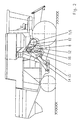
- the combine harvester has a tangential flow Working 4-drum threshing system that works in the direction of flow of the threshed material seen a threshing drum 1, a guide drum 2, a separating drum 3 and has a straw drum 4. All drums 5 work together with the other components belonging to the threshing device an effective and gentle threshing of various crops, their peripheral speed adaptable to the properties of the crops via the drive system is.
- the drive system is designed here so that the on the left side of the Combine located engine output 6 a composite V-belt 7 to a Intermediate shaft 8 leads, which can be engaged and disengaged via a belt coupling 9 is. Due to its considerable length, the belt coupling is 9 a guide roller 10 supporting the composite V-belt 7 from the inside is provided.
- the intermediate shaft 8 goes through the combine and you right end serves to accommodate a variable-speed drive mechanism 11.
- it is the drive pulley 12 of a variator drive 13
- the driven disk 14 part of one on the combine harvester frame attached countershaft 15 is of a rotationally fixed with the driven pulley 14 connected pulley 16 carries another composite V-belt 17 directly to the threshing drum 1.
- On the left side of the combine there are further narrow V-belt sets 18 that the threshing drum 1 with the guide drum 2, the guide drum 2 with the separating drum 3 and the separating drum 3 drive-connected to the straw drum 4.
Landscapes
- Life Sciences & Earth Sciences (AREA)
- Environmental Sciences (AREA)
- Threshing Machine Elements (AREA)
Claims (5)
- Dispositif de battage d'une moissonneuse-batteuse avec entraínement pour son système de battage à tambours multiples fonctionnant dans un flux tangentiel, comprenant au moins quatre tambours, caractérisé en ce que tous les tambours (5) restent dans des rapports de démultiplication constants les uns avec les autres dans une liaison conforme à l'entraínement et en ce que leur entraínement s'effectue via un mécanisme d'entraínement (11) à vitesse variable.
- Dispositif de battage selon la revendication 1, caractérisé en ce que le mécanisme d'entraínement à vitesse variable (11) est conçu comme une commande d'engrenage à vitesse variable (13).
- Dispositif de battage selon les revendications 1 et 2, caractérisé en ce que le mécanisme d'entraínement à vitesse variable (11) est relié conformément à l'entraínement au batteur (1) et en ce que le tambour pilote (2), le tambour de séparation (3) et le tambour à paille (4) sont reliés au batteur (1) conformément à l'entraínement.
- Dispositif de battage selon les revendications 1 à 3, caractérisé en ce que les tambours voisins (5) sont en liaison mutuelle, conformément à l'entraínement.
- Dispositif de battage selon les revendications 1 à 4, caractérisé en ce que l'entraínement motorisé (6) est relié à la poulie de commande (12) d'une commande d'engrenage à vitesse variable (13) au moyen d'une courroie trapézoïdale jumelée (7) avec accouplement à courroie (9) et en ce que sa poulie menée (14) est en liaison avec le batteur (1) conformément à l'entraínement, le batteur (1) étant ensuite relié par entraínement au tambour pilote (2), le tambour pilote (2) au tambour de séparation (3) et le tambour de séparation (3) au tambour à paille (4) via un ensemble à courroies trapézoïdales étroites (18).
Applications Claiming Priority (2)
| Application Number | Priority Date | Filing Date | Title |
|---|---|---|---|
| DE19917171 | 1999-04-16 | ||
| DE19917171A DE19917171C2 (de) | 1999-04-16 | 1999-04-16 | Antrieb für die Drescheinrichtung eines Mähdreschers |
Publications (2)
| Publication Number | Publication Date |
|---|---|
| EP1044598A1 EP1044598A1 (fr) | 2000-10-18 |
| EP1044598B1 true EP1044598B1 (fr) | 2003-09-24 |
Family
ID=7904757
Family Applications (1)
| Application Number | Title | Priority Date | Filing Date |
|---|---|---|---|
| EP00108376A Revoked EP1044598B1 (fr) | 1999-04-16 | 2000-04-17 | Entrainement pour le dispositif de battage de moissonneuses-batteuses |
Country Status (2)
| Country | Link |
|---|---|
| EP (1) | EP1044598B1 (fr) |
| DE (2) | DE19917171C2 (fr) |
Families Citing this family (7)
| Publication number | Priority date | Publication date | Assignee | Title |
|---|---|---|---|---|
| GB0212649D0 (en) | 2002-05-31 | 2002-07-10 | Ford New Holland Nv | Utility machinery and associated reversible feeder mechanisms |
| GB0214097D0 (en) | 2002-06-19 | 2002-07-31 | Cnh Belgium Nv | Utility machinery and associated control arrangements |
| US7261632B2 (en) | 2004-06-21 | 2007-08-28 | Deere & Company | Self-propelled harvesting machine |
| DE102007022077A1 (de) | 2007-05-11 | 2009-01-08 | Deere & Company, Moline | Geriebeanordnung mit verstellbarem Übersetzungsverhältnis |
| US9285022B2 (en) | 2012-03-26 | 2016-03-15 | Cnh Industrial America Llc | Gear box assembly for a twin rotor combine |
| DE102013103450A1 (de) * | 2013-04-08 | 2014-10-09 | Claas Selbstfahrende Erntemaschinen Gmbh | Als Riementriebe ausgebildetes Antriebssystem eines selbstfahrenden Mähdreschers |
| WO2019197019A1 (fr) * | 2018-04-10 | 2019-10-17 | Claas Selbstfahrende Erntemaschinen Gmbh | Moissonneuse batteuse |
Family Cites Families (5)
| Publication number | Priority date | Publication date | Assignee | Title |
|---|---|---|---|---|
| US2887892A (en) * | 1954-12-06 | 1959-05-26 | Claas August | Threshing machine |
| BE688540A (fr) * | 1966-10-20 | 1967-03-31 | ||
| US3779251A (en) * | 1971-09-20 | 1973-12-18 | Sperry Rand Corp | Crop elevator for a combine |
| DD100133A1 (fr) * | 1972-11-27 | 1973-09-12 | ||
| US4205508A (en) * | 1978-09-29 | 1980-06-03 | Long Mfg. N. C., Inc. | Ground speed drive for peanut combine |
-
1999
- 1999-04-16 DE DE19917171A patent/DE19917171C2/de not_active Revoked
-
2000
- 2000-04-17 EP EP00108376A patent/EP1044598B1/fr not_active Revoked
- 2000-04-17 DE DE50003784T patent/DE50003784D1/de not_active Revoked
Also Published As
| Publication number | Publication date |
|---|---|
| DE50003784D1 (de) | 2003-10-30 |
| DE19917171C2 (de) | 2002-03-28 |
| DE19917171A1 (de) | 2000-10-26 |
| EP1044598A1 (fr) | 2000-10-18 |
Similar Documents
| Publication | Publication Date | Title |
|---|---|---|
| DE1582361C3 (de) | Maiserntemaschine | |
| EP0760200A1 (fr) | Machine pour faucher et hacher de mais et des plantes à tiges similaires | |
| DE3240954A1 (de) | Zuckerrohrerntemaschine | |
| DE102013103450A1 (de) | Als Riementriebe ausgebildetes Antriebssystem eines selbstfahrenden Mähdreschers | |
| DE102015206845A1 (de) | Schneidwerk zur Ganzpflanzenernte | |
| DE2649001A1 (de) | Antriebsstrecke und uebertragung fuer futtererntemaschinen | |
| DE2246856B2 (de) | Antriebsvorrichtung fuer einen selbstfahrenden feldhaecksler | |
| DE19529067C2 (de) | Vorsatzgerät für eine Halmguterntemaschine | |
| DE102013108923A1 (de) | Mähdrescher mit einer Häckselvorrichtung | |
| EP1044598B1 (fr) | Entrainement pour le dispositif de battage de moissonneuses-batteuses | |
| DE10330669A1 (de) | Maschine zum Mähen von stängelartigem Erntegut | |
| DE69012797T2 (de) | Momentwandler mit zwei Geschwindigkeitsbereichen und Verfahren zur Erhaltung dieser Geschwindigkeitsbereiche. | |
| DE19606388A1 (de) | Antriebssystem für einen selbstfahrenden Feldhäcksler | |
| DE102014110572B4 (de) | Verfahren und Steuerungseinrichtung zum Betreiben eines Feldhäckslers | |
| EP1566090B1 (fr) | Machine pour couper des plantes à tige | |
| EP4305947B1 (fr) | Moissonneuse-batteuse | |
| EP3617554A1 (fr) | Système modulaire et procédé de fabrication d'au moins une boîte de vitesses selon un système modulaire | |
| DE2231511C2 (de) | Rotor-Antriebsvorrichtung für Mähdrescher | |
| DE102014226267B4 (de) | Förderrotor für eine landwirtschaftliche Erntemaschine | |
| DE102015205086B3 (de) | Getriebezusammenbau zum Antrieb einer eine untere Schneidscheibe und koaxial darüber angeordnete Förderscheiben umfassenden Mäh- und Einzugseinrichtung einer Maschine zum Mähen von stängelartigem Erntegut | |
| EP0025848A1 (fr) | Véhicule automoteur muni d'instruments de travail, en particulier véhicule agricole | |
| EP4505859B1 (fr) | Cueilleur à maïs et machine agricole équipée avec celui-ci | |
| EP1151660A1 (fr) | Récolteuse en particulier faucheuse-hacheuse automotrice | |
| DE19809987A1 (de) | Rotormähwerk | |
| DE102013208349B4 (de) | Antriebsanordnung für einen Erntevorsatz einer Erntemaschine |
Legal Events
| Date | Code | Title | Description |
|---|---|---|---|
| PUAI | Public reference made under article 153(3) epc to a published international application that has entered the european phase |
Free format text: ORIGINAL CODE: 0009012 |
|
| AK | Designated contracting states |
Kind code of ref document: A1 Designated state(s): DE FR GB |
|
| AX | Request for extension of the european patent |
Free format text: AL;LT;LV;MK;RO;SI |
|
| 17P | Request for examination filed |
Effective date: 20001108 |
|
| AKX | Designation fees paid |
Free format text: DE FR GB |
|
| 17Q | First examination report despatched |
Effective date: 20020812 |
|
| GRAH | Despatch of communication of intention to grant a patent |
Free format text: ORIGINAL CODE: EPIDOS IGRA |
|
| GRAS | Grant fee paid |
Free format text: ORIGINAL CODE: EPIDOSNIGR3 |
|
| GRAA | (expected) grant |
Free format text: ORIGINAL CODE: 0009210 |
|
| AK | Designated contracting states |
Kind code of ref document: B1 Designated state(s): DE FR GB |
|
| REG | Reference to a national code |
Ref country code: GB Ref legal event code: FG4D Free format text: NOT ENGLISH |
|
| GBT | Gb: translation of ep patent filed (gb section 77(6)(a)/1977) | ||
| REF | Corresponds to: |
Ref document number: 50003784 Country of ref document: DE Date of ref document: 20031030 Kind code of ref document: P |
|
| ET | Fr: translation filed | ||
| PLBQ | Unpublished change to opponent data |
Free format text: ORIGINAL CODE: EPIDOS OPPO |
|
| PLBI | Opposition filed |
Free format text: ORIGINAL CODE: 0009260 |
|
| PLAX | Notice of opposition and request to file observation + time limit sent |
Free format text: ORIGINAL CODE: EPIDOSNOBS2 |
|
| 26 | Opposition filed |
Opponent name: DEERE & COMPANY Effective date: 20040612 |
|
| PLAX | Notice of opposition and request to file observation + time limit sent |
Free format text: ORIGINAL CODE: EPIDOSNOBS2 |
|
| RAP2 | Party data changed (patent owner data changed or rights of a patent transferred) |
Owner name: CNH BELGIUM N.V. |
|
| PLBB | Reply of patent proprietor to notice(s) of opposition received |
Free format text: ORIGINAL CODE: EPIDOSNOBS3 |
|
| PGFP | Annual fee paid to national office [announced via postgrant information from national office to epo] |
Ref country code: GB Payment date: 20050321 Year of fee payment: 6 |
|
| PGFP | Annual fee paid to national office [announced via postgrant information from national office to epo] |
Ref country code: FR Payment date: 20050322 Year of fee payment: 6 |
|
| PGFP | Annual fee paid to national office [announced via postgrant information from national office to epo] |
Ref country code: DE Payment date: 20050401 Year of fee payment: 6 |
|
| RDAF | Communication despatched that patent is revoked |
Free format text: ORIGINAL CODE: EPIDOSNREV1 |
|
| RDAG | Patent revoked |
Free format text: ORIGINAL CODE: 0009271 |
|
| STAA | Information on the status of an ep patent application or granted ep patent |
Free format text: STATUS: PATENT REVOKED |
|
| 27W | Patent revoked |
Effective date: 20051202 |
|
| GBPR | Gb: patent revoked under art. 102 of the ep convention designating the uk as contracting state |
Free format text: 20051202 |