EP4305947B1 - Moissonneuse-batteuse - Google Patents
Moissonneuse-batteuse Download PDFInfo
- Publication number
- EP4305947B1 EP4305947B1 EP23170567.4A EP23170567A EP4305947B1 EP 4305947 B1 EP4305947 B1 EP 4305947B1 EP 23170567 A EP23170567 A EP 23170567A EP 4305947 B1 EP4305947 B1 EP 4305947B1
- Authority
- EP
- European Patent Office
- Prior art keywords
- drive
- combine harvester
- reversing
- threshing
- belt
- Prior art date
- Legal status (The legal status is an assumption and is not a legal conclusion. Google has not performed a legal analysis and makes no representation as to the accuracy of the status listed.)
- Active
Links
Images



Classifications
-
- A—HUMAN NECESSITIES
- A01—AGRICULTURE; FORESTRY; ANIMAL HUSBANDRY; HUNTING; TRAPPING; FISHING
- A01D—HARVESTING; MOWING
- A01D75/00—Accessories for harvesters or mowers
- A01D75/18—Safety devices for parts of the machines
- A01D75/187—Removing foreign objects
-
- A—HUMAN NECESSITIES
- A01—AGRICULTURE; FORESTRY; ANIMAL HUSBANDRY; HUNTING; TRAPPING; FISHING
- A01D—HARVESTING; MOWING
- A01D41/00—Combines, i.e. harvesters or mowers combined with threshing devices
- A01D41/12—Details of combines
- A01D41/127—Control or measuring arrangements specially adapted for combines
- A01D41/1274—Control or measuring arrangements specially adapted for combines for drives
-
- A—HUMAN NECESSITIES
- A01—AGRICULTURE; FORESTRY; ANIMAL HUSBANDRY; HUNTING; TRAPPING; FISHING
- A01D—HARVESTING; MOWING
- A01D69/00—Driving mechanisms or parts thereof for harvesters or mowers
- A01D69/06—Gearings
-
- A—HUMAN NECESSITIES
- A01—AGRICULTURE; FORESTRY; ANIMAL HUSBANDRY; HUNTING; TRAPPING; FISHING
- A01F—PROCESSING OF HARVESTED PRODUCE; HAY OR STRAW PRESSES; DEVICES FOR STORING AGRICULTURAL OR HORTICULTURAL PRODUCE
- A01F12/00—Parts or details of threshing apparatus
- A01F12/56—Driving mechanisms for the threshing parts
-
- A—HUMAN NECESSITIES
- A01—AGRICULTURE; FORESTRY; ANIMAL HUSBANDRY; HUNTING; TRAPPING; FISHING
- A01F—PROCESSING OF HARVESTED PRODUCE; HAY OR STRAW PRESSES; DEVICES FOR STORING AGRICULTURAL OR HORTICULTURAL PRODUCE
- A01F12/00—Parts or details of threshing apparatus
- A01F12/58—Control devices; Brakes; Bearings
Definitions
- the present invention relates to a combine harvester comprising a threshing device and a chopping device, which are driven by a drive system designed as a belt drive and driven by a drive engine and are connected to one another in a driving manner, as well as a reversing device for reversing the threshing device according to the preamble of claim 1.
- the device has a sprocket arranged on a threshing drum shaft and a sprocket arranged on a drive shaft of the combine harvester, which can be connected to one another by a chain that is attached to the sprocket.
- the object of the invention is to further develop a combine harvester with a reversing device of the type mentioned at the outset in such a way that it has a model-independent and space-saving reversing device.
- a combine harvester which comprises a threshing device and a chopping device, which are driven by a drive system designed as a belt drive and driven by a prime mover and are drivingly connected to one another, as well as a reversing device for reversing the threshing device.
- the reversing device is arranged on a drive shaft of the chopping device.
- the output means and the drive means can be designed as gears. These can be temporarily engaged with each other as needed. It is also conceivable for the gears to be permanently engaged with each other, with a switchable freewheel or a switchable clutch on the reversing device, for example, preventing forces from being transmitted from the gears during operation.
- the reversing device can be pivoted about the pivot axis by a controllable positioning unit.
- a controllable positioning unit for pivoting the reversing device enables convenient and safe handling from the combine harvester cab.
- the positioning unit can pivot the reversing device into two end positions, so that the geared output means of the reversing device can be engaged or disengaged from the correspondingly designed drive means.
- control unit can be configured to control a switchable coupling device which connects the drive motor to the drive system.
- switchable coupling device By controlling the switchable coupling device in such a way that If the drive machine is separated from the drive system, the drive system is transferred into an operating state which enables the threshing device to be reversed by means of the drive system through the reversing device.
- the front attachment 5 exemplified as a grain cutter, captures the crop with a reel 6 and cuts it close to the ground using a mower (not shown).
- the crop from the front attachment 5 enters the combine harvester 1 via the intake duct 7 and is fed to a threshing and separating device.
- the threshing and separating device comprises a threshing device 8, which is designed as a multi-drum arrangement and here and preferably consists of a pre-acceleration drum 9, a threshing drum 10, and a separating drum 11.
- the threshing device 8 can also be designed with just two drums or with four drums. Separating concaves 9a, 10a, and 11a are respectively assigned to these drums 9, 10, and 11.
- the grains or fruits in the harvested crop threshed by the threshing device 8 pass through the separating concaves 9a, 10a, and 11a onto a preparation floor 12, over which they are fed to vibrating sieves of a cleaning device 13.
- a cleaning fan 14 interacts with the cleaning device 13, generating an airflow in the area of the sieves, thereby removing chaff and short straw from the combine harvester 1.
- the grains or fruits passing through the sieves of the cleaning device 13 enter a grain auger 15, which transports them to a grain elevator (not shown in detail) connected to the grain tank 3.
- All parts of the harvested crop which do not pass through the separating baskets 9a, 10a and 11a in the direction of the preparation floor 12 and which essentially comprise straw, short straw, ears and possibly awns are fed by means of the separating drum 11 or, alternatively, by means of a straw turning drum, to a separating device 16 for residual grain separation.
- This separating device 16 for residual grain separation has, in the case of the Figure 1
- the combine harvester 1 shown has a separating element 17 extending in the longitudinal direction of the combine harvester, preferably designed as a separating rotor.
- the separating element 17 can alternatively also be designed as a tray shaker.
- the separating element 17, designed as a separating rotor, is further radially enclosed by a separating housing 18, which has separation openings (not shown in detail) in its lower area and is closed, i.e., impermeable, in the upper area.
- a separating housing 18 which has separation openings (not shown in detail) in its lower area and is closed, i.e., impermeable, in the upper area.
- the components of this Crop material stream components, such as unthreshed ears, which are separated by the sieves of the cleaning device 13 enter a conveyor screw 20, which feeds these components of the crop to a tailings (not shown in detail).
- the tailings convey these components of the crop as so-called tailings back into the threshing device 8.
- the straw conveyed through the separator housing 18 leaves the latter at its rear end, where it enters a chopping device 21.
- FIG. 2 which shows a schematic representation of a part of a drive system 53 of the combine harvester 1, which is arranged on a left-hand machine side ML, as seen in the direction of travel FR
- Fig. 3 which is a schematic representation of a part of the drive system 53 according to Fig. 2 shows, whose belt drives are driven by a through-drive shaft and provided on an opposite right-hand machine side MR of the combine harvester 1, the drive system 53 of the combine harvester 1 is explained in more detail.
- the part of the drive system 53 of the combine harvester 1, which is arranged on the left machine side ML, consists of a first main belt drive 22 and a second main belt drive 23. Both the first main belt drive 22 and the second main belt drive 23 are driven by a main drive pulley 24, which is set in rotation by the drive engine 4.
- the drive engine 4 and the main drive pulley 24 are connected to one another by a switchable clutch device. Since the main belt pulley 24 drives two different belt drives, namely the first main belt drive 22 and the second main belt drive 23, the main belt pulley 24 is provided with two different belt drive profiles, which can have the same or different diameters.
- the first main belt drive 22 has a first composite belt 25, which is guided over a driven pulley 26 of a distributor pump, a first intermediate gear stage 27 and a second intermediate gear stage 28.
- the first composite belt 25 is tensioned via a tensioning system 29.
- a second composite belt 30 leads from the main pulley 24 to a driven pulley 31 arranged on a through-drive shaft 38. The function of this through-drive shaft 38 will be discussed in connection with the Fig. 3 be discussed in more detail.
- the Fig. 2 clarifies that the first composite belt 25 is engaged both with the first intermediate gear stage 27, which, as will be explained further, is provided for driving the separating device 16 and the chopping device 21, and with the second intermediate gear stage 28, which is used to drive the harvesting attachment 5 and the cleaning device 13. Since the entire drive torque is not transmitted from the main drive pulley 24 via a first composite belt 25 to a single pair of pulleys, but rather to the two intermediate gear stages 27 and 28, the composite belt 25 can be designed with a relatively narrow belt width. Furthermore, this creates a relatively simple basic structure for the drive system 53, which requires a relatively small number of components.
- the first intermediate gear stage 27, which is rotatably arranged on the machine frame of the combine harvester 1, is connected not only to a section for the output of the first composite belt 25, but also to sections for driving a first belt drive 32 which leads to the separating device 16, and to a second belt drive 33 which leads to the chopping device 21 comprising a rotatingly driven chopping drum.
- the first belt drive 32 has a driven pulley 34 of the separation device 16, while the second belt drive 33 includes a driven pulley 35 connected to the chopping device 21.
- a third belt drive 36 leads from the second intermediate gear stage 28 to a third intermediate gear stage 37, which, like the first intermediate gear stage 27 and the second intermediate gear stage 28, consists of a combination of several pulleys that are connected to one another in a rotationally fixed manner and are rotatably mounted on the machine frame of the combine harvester 1.
- the right side of the machine MR is shown, as seen in the direction of travel FR of the combine harvester 1.
- the previously explained through-drive shaft 38 has a driven pulley 39, which is formed integrally with drive pulleys 40 and 41.
- the drive pulley 40 is a component of a variator drive 42, which drives the separation drum 11, the threshing drum 10, and the pre-acceleration drum 9.
- the variator drive 42 has a driven pulley 48 and a belt 49 wrapping around it.
- a fourth belt drive 45 leads to a pulley 43, which is drivingly connected to a pulley 44.
- the latter drives a driven pulley 46, which is provided for the cleaning fan 14.
- the threshing device 8 like the separating device 16 designed as a separating rotor, primarily requires a high torque for its drive.
- a fifth belt drive 50 leads from the variator drive 42 to a pulley 51, which is drivingly connected to a pulley 52.
- the pulley 51 drives the threshing drum 10, and the pulley 52 drives the pre-acceleration drum 9.
- the speed of the threshing drum 10 is adjustable depending on the crop type and/or the prevailing harvesting conditions, with the maximum speed being less than 1000 rpm.
- the rotational speeds of the pre-acceleration drum 9 and the separation drum 11 change synchronously with the adjustment of the rotational speed of the threshing drum 10.
- the drive speed of the chopper drum of the chopping device 21 is a multiple of the rotational speed of the threshing drum 10, in particular more than 3000 rpm.
- the different rotational speeds for driving the threshing device 8 and the chopper drum of the chopping device 21 result from the respective transmission ratios within the drive system 53.
- a reversing device 54 is provided.
- the invention provides that the threshing mechanism 8 can be driven in reverse by means of a reversing device 54 arranged on the chopping device 21.
- a drive shaft 55 of the chopping drum of the chopping device 21 can be driven in reversing fashion by means of the reversing device 54.
- the drive system 53 transmits the rotational speed transmitted by the reversing device 54 to the drive shaft 55 from the second belt drive 33 to the first countershaft stage 27.
- the first main belt drive 22 transmits the rotation to the main drive pulley 24, which in turn drives the second main belt drive 22.
- the second composite belt 30 transmits the rotation from the main pulley 24 to the driven pulley 31 arranged on the through-drive shaft 38.
- the through-drive shaft 38 transmits the rotation to the variator drive 42 on the right-hand side of the machine MR, which in turn drives the pulley 51 of the threshing drum 10, and with it the pre-acceleration drum 9 and the separation drum 11, via the fifth belt drive 50.
- the various transmission ratios within the drive system 53 have the effect that a torque applied by the reversing device 54 to the drive shaft 55 of the chopping device 21, which is small in relation to the torque that would have to be applied directly to the threshing drum 10 for reversing, is amplified in such a way that this is sufficient to reverse the threshing device 8 to remove a blockage.
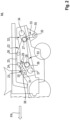
- FIG. 4 is a schematic partial view of a rear region of the combine harvester 1 with a reversing device 54 associated with the chopping device 21 according to the invention.
- the reversing device 54 comprises an output shaft 56 driven by a drive motor, on which an output means is arranged, which is connected to a drive shaft 55 of the chopping device 21 is drivingly connected or connectable to the drive means 57 arranged on the drive shaft 55.
- the reversing device 54 further comprises a frame-like housing 58, which is pivotable about a pivot axis 59 arranged on the combine harvester 1 parallel to the drive shaft 55.
- the drive means 57 is here and preferably designed as a gear.
- the output means of the reversing device 54 is also designed as a gear, corresponding to the drive means 57.
- the drive motor and the output means of the reversing device 54 are arranged in the housing 58.
- the reversing device 54 can be pivoted about the pivot axis 59 by a controllable positioning unit.
- the positioning unit can pivot the reversing device 54 into two end positions, so that the output means of the reversing device 54, designed as a gear, can be brought into or out of engagement with the correspondingly designed drive means 57.
- the output means and the drive means 57 can be temporarily connected to one another in a force-locking and/or form-locking manner.
- the output means and the drive means 57 are permanently engaged with each other, whereby, for example, a switchable freewheel or a switchable clutch on the reversing device prevents forces from being transmitted from them during operation.
- the drive motor can be designed as a hydraulic motor or an electric motor.
- the positioning unit can also be designed as a hydraulic motor or an electric motor.
- both the drive motor and the positioning unit of the reversing device 54 operate according to the same operating principle.
- the combine harvester 1 comprises a control unit 47 configured to control the reversing device 54.
- the control unit 47 can also be configured to control the switchable coupling device that connects the drive machine 4 to the drive system 53.
- drive power is available for other working units of the combine harvester 1 that are to be operated independently of the drive system 53, in particular for a hydraulic circuit of the combine harvester 1.
- at least one hydraulic pump can be operated, which supplies the positioning unit and the drive motor of the reversing device 54 with hydraulic oil.
- the drive machine 4 can, for example, drive a generator that provides the required electrical energy.
- the reversing device 54 thus transmits the rotational speed transmitted from the drive motor to the output means to the drive means 57 on the drive shaft 55 of the chopping device 21. From there, the drive system 53 feeds the rotational speed to the threshing device 8, the torque required for reversing the threshing device 8 being generated by the various transmission ratios within the drive system 53.
Landscapes
- Life Sciences & Earth Sciences (AREA)
- Environmental Sciences (AREA)
- Harvester Elements (AREA)
Claims (12)
- Moissonneuse-batteuse (1) comprenant un dispositif batteur (8) et un dispositif hacheur (21) qui sont entraînés par un système d'entraînement (53), réalisé sous forme de transmissions par courroie (32, 33, 36, 46, 50) et entraîné par une machine d'entraînement (4), et qui sont reliés l'un à l'autre du point de vue de l'entraînement, ainsi qu'un dispositif d'inversion (54) destiné à l'inversion du dispositif de battage (8), caractérisée en ce que le dispositif d'inversion (54) est placé sur un arbre menant (55) du dispositif hacheur (21).
- Moissonneuse-batteuse (1) selon la revendication 1, caractérisée en ce que le dispositif d'inversion (54) comprend un arbre mené (56) qui est entraîné par un moteur d'entraînement et sur lequel est placé un organe mené qui est relié ou peut être relié du point de vue de l'entraînement à un moyen d'entraînement (57) disposé sur l'arbre menant (55) du dispositif hacheur (21).
- Moissonneuse-batteuse (1) selon la revendication 2, caractérisée en ce que l'organe mené et le moyen d'entraînement (57) sont réalisés sous forme de roues dentées.
- Moissonneuse-batteuse (1) selon la revendication 2, caractérisée en ce que l'organe mené et le moyen d'entraînement (57) sont réalisés sous forme de poulies à courroie ou de pignons à chaîne, qui sont reliés entre eux/elles par une courroie d'entraînement ou une chaîne.
- Moissonneuse-batteuse (1) selon une des revendications 2 à 4, caractérisée en ce que le moteur d'entraînement est réalisé sous forme de moteur hydraulique ou de moteur électrique.
- Moissonneuse-batteuse (1) selon une des revendications précédentes, caractérisée en ce que le dispositif d'inversion (54) est monté sur le dispositif hacheur (21) avec possibilité de pivotement autour d'un axe de pivotement (59), aux fins de relier l'organe mené et le moyen d'entraînement (57) entre eux par adhérence et/ou par complémentarité de formes.
- Moissonneuse-batteuse (1) selon la revendication 6, caractérisée en ce que le dispositif d'inversion (54) peut être pivoté autour de l'axe de pivotement (59) par une unité de positionnement pouvant être activée.
- Moissonneuse-batteuse (1) selon une des revendications précédentes, caractérisée en ce que le système d'entraînement (53) présente sur un côté de machine (ML), une première courroie principale (22), entraînée par une poulie d'entraînement principale (24), et une deuxième courroie principale (23), où la première courroie principale (22) entraîne l'arbre d'entraînement (55) du dispositif hacheur (21) par l'intermédiaire d'un premier étage de renvoi (27) et est reliée par la deuxième courroie principale (23) à un arbre passant (35) menant au côté de machine (MR) opposé, sachant que sur le côte de machine (MR) opposé, il est prévu sur l'arbre passant (35) un variateur (42) qui entraîne le dispositif batteur (8).
- Moissonneuse-batteuse (1) selon une des revendications précédentes, caractérisée en ce que, pour l'entraînement d'inversion du dispositif batteur (8), le système d'entraînement (53) peut être désaccouplé de la machine d'entraînement (4).
- Moissonneuse-batteuse (1) selon une des revendications précédentes, caractérisée en ce que la moissonneuse-batteuse (1) comprend une unité de commande (47) qui est conçue pour activer le dispositif d'inversion (54).
- Moissonneuse-batteuse (1) selon la revendication 10, caractérisée en ce que l'unité de commande (47) est conçue pour activer un dispositif d'accouplement commandé qui relie la machine d'entraînement (4) au système d'entraînement (53).
- Moissonneuse-batteuse (1) selon une des revendications précédentes, caractérisée en ce que le dispositif batteur (8) est réalisé sous la forme d'un dispositif à tambours multiples (9, 10, 11).
Applications Claiming Priority (1)
| Application Number | Priority Date | Filing Date | Title |
|---|---|---|---|
| DE102022117780.7A DE102022117780A1 (de) | 2022-07-15 | 2022-07-15 | Mähdrescher |
Publications (2)
| Publication Number | Publication Date |
|---|---|
| EP4305947A1 EP4305947A1 (fr) | 2024-01-17 |
| EP4305947B1 true EP4305947B1 (fr) | 2025-06-11 |
Family
ID=86282654
Family Applications (1)
| Application Number | Title | Priority Date | Filing Date |
|---|---|---|---|
| EP23170567.4A Active EP4305947B1 (fr) | 2022-07-15 | 2023-04-28 | Moissonneuse-batteuse |
Country Status (2)
| Country | Link |
|---|---|
| EP (1) | EP4305947B1 (fr) |
| DE (1) | DE102022117780A1 (fr) |
Families Citing this family (1)
| Publication number | Priority date | Publication date | Assignee | Title |
|---|---|---|---|---|
| US20250151663A1 (en) * | 2023-11-14 | 2025-05-15 | Cnh Industrial Belgium N.V. | Feed roll drive for agricultural harvester thresher |
Family Cites Families (4)
| Publication number | Priority date | Publication date | Assignee | Title |
|---|---|---|---|---|
| DE6913630U (de) | 1969-04-03 | 1969-08-28 | Fahr Ag Maschf | Maehdrescher |
| JPS55128547U (en) * | 1979-02-28 | 1980-09-11 | Kubota Iron Works Co Ltd | Treshing equipment |
| US6247295B1 (en) * | 1999-10-28 | 2001-06-19 | New Holland North America, Inc. | Hydro-mechanical transmission system for an agricultural combine |
| CN103621246B (zh) * | 2013-12-05 | 2017-06-23 | 中联重机股份有限公司 | 一种防缠草的谷物联合收割机 |
-
2022
- 2022-07-15 DE DE102022117780.7A patent/DE102022117780A1/de active Pending
-
2023
- 2023-04-28 EP EP23170567.4A patent/EP4305947B1/fr active Active
Also Published As
| Publication number | Publication date |
|---|---|
| EP4305947A1 (fr) | 2024-01-17 |
| DE102022117780A1 (de) | 2024-01-18 |
Similar Documents
| Publication | Publication Date | Title |
|---|---|---|
| EP1046334B1 (fr) | Dispositif d'entraínement du convoyeur et/ou du dispositif de traitement de récolte | |
| EP2404496B2 (fr) | Cueilleur à maïs | |
| EP2789222B1 (fr) | Système d'entraînement configuré sous forme d'entraînement à courroie d'une moissonneuse-batteuse automotrice | |
| EP1065920A1 (fr) | Dispositif d'alimentation | |
| EP3906770B1 (fr) | Système d'entraînement pour un engin d'abattage-façonnage autonome | |
| EP2687079A2 (fr) | Appareil frontal fonctionnant indépendamment des rangées destiné à récolter des produits de récolte à tiges | |
| DE2246856C3 (fr) | ||
| DE2246856A1 (de) | Antriebsvorrichtung fuer einen selbstfahrenden feldhaecksler | |
| EP4305947B1 (fr) | Moissonneuse-batteuse | |
| DE102009028094B4 (de) | Selbstfahrende Erntemaschine | |
| EP2774473B1 (fr) | Moissonneuse automotrice | |
| EP2132975B1 (fr) | Système d'entraînement pour une moissonneuse | |
| DE102008009447B4 (de) | Selbstfahrende landwirtschaftliche Erntemaschine mit zwei Verbrennungsmotoren | |
| EP1741331B1 (fr) | Faucheuse-hacheuse et procédé de fonctionnement | |
| EP1044598B1 (fr) | Entrainement pour le dispositif de battage de moissonneuses-batteuses | |
| EP1566090B1 (fr) | Machine pour couper des plantes à tige | |
| DE102020205422A1 (de) | Schneckenfördererzusammenbau zur Entladung eines Korntanks eines Mähdreschers | |
| EP1151660B2 (fr) | Récolteuse en particulier faucheuse-hacheuse automotrice | |
| EP4505860B1 (fr) | Cueilleur à maïs et machine agricole équipée avec celui-ci | |
| DE102023132967A1 (de) | Mähdrescher | |
| EP4505859B1 (fr) | Cueilleur à maïs et machine agricole équipée avec celui-ci | |
| EP3906769B1 (fr) | Système d'entraînement pour un engin d'abattage-façonnage autonome | |
| DE102009028055B4 (de) | Selbstfahrende Erntemaschine | |
| DE102013206305B3 (de) | Selbstfahrende landwirtschaftliche Erntemaschine mit zwei Verbrennungsmotoren | |
| DE102024111814A1 (de) | Vorsatzgerät |
Legal Events
| Date | Code | Title | Description |
|---|---|---|---|
| PUAI | Public reference made under article 153(3) epc to a published international application that has entered the european phase |
Free format text: ORIGINAL CODE: 0009012 |
|
| STAA | Information on the status of an ep patent application or granted ep patent |
Free format text: STATUS: THE APPLICATION HAS BEEN PUBLISHED |
|
| AK | Designated contracting states |
Kind code of ref document: A1 Designated state(s): AL AT BE BG CH CY CZ DE DK EE ES FI FR GB GR HR HU IE IS IT LI LT LU LV MC ME MK MT NL NO PL PT RO RS SE SI SK SM TR |
|
| P01 | Opt-out of the competence of the unified patent court (upc) registered |
Effective date: 20240117 |
|
| STAA | Information on the status of an ep patent application or granted ep patent |
Free format text: STATUS: REQUEST FOR EXAMINATION WAS MADE |
|
| 17P | Request for examination filed |
Effective date: 20240717 |
|
| RBV | Designated contracting states (corrected) |
Designated state(s): AL AT BE BG CH CY CZ DE DK EE ES FI FR GB GR HR HU IE IS IT LI LT LU LV MC ME MK MT NL NO PL PT RO RS SE SI SK SM TR |
|
| GRAP | Despatch of communication of intention to grant a patent |
Free format text: ORIGINAL CODE: EPIDOSNIGR1 |
|
| STAA | Information on the status of an ep patent application or granted ep patent |
Free format text: STATUS: GRANT OF PATENT IS INTENDED |
|
| INTG | Intention to grant announced |
Effective date: 20241219 |
|
| GRAS | Grant fee paid |
Free format text: ORIGINAL CODE: EPIDOSNIGR3 |
|
| GRAA | (expected) grant |
Free format text: ORIGINAL CODE: 0009210 |
|
| STAA | Information on the status of an ep patent application or granted ep patent |
Free format text: STATUS: THE PATENT HAS BEEN GRANTED |
|
| AK | Designated contracting states |
Kind code of ref document: B1 Designated state(s): AL AT BE BG CH CY CZ DE DK EE ES FI FR GB GR HR HU IE IS IT LI LT LU LV MC ME MK MT NL NO PL PT RO RS SE SI SK SM TR |
|
| REG | Reference to a national code |
Ref country code: GB Ref legal event code: FG4D Free format text: NOT ENGLISH |
|
| REG | Reference to a national code |
Ref country code: CH Ref legal event code: EP |
|
| REG | Reference to a national code |
Ref country code: DE Ref legal event code: R096 Ref document number: 502023001125 Country of ref document: DE |
|
| REG | Reference to a national code |
Ref country code: IE Ref legal event code: FG4D Free format text: LANGUAGE OF EP DOCUMENT: GERMAN |
|
| PG25 | Lapsed in a contracting state [announced via postgrant information from national office to epo] |
Ref country code: FI Free format text: LAPSE BECAUSE OF FAILURE TO SUBMIT A TRANSLATION OF THE DESCRIPTION OR TO PAY THE FEE WITHIN THE PRESCRIBED TIME-LIMIT Effective date: 20250611 Ref country code: ES Free format text: LAPSE BECAUSE OF FAILURE TO SUBMIT A TRANSLATION OF THE DESCRIPTION OR TO PAY THE FEE WITHIN THE PRESCRIBED TIME-LIMIT Effective date: 20250611 |
|
| REG | Reference to a national code |
Ref country code: LT Ref legal event code: MG9D |
|
| PG25 | Lapsed in a contracting state [announced via postgrant information from national office to epo] |
Ref country code: NO Free format text: LAPSE BECAUSE OF FAILURE TO SUBMIT A TRANSLATION OF THE DESCRIPTION OR TO PAY THE FEE WITHIN THE PRESCRIBED TIME-LIMIT Effective date: 20250911 Ref country code: GR Free format text: LAPSE BECAUSE OF FAILURE TO SUBMIT A TRANSLATION OF THE DESCRIPTION OR TO PAY THE FEE WITHIN THE PRESCRIBED TIME-LIMIT Effective date: 20250912 |
|
| REG | Reference to a national code |
Ref country code: NL Ref legal event code: MP Effective date: 20250611 |
|
| PG25 | Lapsed in a contracting state [announced via postgrant information from national office to epo] |
Ref country code: BG Free format text: LAPSE BECAUSE OF FAILURE TO SUBMIT A TRANSLATION OF THE DESCRIPTION OR TO PAY THE FEE WITHIN THE PRESCRIBED TIME-LIMIT Effective date: 20250611 |
|
| PG25 | Lapsed in a contracting state [announced via postgrant information from national office to epo] |
Ref country code: HR Free format text: LAPSE BECAUSE OF FAILURE TO SUBMIT A TRANSLATION OF THE DESCRIPTION OR TO PAY THE FEE WITHIN THE PRESCRIBED TIME-LIMIT Effective date: 20250611 |
|
| PG25 | Lapsed in a contracting state [announced via postgrant information from national office to epo] |
Ref country code: RS Free format text: LAPSE BECAUSE OF FAILURE TO SUBMIT A TRANSLATION OF THE DESCRIPTION OR TO PAY THE FEE WITHIN THE PRESCRIBED TIME-LIMIT Effective date: 20250911 |
|
| PG25 | Lapsed in a contracting state [announced via postgrant information from national office to epo] |
Ref country code: LV Free format text: LAPSE BECAUSE OF FAILURE TO SUBMIT A TRANSLATION OF THE DESCRIPTION OR TO PAY THE FEE WITHIN THE PRESCRIBED TIME-LIMIT Effective date: 20250611 |
|
| PG25 | Lapsed in a contracting state [announced via postgrant information from national office to epo] |
Ref country code: NL Free format text: LAPSE BECAUSE OF FAILURE TO SUBMIT A TRANSLATION OF THE DESCRIPTION OR TO PAY THE FEE WITHIN THE PRESCRIBED TIME-LIMIT Effective date: 20250611 |
|
| PG25 | Lapsed in a contracting state [announced via postgrant information from national office to epo] |
Ref country code: PT Free format text: LAPSE BECAUSE OF FAILURE TO SUBMIT A TRANSLATION OF THE DESCRIPTION OR TO PAY THE FEE WITHIN THE PRESCRIBED TIME-LIMIT Effective date: 20251013 |
|
| PG25 | Lapsed in a contracting state [announced via postgrant information from national office to epo] |
Ref country code: IS Free format text: LAPSE BECAUSE OF FAILURE TO SUBMIT A TRANSLATION OF THE DESCRIPTION OR TO PAY THE FEE WITHIN THE PRESCRIBED TIME-LIMIT Effective date: 20251011 |
|
| PG25 | Lapsed in a contracting state [announced via postgrant information from national office to epo] |
Ref country code: SM Free format text: LAPSE BECAUSE OF FAILURE TO SUBMIT A TRANSLATION OF THE DESCRIPTION OR TO PAY THE FEE WITHIN THE PRESCRIBED TIME-LIMIT Effective date: 20250611 |
|
| PG25 | Lapsed in a contracting state [announced via postgrant information from national office to epo] |
Ref country code: CZ Free format text: LAPSE BECAUSE OF FAILURE TO SUBMIT A TRANSLATION OF THE DESCRIPTION OR TO PAY THE FEE WITHIN THE PRESCRIBED TIME-LIMIT Effective date: 20250611 |
|
| PG25 | Lapsed in a contracting state [announced via postgrant information from national office to epo] |
Ref country code: PL Free format text: LAPSE BECAUSE OF FAILURE TO SUBMIT A TRANSLATION OF THE DESCRIPTION OR TO PAY THE FEE WITHIN THE PRESCRIBED TIME-LIMIT Effective date: 20250611 |
|
| PG25 | Lapsed in a contracting state [announced via postgrant information from national office to epo] |
Ref country code: EE Free format text: LAPSE BECAUSE OF FAILURE TO SUBMIT A TRANSLATION OF THE DESCRIPTION OR TO PAY THE FEE WITHIN THE PRESCRIBED TIME-LIMIT Effective date: 20250611 |
|
| PG25 | Lapsed in a contracting state [announced via postgrant information from national office to epo] |
Ref country code: SK Free format text: LAPSE BECAUSE OF FAILURE TO SUBMIT A TRANSLATION OF THE DESCRIPTION OR TO PAY THE FEE WITHIN THE PRESCRIBED TIME-LIMIT Effective date: 20250611 |
|
| REG | Reference to a national code |
Ref country code: DE Ref legal event code: R097 Ref document number: 502023001125 Country of ref document: DE |
|
| PG25 | Lapsed in a contracting state [announced via postgrant information from national office to epo] |
Ref country code: DK Free format text: LAPSE BECAUSE OF FAILURE TO SUBMIT A TRANSLATION OF THE DESCRIPTION OR TO PAY THE FEE WITHIN THE PRESCRIBED TIME-LIMIT Effective date: 20250611 |
|
| PG25 | Lapsed in a contracting state [announced via postgrant information from national office to epo] |
Ref country code: IT Free format text: LAPSE BECAUSE OF FAILURE TO SUBMIT A TRANSLATION OF THE DESCRIPTION OR TO PAY THE FEE WITHIN THE PRESCRIBED TIME-LIMIT Effective date: 20250611 |
|
| PLBE | No opposition filed within time limit |
Free format text: ORIGINAL CODE: 0009261 |
|
| STAA | Information on the status of an ep patent application or granted ep patent |
Free format text: STATUS: NO OPPOSITION FILED WITHIN TIME LIMIT |
|
| REG | Reference to a national code |
Ref country code: CH Ref legal event code: L10 Free format text: ST27 STATUS EVENT CODE: U-0-0-L10-L00 (AS PROVIDED BY THE NATIONAL OFFICE) Effective date: 20260423 |