EP1044646B1 - Balai à franges avec manche - Google Patents
Balai à franges avec manche Download PDFInfo
- Publication number
- EP1044646B1 EP1044646B1 EP00104622A EP00104622A EP1044646B1 EP 1044646 B1 EP1044646 B1 EP 1044646B1 EP 00104622 A EP00104622 A EP 00104622A EP 00104622 A EP00104622 A EP 00104622A EP 1044646 B1 EP1044646 B1 EP 1044646B1
- Authority
- EP
- European Patent Office
- Prior art keywords
- handle
- sleeve
- wiper
- mop according
- region
- Prior art date
- Legal status (The legal status is an assumption and is not a legal conclusion. Google has not performed a legal analysis and makes no representation as to the accuracy of the status listed.)
- Expired - Lifetime
Links
Images

Classifications
-
- A—HUMAN NECESSITIES
- A47—FURNITURE; DOMESTIC ARTICLES OR APPLIANCES; COFFEE MILLS; SPICE MILLS; SUCTION CLEANERS IN GENERAL
- A47L—DOMESTIC WASHING OR CLEANING; SUCTION CLEANERS IN GENERAL
- A47L13/00—Implements for cleaning floors, carpets, furniture, walls, or wall coverings
- A47L13/10—Scrubbing; Scouring; Cleaning; Polishing
- A47L13/14—Scrubbing; Scouring; Cleaning; Polishing combined with squeezing or wringing devices
- A47L13/142—Scrubbing; Scouring; Cleaning; Polishing combined with squeezing or wringing devices having torsional squeezing or wringing action
Definitions
- the invention relates to a mop with a handle and a wiper absorbent fringes or the like, which with its lower end on Stem end and with its upper end with one opposite the stalk slidable handle is releasably connected.
- Mops are used more and more, where the wipers can be wrung out by turning the handle mechanically.
- the US PS 1 710 190 shows a mop that has a mechanical Wringing out of the wiper allows.
- the handle of the mop is from a pipe socket that has a handle on which the upper end the wiper is attached.
- the lower end of the wiper is at the end of the handle attached.
- the upper half of the stem is provided with a nut helix and carries another handle.
- the wringing is achieved in that with the one hand holding the pipe socket while holding the other hand one hand holding the pipe socket while holding the other hand the handle on the handle is moved towards the pipe socket and this causes the stem to rotate.
- This mop has the disadvantage that the wiper only reaches the floor with its lower fringes and that the wringing process takes place only by turning the wiper.
- the distance between the wiper ends is always the same, so that when the fringe extend, e.g. if they are wet, no more wringing out can take place; especially since the handle on the handle is only a predetermined one Number of turns can give before the handle on the pipe socket Facility is coming.
- the US PS 2 230 101 describes a mop with a wiper one Double fringing allows. They are for wiping use Fastening parts for the fringe ends directly next to each other and the Fringe loops are double.
- the handle is slidable Provide a handle to which the upper end of the wiper is attached.
- the Handle is equipped with a ball, which is in a groove in the handle is led. This groove has one in the longitudinal direction from the stem end section of the stem, to which a helical second is attached Section joins.
- a rotating knob is attached to the top of the stem, so that the handle when the handle is pulled up and into the engages helical groove, can twist.
- the invention has for its object to create a mop which the wringing process can be accomplished as simply as possible and in which the water is expressed as completely as possible.
- the task is solved with a mop at the beginning mentioned type according to the invention in that the stem in an upper first Part of the area covered by the wiper in the extended, stretched position Area is provided with a Nuthelix in which a guide element of the Handle is guided and an underlying lower second section has, wherein the first portion provided with the nut helix has an enlarged diameter compared to the stem, so that the guide element and thus the handle are released in the second portion.
- the handle is fixed and by the movement of the Handle along the handle, the wiper is stretched, then twisted and finally squeezed. The distance which the handle has to cover the maximum length of the cocked wiper, so twisting of the handle is avoided and the hand holding the handle can Attack the handle near the raised handle.
- the handle is preferably formed from two parts, namely one inner equipped with the guide element and one Fastening device for the upper end of the wiper sleeve and an outer, holding sleeve that can be rotated around the sleeve.
- the Handle thus takes on two functions. For one thing, the sleeve holds it upper end of the wiper and the other must the sleeve when the handle is moved down towards the end of the handle, perform a rotary movement, which is caused by the guide element.
- the sleeve with the Fastening device for the wiper is opposite the holding jacket rotatable.
- a captive, held in the wall of the sleeve, radially displaceable ball can be used.
- the nut helix can be designed as a double helix and two slidable balls can be arranged opposite each other in the sleeve.
- a particularly favorable embodiment is achieved when the Holding jacket is axially displaceable relative to the sleeve and limited by the Displacement locks or releases the guide element. This will ensured that the rotational movement of the upper fastening device for the wiper can be controlled intentionally. This is what happens when you move it of the holding jacket opposite the sleeve up the guide element released while moving the holding jacket down one Locking the guide element results. If the handle of his is moved from the lowest position, the first moves Holding jacket over a limited distance and thereby gives that Guide element free.
- the holding jacket takes the sleeve with it Handle glides over the section with the nut helix without the Guide element is guided in the groove, so that no rotation of the sleeve and so that the fastening device for the wiper takes place.
- the fringe of the Wipers are only pulled out and in the axial direction curious; excited.
- a spring-loaded locking element is attached to the handle, which holds the sleeve in its upper end position. This upper end position of the sleeve can be limited, for example, by an end stop. If the tether is moved down from its upper position, the sleeve remains held from the locking element, initially in its upper end position.
- the sleeve can rotate freely, although the guide element is still locked. This enables one Squeeze the wiper without any further forced rotation. It has been shown in use that this results in a particularly good one Wringing effect is achieved.
- the Fastening device for the upper end of the wiper a larger one Radius as the connection point for the wiper at the end of the handle.
- the fringes then advantageously lie one above the other in the position of use.
- the wiper according to the invention is very easy to use and lets in safe wringing out of the wiper.
- the following mode of operation results.
- the handle In the use position the handle is in its lowest position. The attachment points for the wiper ends are adjacent to each other and the wiper forms freely hanging down Loops. If the handle is pulled up, one finds first Displacement of the holding sheath relative to that covered by the holding sheath Sleeve instead and the guide elements are released. That is called Guide elements can extend radially outwards in the sleeve wall move. By an appropriate design of its holder in the sleeve however, they are prevented from falling outside. Another Movement of the handle upwards, the holding jacket takes the sleeve with and with it also the upper end of the wiper, which by the Fastening device is held on the sleeve.
- the leadership elements are then inside the sleeve wall.
- the handle with jacket and sleeve slides axially over the second section on the stick and then over the first Subarea, which is provided with the Nuthelix, and finally get into their upper end position.
- the sleeve is then locked axially on the stem, but can freely in be rotated in both directions.
- the fringes of the wiper are cocked and aligned approximately parallel to the direction of the handle. If the handle is moved downward, the holding jacket follows first Hand movement and the guide elements are locked in the sleeve, by pushing radially inwards through the inner wall of the holding jacket become.
- the sleeve With a further movement of the handle down the Detachment of the sleeve released, the sleeve taken away and the Guide elements over funnel-shaped groove mouths into the nut helix introduced. Then the guide elements slide in the grooves the sleeve and thus the fastening device and that located upper end of the wiper twisted.
- the rotation follows the predetermined helix groove, which is designed for two to three revolutions. This The number of revolutions is usually sufficient for a tight wrap the fringe to reach the mop handle.
- the possibility of twisting is supported by the fact that the holding device for the upper wiper end moved towards the end of the stem at the same time as the rotation, so that the Distance between the two fastening devices of the wiper ends decreases continuously during the rotation.
- the Nuthelix is in theirs Number of turns, in their length and in their pitch angle, the may vary across the length of the helix, so designed; that in the end the nutelix of the wringing process has largely
- the handle can be moved further down into the lower second section of the mop handle.
- the wiper is then indeed no longer twisted, but it is subject to a further compression, the one allows additional squeezing out of water residues.
- the length of the second section is chosen so that it is approximately the length of the handle equivalent.
- the diameter of this section is less than that Diameter of the area with the nutelix. It is chosen so that it is equal or less of the diameter to the groove base. This ensures that despite the still existing locking of the guide elements, the sleeve is freely rotatable on the mop handle and from the moment from which the leadership elements have left the Nuthelix. After the If the handle is released, the wiper loops are already trying by their weight to return to their original position and the Mop can be used for wiping again.
- the entire process consists of tightening the wiper fringes, turning the Fringes for wringing and pressing the fringes are done by a one-time back and forth movement of the handle.
- the mop 1 shown in Figure 1 has the handle 2 and the wiper 3, the is formed from absorbent fringes.
- the wiper 3 is with its lower one End 4 attached to the stem end 5.
- the upper end 6 of the wiper 3 is on the slidable handle 7 attached.
- the wiper fastenings 3 allow the wiper 3 to be replaced. When the wiper is used 3 the same can therefore be replaced. Used for this Fastening devices are known and therefore not in the drawing shown.
- the wiper 3 is also in Figure 1 on the right side of the Stem 2 only indicated and is the part completely encompassing the stem 2 omitted to avoid the formation of the elements essential to the invention cover.
- the wiper 3 in the illustrated extended position of the Wiper 3 covered area A of stem 2 is in the top first Section B, which is provided with the Nuthelix 8, and the lower second Part C divided.
- section C the stem 2 is left unchanged and has the same diameter as the stem 2 above the the handle 7 raised.
- the guide elements 9 are on the handle 7 attached which when the handle 7 is moved down in the Nuthelix 8 and a twisting and wringing out of the Wiper 3 effect. The rotation continues until the Guide elements 9 step out of the nuthelix 8 and the sub-area C achieved.
- Another movement of the handle 7 causes down a further upsetting of the wiper 3, which is characterized by the previous ones Rotational movements on the handle 2 has created.
- the handle 7 is an inner sleeve 10 on which the Fastening device 12 for the upper end 6 of the wiper 3 and the Guide elements 9 are attached, and the holding jacket 11 is formed.
- the inner diameter of the sleeve 10 is at the outer diameter of the nut helix 8 adjusted so that the sleeve 10 can slide over the nut helix 8.
- the holding jacket 11 is attached, which is rotatable and in the longitudinal direction slidably sits on the sleeve 10.
- guide elements 9 are two themselves in the wall of the sleeve 10 opposite balls inserted.
- the balls 9 are in the wall of the Sleeve 10 captively but displaceable to a limited extent in the radial direction held.
- the nut helix 8 is designed as a double helix, so that each ball 9 has its own groove track.
- the sleeve 10 allows a limited axial displacement of the holding jacket 11, whereby the guide element 9 is released, as shown in the figure, or is locked when the holding jacket 11 with its inner surface Guide element 9 presses inward and locks.
- the movement of the handle 7 upwards is through the end stop 13 limited.
- the end stop 13 is provided with the locking element 14 which the sleeve 10 and thus the handle 7 in its upper end position is held.
- a non-slip covering 15 is also attached to the handle 2 to ensure a good grip for the second hand of the mop user.
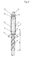
- the handle 7 is shown in FIG.
- the handle 2 is continuous with uniform diameter.
- the Nuthelix 8 is a double helix and on the Stem 2 put on. At this point it should be noted that others Embodiments are possible, e.g. B. that the Nuthelix 8 with the stem 2 as a part are made.
- the handle 7 consists of the sleeve 10, which on her lower end the fastening device 12 for the upper end of the wiper 3 has.
- the sleeve 10 also carries the balls 9, which the Represent guide elements and slide in the grooves of the Nuthelix 8 when the Handle 7 is moved down. Each ball 9 slides in one of them own nut helix.
- the holding jacket 11 is rotatable and axially displaceable on the Mounted sleeve 10. In the figure, the holding jacket 11 is shifted downwards and presses the balls 9 with its inner surface inwards.
- Section B ends at the upper end of the Nuthelix 8. Above the Nuthelix 8 connects to a free area D, which allows the balls 9 to move in the sleeve 10 radially inwards for locking.
- This free area D is in present case formed by the stem 2.
- a flange 16 is attached, which in its Inside is equipped with an annular groove into which the locking element 14 snaps in and thereby holds the sleeve 10 in its upper end position. Moreover the end stop 13 is attached to the handle 2. Moving the holding jacket 11 up leads to the release of the balls 9 and the stop of the Retaining jacket 11 on the flange 16 which finally via the locking element 14 is pushed to the end stop 13.
- the area of the sleeve provided with the balls 9 is enlarged in FIG 10 shown.
- the ball 9 is locked on the left side of the figure and released on the right.
- the holding jacket 11 is on the left side pushed over the ball 9, while on the right side of the holding jacket 11 is withdrawn and releases the ball 9.
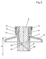
- the Handle 2 as already shown in FIGS. 1 and 2 treated by the nutelix 8 in the Part B bordered.
- the element of the Nuthelix 8 will go up on Stem 2 continued and with a reduced diameter the same or is smaller than the diameter at the bottom of the groove.
- an annular groove 17 are formed which move the balls 9 inwards allows in any position of the sleeve 10.
- At the upper end 18 of the Nuthelix 8 are funnel-shaped mouths 19 provided for easy insertion of the enable locked balls 9 in the groove 20.
Landscapes
- Cleaning Implements For Floors, Carpets, Furniture, Walls, And The Like (AREA)
Claims (10)
- Balai à franges avec manche et un élément d'essuyage formé de franges absorbantes ou éléments similaires qui est relié de manière détachable à l'extrémité du manche par son extrémité inférieure et, par son extrémité supérieure, à une poignée pouvant être déplacée par rapport au manche, caractérisé en ce que le manche (2) est pourvu, dans une première zone partielle supérieure (B) de la zone (A) recouverte par l'élément d'essuyage (3) lorsque celui-ci est en position tendue étirée, d'une gorge hélicoïdale (8) dans laquelle est guidé un élément de guidage (9) de la poignée (7), et comprend une seconde zone partielle inférieure (C) située sous la gorge, la première zone partielle (B) pourvue de la gorge hélicoïdale (8) ayant un diamètre agrandi par rapport au manche (2) de manière à ce que l'élément de guidage (9) et donc, la poignée (7) également, soient libérés dans la seconde zone partielle (C).
- Balai à franges selon la revendication 1, caractérisé en ce que la poignée (7) est formée d'un manchon intérieur (10) pourvu de l'élément de guidage (9) et comprenant un dispositif de fixation (12) pour l'extrémité supérieure (6) de l'élément d'essuyage (3), et d'une enveloppe de maintien extérieure (11) qui entoure le manchon (10) d'une manière permettant une torsion.
- Balai à franges selon la revendication 1 ou 2, caractérisé en ce que l'élément de guidage (9) consiste en au moins une bille maintenue de manière imperdable dans la paroi du manchon (10) et pouvant effectuer un déplacement radial.
- Balai à franges selon l'une des revendications 1 à 3, caractérisé en ce que la gorge hélicoïdale (8) est une double hélice.
- Balai à franges selon l'une des revendications 1 à 4, caractérisé en ce que l'enveloppe de maintien (11) peut effectuer un déplacement axial limité par rapport au manchon (10), verrouillant ainsi ou libérant l'élément de guidage (9).
- Balai à franges selon l'une des revendications 1 à 5, caractérisé en ce que le manche (2) est pourvu, dans sa position finale supérieure, d'un élément d'arrêt (14) monté sur ressort pour le manchon (10).
- Balai à franges selon l'une des revendications 1 à 6, caractérisé en ce que la position finale supérieure du manchon (10) est limitée par une butée de fin de course (13).
- Balai à franges selon l'une des revendications 1 à 7, caractérisé en ce qu'il existe, au-dessus de la zone partielle (B) pourvue de la gorge hélicoïdale (8), une zone libre (D) sous la forme d'une gorge annulaire (17) recevant les éléments de guidage (9) pendant le processus de verrouillage.
- Balai à franges selon l'une des revendications 1 à 8, caractérisé en ce que l'extrémité supérieure (18) de la gorge hélicoïdale (8) possède des embouchures (19) en entonnoir.
- Balai à franges selon l'une des revendications 1 à 9, caractérisé en ce que le dispositif de fixation (12) pour l'extrémité supérieure (6) de l'élément d'essuyage (3), dont est pourvu la poignée (7), a un rayon plus grand que le point d'attache pour l'élément d'essuyage (3) au niveau de l'extrémité (5) du manche.
Applications Claiming Priority (2)
| Application Number | Priority Date | Filing Date | Title |
|---|---|---|---|
| DE19916626A DE19916626C1 (de) | 1999-04-13 | 1999-04-13 | Wischmop mit Stiel |
| DE19916626 | 1999-04-13 |
Publications (3)
| Publication Number | Publication Date |
|---|---|
| EP1044646A2 EP1044646A2 (fr) | 2000-10-18 |
| EP1044646A3 EP1044646A3 (fr) | 2002-03-13 |
| EP1044646B1 true EP1044646B1 (fr) | 2003-08-27 |
Family
ID=7904378
Family Applications (1)
| Application Number | Title | Priority Date | Filing Date |
|---|---|---|---|
| EP00104622A Expired - Lifetime EP1044646B1 (fr) | 1999-04-13 | 2000-03-03 | Balai à franges avec manche |
Country Status (8)
| Country | Link |
|---|---|
| US (1) | US6526617B1 (fr) |
| EP (1) | EP1044646B1 (fr) |
| CN (1) | CN1270003A (fr) |
| AR (1) | AR018481A1 (fr) |
| AT (1) | ATE247924T1 (fr) |
| AU (1) | AU738062B2 (fr) |
| CA (1) | CA2305018C (fr) |
| DE (2) | DE19916626C1 (fr) |
Families Citing this family (10)
| Publication number | Priority date | Publication date | Assignee | Title |
|---|---|---|---|---|
| US20030000036A1 (en) * | 2001-02-16 | 2003-01-02 | Jianhua Fan | Easy mop |
| US20050204495A1 (en) * | 2004-03-18 | 2005-09-22 | Jerzy Perkitny | Motorized mop |
| US7640616B2 (en) * | 2005-11-08 | 2010-01-05 | Brian Wesley Peterson | Mop with integral mop head wringing mechanism |
| TWM294916U (en) * | 2005-12-28 | 2006-08-01 | Jin-Yun Shr | Mop structure |
| AU2006200442B1 (en) * | 2006-02-02 | 2007-04-19 | Hsiao-Hung Chiang | Mop with Drying Mechanism |
| US8011055B2 (en) * | 2006-06-01 | 2011-09-06 | Carl Freudenberg Kg | Cleaning implement |
| USD597271S1 (en) | 2007-03-09 | 2009-07-28 | Carl Freudenberg Kg | Wringer for a cleaning implement |
| ES2340748B1 (es) * | 2007-09-03 | 2011-05-25 | Jesus Angel Oroz Garcia | Mango y cabezal direccional de fregona con mecanismo de ayuda al escurrido. |
| DE202011108402U1 (de) | 2011-11-29 | 2012-01-02 | Silag Handel Ag | Aufnahme für ein Reinigungsgerät |
| USD903211S1 (en) * | 2020-07-23 | 2020-11-24 | Hongtao Gao | Dog pooper scooper rod |
Family Cites Families (11)
| Publication number | Priority date | Publication date | Assignee | Title |
|---|---|---|---|---|
| US1255804A (en) * | 1917-03-31 | 1918-02-05 | Carroline Shipherd | Dish-cleaner and mop. |
| CH110249A (fr) * | 1923-09-12 | 1925-06-01 | Vanderschelden Louis | Appareil de nettoyage. |
| US1710190A (en) * | 1927-11-16 | 1929-04-23 | Parker Regan Corp | Combined mop holder and wringer |
| US2042892A (en) * | 1934-05-25 | 1936-06-02 | Granger Albert | Mop |
| US2230101A (en) * | 1940-04-15 | 1941-01-28 | Edward C Bakemeier | Mop holder and wringer |
| US2365437A (en) * | 1943-06-21 | 1944-12-19 | William G Pankonin | Mop |
| DE4019480C1 (fr) * | 1990-06-19 | 1992-02-06 | Manfred 4790 Paderborn De Klotz | |
| GB2285391B (en) * | 1994-01-11 | 1997-02-05 | Peter Mckay | Improved twist action mop |
| US5722105A (en) * | 1995-12-28 | 1998-03-03 | Thomasson; Stig Ola | Floor mop and wringing mechanism therefor |
| US5907883A (en) * | 1997-02-05 | 1999-06-01 | Thomasson; Stig Ola | Wringing method and wringing mechanism for floor mop |
| US5890253A (en) * | 1997-12-09 | 1999-04-06 | Worldwide Integrated Resources, Inc. | Mop apparatus for unwinding the tangled strands of a mop head |
-
1999
- 1999-04-13 DE DE19916626A patent/DE19916626C1/de not_active Expired - Fee Related
-
2000
- 2000-03-03 EP EP00104622A patent/EP1044646B1/fr not_active Expired - Lifetime
- 2000-03-03 AT AT00104622T patent/ATE247924T1/de not_active IP Right Cessation
- 2000-03-03 DE DE50003411T patent/DE50003411D1/de not_active Expired - Fee Related
- 2000-04-06 CN CN00106420A patent/CN1270003A/zh active Pending
- 2000-04-10 AR ARP000101642A patent/AR018481A1/es unknown
- 2000-04-10 US US09/546,571 patent/US6526617B1/en not_active Expired - Fee Related
- 2000-04-11 AU AU27672/00A patent/AU738062B2/en not_active Ceased
- 2000-04-12 CA CA002305018A patent/CA2305018C/fr not_active Expired - Fee Related
Also Published As
| Publication number | Publication date |
|---|---|
| ATE247924T1 (de) | 2003-09-15 |
| EP1044646A2 (fr) | 2000-10-18 |
| EP1044646A3 (fr) | 2002-03-13 |
| CA2305018C (fr) | 2004-04-06 |
| AR018481A1 (es) | 2001-11-14 |
| CN1270003A (zh) | 2000-10-18 |
| US6526617B1 (en) | 2003-03-04 |
| CA2305018A1 (fr) | 2000-10-13 |
| AU2767200A (en) | 2000-10-19 |
| DE19916626C1 (de) | 2000-07-27 |
| AU738062B2 (en) | 2001-09-06 |
| DE50003411D1 (de) | 2003-10-02 |
Similar Documents
| Publication | Publication Date | Title |
|---|---|---|
| DE60203424T2 (de) | Verlängerungsrohreinrichtung für einen Staubsauger | |
| EP1001867B1 (fr) | Manche pour ustensiles menagers | |
| DE69821022T2 (de) | Auswringverfahren und auswringeinrichtung für fussbodenwischgerät | |
| DE3741900C2 (fr) | ||
| EP1044646B1 (fr) | Balai à franges avec manche | |
| EP4179943B1 (fr) | Machine de nettoyage de sol guidée à la main | |
| DE69815119T2 (de) | Bremseinrichtung | |
| DE2309396C3 (de) | Vorrichtung für Einsatzschraubenschlüssel zur lösbaren axialen Befestigung eines Steckschlüssels | |
| DE4038372A1 (de) | Auswringvorrichtung fuer reinigungselemente von feuchtreinigungsgeraeten | |
| DE212015000108U1 (de) | Drehbarer Moppstiel mit Rollkugeln | |
| EP1180341A2 (fr) | Outil de nettoyage | |
| DE4316590A1 (de) | Drehgelenk für einen ein medizinisches Gerät, eine Leuchte o. dgl. verstellbar aufnehmenden Tragarm | |
| DE202007004390U1 (de) | Auswringbarer Mopp | |
| DE2805615A1 (de) | Mop, insbesondere zur nassreinigung von fussboeden | |
| DE19650867C2 (de) | Feuchtbodenwischgerät | |
| DE2819255C2 (de) | Wäschetrockner | |
| EP1476066A1 (fr) | Balai a franges auto-essorant | |
| CH620354A5 (en) | Washing device | |
| DE202024101020U1 (de) | Ausziehbares Stützbein | |
| DE3309340A1 (de) | Staender fuer einen sonnenschirm | |
| DE102005019624B4 (de) | Feuchtreinigungsgerät | |
| EP1052925B1 (fr) | Appareil de nettoyage des planchers | |
| DE29520612U1 (de) | Wischmop und Auswringteil hierfür | |
| DE19637000C1 (de) | Putzgerät mit Auswringvorrichtung | |
| DE202006015878U1 (de) | Mop |
Legal Events
| Date | Code | Title | Description |
|---|---|---|---|
| PUAI | Public reference made under article 153(3) epc to a published international application that has entered the european phase |
Free format text: ORIGINAL CODE: 0009012 |
|
| AK | Designated contracting states |
Kind code of ref document: A2 Designated state(s): AT BE CH CY DE DK ES FI FR GB GR IE IT LI LU MC NL PT SE |
|
| AX | Request for extension of the european patent |
Free format text: AL;LT;LV;MK;RO;SI |
|
| RAP1 | Party data changed (applicant data changed or rights of an application transferred) |
Owner name: CARL FREUDENBERG KG |
|
| PUAL | Search report despatched |
Free format text: ORIGINAL CODE: 0009013 |
|
| AK | Designated contracting states |
Kind code of ref document: A3 Designated state(s): AT BE CH CY DE DK ES FI FR GB GR IE IT LI LU MC NL PT SE |
|
| AX | Request for extension of the european patent |
Free format text: AL;LT;LV;MK;RO;SI |
|
| 17P | Request for examination filed |
Effective date: 20020215 |
|
| 17Q | First examination report despatched |
Effective date: 20020724 |
|
| AKX | Designation fees paid |
Free format text: AT BE CH CY DE DK ES FI FR GB GR IE IT LI LU MC NL PT SE |
|
| GRAH | Despatch of communication of intention to grant a patent |
Free format text: ORIGINAL CODE: EPIDOS IGRA |
|
| GRAH | Despatch of communication of intention to grant a patent |
Free format text: ORIGINAL CODE: EPIDOS IGRA |
|
| GRAA | (expected) grant |
Free format text: ORIGINAL CODE: 0009210 |
|
| AK | Designated contracting states |
Designated state(s): AT BE CH CY DE DK ES FI FR GB GR IE IT LI LU MC NL PT SE |
|
| PG25 | Lapsed in a contracting state [announced via postgrant information from national office to epo] |
Ref country code: CY Free format text: LAPSE BECAUSE OF FAILURE TO SUBMIT A TRANSLATION OF THE DESCRIPTION OR TO PAY THE FEE WITHIN THE PRESCRIBED TIME-LIMIT Effective date: 20030827 Ref country code: FI Free format text: LAPSE BECAUSE OF FAILURE TO SUBMIT A TRANSLATION OF THE DESCRIPTION OR TO PAY THE FEE WITHIN THE PRESCRIBED TIME-LIMIT Effective date: 20030827 Ref country code: NL Free format text: LAPSE BECAUSE OF FAILURE TO SUBMIT A TRANSLATION OF THE DESCRIPTION OR TO PAY THE FEE WITHIN THE PRESCRIBED TIME-LIMIT Effective date: 20030827 Ref country code: FR Free format text: LAPSE BECAUSE OF FAILURE TO SUBMIT A TRANSLATION OF THE DESCRIPTION OR TO PAY THE FEE WITHIN THE PRESCRIBED TIME-LIMIT Effective date: 20030827 Ref country code: IE Free format text: LAPSE BECAUSE OF FAILURE TO SUBMIT A TRANSLATION OF THE DESCRIPTION OR TO PAY THE FEE WITHIN THE PRESCRIBED TIME-LIMIT Effective date: 20030827 Ref country code: IT Free format text: LAPSE BECAUSE OF FAILURE TO SUBMIT A TRANSLATION OF THE DESCRIPTION OR TO PAY THE FEE WITHIN THE PRESCRIBED TIME-LIMIT;WARNING: LAPSES OF ITALIAN PATENTS WITH EFFECTIVE DATE BEFORE 2007 MAY HAVE OCCURRED AT ANY TIME BEFORE 2007. THE CORRECT EFFECTIVE DATE MAY BE DIFFERENT FROM THE ONE RECORDED. Effective date: 20030827 |
|
| REG | Reference to a national code |
Ref country code: GB Ref legal event code: FG4D Free format text: NOT ENGLISH |
|
| REG | Reference to a national code |
Ref country code: CH Ref legal event code: EP |
|
| REG | Reference to a national code |
Ref country code: IE Ref legal event code: FG4D Free format text: GERMAN |
|
| REF | Corresponds to: |
Ref document number: 50003411 Country of ref document: DE Date of ref document: 20031002 Kind code of ref document: P |
|
| GBT | Gb: translation of ep patent filed (gb section 77(6)(a)/1977) |
Effective date: 20031022 |
|
| PG25 | Lapsed in a contracting state [announced via postgrant information from national office to epo] |
Ref country code: SE Free format text: LAPSE BECAUSE OF FAILURE TO SUBMIT A TRANSLATION OF THE DESCRIPTION OR TO PAY THE FEE WITHIN THE PRESCRIBED TIME-LIMIT Effective date: 20031127 Ref country code: GR Free format text: LAPSE BECAUSE OF FAILURE TO SUBMIT A TRANSLATION OF THE DESCRIPTION OR TO PAY THE FEE WITHIN THE PRESCRIBED TIME-LIMIT Effective date: 20031127 Ref country code: DK Free format text: LAPSE BECAUSE OF FAILURE TO SUBMIT A TRANSLATION OF THE DESCRIPTION OR TO PAY THE FEE WITHIN THE PRESCRIBED TIME-LIMIT Effective date: 20031127 |
|
| PG25 | Lapsed in a contracting state [announced via postgrant information from national office to epo] |
Ref country code: ES Free format text: LAPSE BECAUSE OF FAILURE TO SUBMIT A TRANSLATION OF THE DESCRIPTION OR TO PAY THE FEE WITHIN THE PRESCRIBED TIME-LIMIT Effective date: 20031208 |
|
| PG25 | Lapsed in a contracting state [announced via postgrant information from national office to epo] |
Ref country code: PT Free format text: LAPSE BECAUSE OF FAILURE TO SUBMIT A TRANSLATION OF THE DESCRIPTION OR TO PAY THE FEE WITHIN THE PRESCRIBED TIME-LIMIT Effective date: 20040127 |
|
| NLV1 | Nl: lapsed or annulled due to failure to fulfill the requirements of art. 29p and 29m of the patents act | ||
| PG25 | Lapsed in a contracting state [announced via postgrant information from national office to epo] |
Ref country code: GB Free format text: LAPSE BECAUSE OF NON-PAYMENT OF DUE FEES Effective date: 20040303 Ref country code: AT Free format text: LAPSE BECAUSE OF NON-PAYMENT OF DUE FEES Effective date: 20040303 Ref country code: LU Free format text: LAPSE BECAUSE OF NON-PAYMENT OF DUE FEES Effective date: 20040303 |
|
| PG25 | Lapsed in a contracting state [announced via postgrant information from national office to epo] |
Ref country code: MC Free format text: LAPSE BECAUSE OF NON-PAYMENT OF DUE FEES Effective date: 20040331 Ref country code: CH Free format text: LAPSE BECAUSE OF NON-PAYMENT OF DUE FEES Effective date: 20040331 Ref country code: BE Free format text: LAPSE BECAUSE OF NON-PAYMENT OF DUE FEES Effective date: 20040331 Ref country code: LI Free format text: LAPSE BECAUSE OF NON-PAYMENT OF DUE FEES Effective date: 20040331 |
|
| REG | Reference to a national code |
Ref country code: IE Ref legal event code: FD4D |
|
| PLBE | No opposition filed within time limit |
Free format text: ORIGINAL CODE: 0009261 |
|
| STAA | Information on the status of an ep patent application or granted ep patent |
Free format text: STATUS: NO OPPOSITION FILED WITHIN TIME LIMIT |
|
| 26N | No opposition filed |
Effective date: 20040528 |
|
| EN | Fr: translation not filed | ||
| BERE | Be: lapsed |
Owner name: CARL *FREUDENBERG K.G. Effective date: 20040331 |
|
| PG25 | Lapsed in a contracting state [announced via postgrant information from national office to epo] |
Ref country code: DE Free format text: LAPSE BECAUSE OF NON-PAYMENT OF DUE FEES Effective date: 20041001 |
|
| GBPC | Gb: european patent ceased through non-payment of renewal fee | ||
| REG | Reference to a national code |
Ref country code: CH Ref legal event code: PL |
|
| REG | Reference to a national code |
Ref country code: HK Ref legal event code: WD Ref document number: 1037114 Country of ref document: HK |