EP1044700A2 - Machine d'anesthésie - Google Patents
Machine d'anesthésie Download PDFInfo
- Publication number
- EP1044700A2 EP1044700A2 EP00660068A EP00660068A EP1044700A2 EP 1044700 A2 EP1044700 A2 EP 1044700A2 EP 00660068 A EP00660068 A EP 00660068A EP 00660068 A EP00660068 A EP 00660068A EP 1044700 A2 EP1044700 A2 EP 1044700A2
- Authority
- EP
- European Patent Office
- Prior art keywords
- vaporizer
- flow
- arrangement
- measuring unit
- connecting stud
- Prior art date
- Legal status (The legal status is an assumption and is not a legal conclusion. Google has not performed a legal analysis and makes no representation as to the accuracy of the status listed.)
- Withdrawn
Links
- 206010002091 Anaesthesia Diseases 0.000 title claims abstract description 11
- 230000037005 anaesthesia Effects 0.000 title claims abstract description 11
- 239000006200 vaporizer Substances 0.000 claims abstract description 47
- 230000003444 anaesthetic effect Effects 0.000 claims abstract description 19
- 230000001105 regulatory effect Effects 0.000 claims abstract description 17
- 230000008016 vaporization Effects 0.000 claims abstract description 12
- 238000000034 method Methods 0.000 claims abstract description 10
- 238000009834 vaporization Methods 0.000 claims abstract description 7
- 239000007789 gas Substances 0.000 description 15
- PIWKPBJCKXDKJR-UHFFFAOYSA-N Isoflurane Chemical compound FC(F)OC(Cl)C(F)(F)F PIWKPBJCKXDKJR-UHFFFAOYSA-N 0.000 description 1
- 239000003994 anesthetic gas Substances 0.000 description 1
- 229940035674 anesthetics Drugs 0.000 description 1
- 229960003537 desflurane Drugs 0.000 description 1
- DPYMFVXJLLWWEU-UHFFFAOYSA-N desflurane Chemical compound FC(F)OC(F)C(F)(F)F DPYMFVXJLLWWEU-UHFFFAOYSA-N 0.000 description 1
- 229960000305 enflurane Drugs 0.000 description 1
- JPGQOUSTVILISH-UHFFFAOYSA-N enflurane Chemical compound FC(F)OC(F)(F)C(F)Cl JPGQOUSTVILISH-UHFFFAOYSA-N 0.000 description 1
- 239000003193 general anesthetic agent Substances 0.000 description 1
- 229960003132 halothane Drugs 0.000 description 1
- BCQZXOMGPXTTIC-UHFFFAOYSA-N halothane Chemical compound FC(F)(F)C(Cl)Br BCQZXOMGPXTTIC-UHFFFAOYSA-N 0.000 description 1
- 229960002725 isoflurane Drugs 0.000 description 1
- 239000007788 liquid Substances 0.000 description 1
- 238000012423 maintenance Methods 0.000 description 1
- 238000005259 measurement Methods 0.000 description 1
- 238000012544 monitoring process Methods 0.000 description 1
- 230000003287 optical effect Effects 0.000 description 1
- 238000012545 processing Methods 0.000 description 1
- 229960002078 sevoflurane Drugs 0.000 description 1
- DFEYYRMXOJXZRJ-UHFFFAOYSA-N sevoflurane Chemical compound FCOC(C(F)(F)F)C(F)(F)F DFEYYRMXOJXZRJ-UHFFFAOYSA-N 0.000 description 1
Images
Classifications
-
- A—HUMAN NECESSITIES
- A61—MEDICAL OR VETERINARY SCIENCE; HYGIENE
- A61M—DEVICES FOR INTRODUCING MEDIA INTO, OR ONTO, THE BODY; DEVICES FOR TRANSDUCING BODY MEDIA OR FOR TAKING MEDIA FROM THE BODY; DEVICES FOR PRODUCING OR ENDING SLEEP OR STUPOR
- A61M16/00—Devices for influencing the respiratory system of patients by gas treatment, e.g. ventilators; Tracheal tubes
- A61M16/10—Preparation of respiratory gases or vapours
- A61M16/14—Preparation of respiratory gases or vapours by mixing different fluids, one of them being in a liquid phase
- A61M16/18—Vaporising devices for anaesthetic preparations
- A61M16/186—Locking systems
-
- A—HUMAN NECESSITIES
- A61—MEDICAL OR VETERINARY SCIENCE; HYGIENE
- A61M—DEVICES FOR INTRODUCING MEDIA INTO, OR ONTO, THE BODY; DEVICES FOR TRANSDUCING BODY MEDIA OR FOR TAKING MEDIA FROM THE BODY; DEVICES FOR PRODUCING OR ENDING SLEEP OR STUPOR
- A61M16/00—Devices for influencing the respiratory system of patients by gas treatment, e.g. ventilators; Tracheal tubes
- A61M16/0003—Accessories therefor, e.g. sensors, vibrators, negative pressure
- A61M2016/003—Accessories therefor, e.g. sensors, vibrators, negative pressure with a flowmeter
- A61M2016/0033—Accessories therefor, e.g. sensors, vibrators, negative pressure with a flowmeter electrical
- A61M2016/0039—Accessories therefor, e.g. sensors, vibrators, negative pressure with a flowmeter electrical in the inspiratory circuit
Definitions
- the invention relates to a method in connection with anesthesia equipment, the anesteshesia equipment comprising a gas mixer, a connecting stud having a flow connection with the gas mixer, and a vaporizer, in which method the vaporizer is arranged in the connecting stud for vaporizing an anesthetic and the set value of the vaporizer is set by a mechanical regulator of the vaporizer.
- the invention further relates to an arrangement in connection with anesthesia equipment,
- the invention relates to conventional anesthesia equipment utilising a rack of a particular kind called a Back Bar, onto which various units, such as vaporizers, are attached.
- a Back Bar also enables a flow connection between the different units to be achieved.
- the accuracy of mechanical regulators is directly proportional to a set value.
- the regulator is, for example, provided with a button equipped with an indicator point, which points to a scale.
- solutions of the Back Bar type operate in a completely satisfying manner, but the problem is, for example, that data on gas consumption and set values concerning such conventional vaporizer solutions cannot be advantageously supplied to the data system of for example a hospital, but difficult special procedures, for instance manual data feed or the like, must be employed if the data is to be used in the data system.
- An object of the invention is to provide a method and an arrangement so as to enable disadvantages of the prior art to be eliminated. This is achieved by the invention.
- a method of the invention is characterized by measuring the flow of the vaporizer by a device equipped with a flow measuring unit, by reading the set value of the vaporizer on the basis of the position of a moving regulating member of the mechanical regulator, and by calculating the consumption of the anesthetic on the basis of measured flow data and the set value of vaporization obtained from the moving regulating member of the mechanical regulator.
- An arrangement of the invention is characterized in that a device equipped with a flow measuring unit is arranged to measure the flow of the vaporizer, and that a reference scale corresponding to the regulation scale of the vaporizer is arranged in a moving regulating member of the mechanical regulator, and that the arrangement is equipped with a reader device arranged to read the reference scale, and that the arrangement comprises means for calculating the consumption of the anesthetic on the basis of flow data obtained from the device equipped with the flow measuring unit and the set value of the vaporization obtained from the reader device.
- the main advantage of the invention is that the arrangement can be mounted afterwards in connection with substantially all conventional vaporizers in use, in which case data about gas consumption and settings can be incorporated in a hospital system advantageously.
- the arrangement of the invention also enables new mechanical vaporizers to be rendered electronic-like and thus the same advantages to be achieved in a simple way, as disclosed above in connection with the vaporizers in use at present.
- a further advantage of the arrangement of the invention is that it is simple, which means that the invention is inexpensive to introduce and use. The simplicity of the arrangement of the invention also results in reliable operation and little need for maintenance.
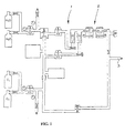
- Figure 1 is a schematic diagrammatic view of a flow arrangement in a conventional anesthesia apparatus.
- a gas mixer is denoted by reference number 1 and a vaporizer arrangement by reference number 2.
- a gas flow supplied to a patient is denoted by reference number 3.
- the flow arrangement according to Figure 1 can be technically implemented in many ways.
- the aforementioned type solution called Back Bar and described in the aforementioned GB 1 385 670 can preferably be used in connection with the gas mixer 1 and a vaporizer.
- the invention thus relates to a vaporizer in an anesthesia apparatus, and to a vaporizer of the Back Bar type in particular.
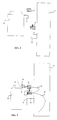
- the invention will be described in closer detail in the accompanying Figures 2 and 3.
- the same reference numbers have the same significance as in Figure 1.
- Figures 1 and 2 schematically show the gas mixer 1 and a vaporizer 2.
- a connecting stud for the vaporizer i.e. a device called Back Bar enabling a flow connection to be established in a manner disclosed in GB 1 385 670, for example, is denoted by reference number 4.
- the vaporizer 2 is equipped with a connecting member 5 compatible with the connecting stud 4.
- the vaporizer 2 is also equipped with means that enable the anesthetic to be fed into the vaporizer. These means are not shown in Figures 2 and 3. The above facts are obvious to one skilled in the art.
- the vaporizer 2 comprises a mechanical regulator comprising a moving regulating member 6, for example a regulating wheel, and by changing the position of the regulating wheel the vaporizing percentage of the vaporizer can be regulated.
- a device 7 equipped with a flow measuring unit is arranged between the vaporizer 2 and the connecting stud 4, and in the example of the figures, the device 7 is arranged to measure the total flow travelling through the vaporizer 2.
- the device can be an appropriately shaped separate fitting piece, as shown in Figures 2 and 3.
- the flow measuring unit can preferably be comprised of means to measure a pressure difference over a laminar flow resistance, in other words a laminar element operating as a flow resistance is used and the pressure difference is measured over this element. Further possible ways include a hot-wire anenometer, flow propeller or measurement based on stagnation pressure.
- a reference scale 8 corresponding to the regulation scale of the vaporizer is arranged in the moving regulating member 6 of the mechanical regulator.
- the reference scale and the regulating scale of the vaporizer are thus similarly divided.
- the reference scale can be, for example, an optically readable scale, electrically readable scale or mechanically readable scale.
- An optically readdable scale can preferably be produced from, for example, a sticker equipped with a bar code and stuck onto the regulating wheel.
- An identifier 12 with e.g. a code 12 to identify the anesthetic used can also be arranged in the reference scale. Hence, the anesthetic being used can preferably be identified.
- the arrangement is further equipped with a reader device 9 arranged to read the reference scale in the moving regulating member 6, to read, for example, the position of the reference scale 8 and the position of the regulation member 6 simultaneously.
- the same reader device also identifies the identifier 12.
- the reader device 9 can be, for example, an optical device or an electrical device, etc. In Figure 3, the reading function of the reader device 9 is schematically shown by an arrow.
- An arrangement of the invention further comprises means for calculating the consumption of anesthetic gas on the basis of the flow data obtained from the device 7 equipped with a flow measuring unit and the set value of the vaporization obtained from the reader device 9.
- the accuracy of the calculation naturally depends on the accuracy of the vaporizer itself, but the accuracy of the calculation is, however, accurate enough for monitoring purposes.
- the means for carrying out the aforementioned calculation can be any conventional means.
- the electronics necessary for data processing and calculating can be preferably arranged in the device 7. The necessary electric power is supplied by a cable or is obtained from a battery. The calculations can be carried out on the basis of the following equations, for example.
- the anesthetic concentration Cmg of mixed gas is defined in the invention on the basis of the position of the regulating member 6 by the reader device 9, and the volume Vmg of mixed gas consumed is measured by the device 7.
- the anesthetic being used can be obtained from the code 12 by means of the reader device 9, and using this information, a correct coefficient Xc can be selected. Coefficient Xc can naturally be obtained otherwise, for example by manually feeding or producing a specific device 7 or calculation electronics only for each anesthetic.
- Gas consumption readings can be transferred, by cable or wirelessly, to a monitor or another device or directly to a data network.
- the cables are schematically shown by reference numbers 10 and 11 in Figure 3. As stated above, the cables can also be used to feed the necessary electric current.
- FIGS 2 and 3 show an arrangement of the invention wherein the device 7 equipped with a flow measuring device is a separate component.
- the flow measuring unit can also be integrated into the connecting stud so as to be a part of the connecting stud 4. In such a case, only one flow measuring element is necessary although the connecting stud 4 might provide places for more, for example for three vaporizers. If the embodiment according to Figures 2 and 3 is used, each vaporizer needs a separate flow measuring unit of its own, in other words each vaporizer should have a device equipped with a flow measuring unit of its own.
Landscapes
- Health & Medical Sciences (AREA)
- Anesthesiology (AREA)
- Heart & Thoracic Surgery (AREA)
- Pulmonology (AREA)
- Engineering & Computer Science (AREA)
- Biomedical Technology (AREA)
- Emergency Medicine (AREA)
- Hematology (AREA)
- Life Sciences & Earth Sciences (AREA)
- Animal Behavior & Ethology (AREA)
- General Health & Medical Sciences (AREA)
- Public Health (AREA)
- Veterinary Medicine (AREA)
- Measuring Volume Flow (AREA)
- Flow Control (AREA)
Applications Claiming Priority (2)
| Application Number | Priority Date | Filing Date | Title |
|---|---|---|---|
| FI990843 | 1999-04-15 | ||
| FI990843A FI106435B (fi) | 1999-04-15 | 1999-04-15 | Menetelmä ja sovitelma anestesialaitteen yhteydessä |
Publications (2)
| Publication Number | Publication Date |
|---|---|
| EP1044700A2 true EP1044700A2 (fr) | 2000-10-18 |
| EP1044700A3 EP1044700A3 (fr) | 2001-09-05 |
Family
ID=8554434
Family Applications (1)
| Application Number | Title | Priority Date | Filing Date |
|---|---|---|---|
| EP00660068A Withdrawn EP1044700A3 (fr) | 1999-04-15 | 2000-04-13 | Machine d'anesthésie |
Country Status (2)
| Country | Link |
|---|---|
| EP (1) | EP1044700A3 (fr) |
| FI (1) | FI106435B (fr) |
Cited By (5)
| Publication number | Priority date | Publication date | Assignee | Title |
|---|---|---|---|---|
| CN102309805A (zh) * | 2010-06-05 | 2012-01-11 | 德尔格医疗有限责任公司 | 带有可取下的麻醉机配量装置的麻醉系统 |
| GB2493085A (en) * | 2011-07-20 | 2013-01-23 | Gen Electric | Anaesthesia system with a valve in a connector |
| US8789524B2 (en) | 2008-01-22 | 2014-07-29 | General Electric Company | Pulse width modulated medical gas concentration control |
| GB2526539A (en) * | 2014-05-23 | 2015-12-02 | Penlon Ltd | Vaporizer |
| CN105457138A (zh) * | 2014-09-10 | 2016-04-06 | 通用电气公司 | 一种用于麻醉机的呼吸回路装置 |
Citations (1)
| Publication number | Priority date | Publication date | Assignee | Title |
|---|---|---|---|---|
| GB1385670A (en) | 1970-11-01 | 1975-02-26 | Cyprane Ltd | Anaesthesia machines |
Family Cites Families (4)
| Publication number | Priority date | Publication date | Assignee | Title |
|---|---|---|---|---|
| DE3813520A1 (de) * | 1988-04-22 | 1989-11-02 | Draegerwerk Ag | Kodierung fuer eine narkoseeinrichtung |
| FI95351C (fi) * | 1990-12-18 | 1996-01-25 | Instrumentarium Oy Datex | Nestettä höyrystävä laite |
| GB9124195D0 (en) * | 1991-11-14 | 1992-01-08 | Boc Group Plc | Connection to a gas cylinder |
| SE505217C2 (sv) * | 1995-10-16 | 1997-07-14 | Gibeck Ab Louis | Anordning för återvinning av anestesimedel |
-
1999
- 1999-04-15 FI FI990843A patent/FI106435B/fi active
-
2000
- 2000-04-13 EP EP00660068A patent/EP1044700A3/fr not_active Withdrawn
Patent Citations (1)
| Publication number | Priority date | Publication date | Assignee | Title |
|---|---|---|---|---|
| GB1385670A (en) | 1970-11-01 | 1975-02-26 | Cyprane Ltd | Anaesthesia machines |
Cited By (10)
| Publication number | Priority date | Publication date | Assignee | Title |
|---|---|---|---|---|
| US8789524B2 (en) | 2008-01-22 | 2014-07-29 | General Electric Company | Pulse width modulated medical gas concentration control |
| CN102309805A (zh) * | 2010-06-05 | 2012-01-11 | 德尔格医疗有限责任公司 | 带有可取下的麻醉机配量装置的麻醉系统 |
| CN102309805B (zh) * | 2010-06-05 | 2014-11-26 | 德尔格医疗有限责任公司 | 带有可取下的麻醉机配量装置的麻醉系统 |
| US9555212B2 (en) | 2010-06-05 | 2017-01-31 | Drägerwerk AG & Co. KGaA | Anesthesia system with detachable anesthetic dispensing device |
| GB2493085A (en) * | 2011-07-20 | 2013-01-23 | Gen Electric | Anaesthesia system with a valve in a connector |
| GB2526539A (en) * | 2014-05-23 | 2015-12-02 | Penlon Ltd | Vaporizer |
| GB2526539B (en) * | 2014-05-23 | 2016-11-02 | Penlon Ltd | Vaporizer |
| US10328230B2 (en) | 2014-05-23 | 2019-06-25 | Penlon Limited | Vaporizer |
| CN105457138A (zh) * | 2014-09-10 | 2016-04-06 | 通用电气公司 | 一种用于麻醉机的呼吸回路装置 |
| CN105457138B (zh) * | 2014-09-10 | 2022-12-13 | 通用电气公司 | 一种用于麻醉机的呼吸回路装置 |
Also Published As
| Publication number | Publication date |
|---|---|
| FI990843A0 (fi) | 1999-04-15 |
| FI990843L (fi) | 2000-10-16 |
| EP1044700A3 (fr) | 2001-09-05 |
| FI106435B (fi) | 2001-02-15 |
Similar Documents
| Publication | Publication Date | Title |
|---|---|---|
| US11679224B2 (en) | Apparatus for measuring properties of gases supplied to a patient | |
| CN114569845B (zh) | 具有多个温度点的热敏电阻器流量传感器 | |
| US6629934B2 (en) | Indirect calorimeter for medical applications | |
| US6945123B1 (en) | Gas flow sensor having redundant flow sensing capability | |
| US10539444B2 (en) | Flow sensor | |
| US12158446B2 (en) | Measuring system for determining gas concentrations | |
| JP2001516015A (ja) | リアルタイムガス解析のための方法及び装置 | |
| EP1707120A2 (fr) | Capteur pour la détermination du quotient d'échange respiratoire | |
| JP2005538819A (ja) | 診断用ガス分析装置及び方法 | |
| US5778874A (en) | Anesthesia machine output monitor | |
| EP1044700A2 (fr) | Machine d'anesthésie | |
| CN113226169A (zh) | 具有动态校准的模块化振量装置 | |
| CN108671344A (zh) | 一种数字氧气质量流量吸入器 | |
| CN201082287Y (zh) | 一种带监测的智能吸氧仪 | |
| US20210379323A1 (en) | Automatic oxygen therapy device | |
| KR20180039904A (ko) | 스마트폰 어플리케이션을 이용한 진단폐활량계와 유발성폐활량계 겸용 폐활량계 | |
| HK40042653B (en) | Apparatus for measuring properties of gases supplied to a patient | |
| HK40042653A (en) | Apparatus for measuring properties of gases supplied to a patient | |
| KR20140035702A (ko) | 물의 전기분해 장치와 수소연료전지를 이용한 간이 폐활량 측정기. | |
| ITBO940039A1 (it) | Dispositivo per la misurazione dei flussi di un fluido in particolare in ventilatori polmonari |
Legal Events
| Date | Code | Title | Description |
|---|---|---|---|
| PUAI | Public reference made under article 153(3) epc to a published international application that has entered the european phase |
Free format text: ORIGINAL CODE: 0009012 |
|
| AK | Designated contracting states |
Kind code of ref document: A2 Designated state(s): AT BE CH CY DE DK ES FI FR GB GR IE IT LI LU MC NL PT SE |
|
| AX | Request for extension of the european patent |
Free format text: AL;LT;LV;MK;RO;SI |
|
| PUAL | Search report despatched |
Free format text: ORIGINAL CODE: 0009013 |
|
| AK | Designated contracting states |
Kind code of ref document: A3 Designated state(s): AT BE CH CY DE DK ES FI FR GB GR IE IT LI LU MC NL PT SE |
|
| AX | Request for extension of the european patent |
Free format text: AL;LT;LV;MK;RO;SI |
|
| RIC1 | Information provided on ipc code assigned before grant |
Free format text: 7A 61M 16/01 A, 7A 61M 16/18 B |
|
| 17P | Request for examination filed |
Effective date: 20020305 |
|
| AKX | Designation fees paid |
Free format text: AT BE CH CY DE DK ES FI FR GB GR IE IT LI LU MC NL PT SE |
|
| AXX | Extension fees paid |
Free format text: AL PAYMENT 20020305;LT PAYMENT 20020305;LV PAYMENT 20020305;MK PAYMENT 20020305;RO PAYMENT 20020305;SI PAYMENT 20020305 |
|
| D17P | Request for examination filed (deleted) | ||
| DAX | Request for extension of the european patent (deleted) | ||
| DBV | Designated contracting states (deleted) | ||
| REG | Reference to a national code |
Ref country code: DE Ref legal event code: 8566 |
|
| STAA | Information on the status of an ep patent application or granted ep patent |
Free format text: STATUS: THE APPLICATION IS DEEMED TO BE WITHDRAWN |
|
| 18D | Application deemed to be withdrawn |
Effective date: 20020306 |