EP1044904A1 - Verfahren und Vorrichtung zum automatischen Abfüllen eines festen Produkts in einen heissen Behälter - Google Patents
Verfahren und Vorrichtung zum automatischen Abfüllen eines festen Produkts in einen heissen Behälter Download PDFInfo
- Publication number
- EP1044904A1 EP1044904A1 EP19990403257 EP99403257A EP1044904A1 EP 1044904 A1 EP1044904 A1 EP 1044904A1 EP 19990403257 EP19990403257 EP 19990403257 EP 99403257 A EP99403257 A EP 99403257A EP 1044904 A1 EP1044904 A1 EP 1044904A1
- Authority
- EP
- European Patent Office
- Prior art keywords
- opening
- automatic filling
- tube
- product
- filling device
- Prior art date
- Legal status (The legal status is an assumption and is not a legal conclusion. Google has not performed a legal analysis and makes no representation as to the accuracy of the status listed.)
- Granted
Links
- 239000012265 solid product Substances 0.000 title claims description 19
- 238000000034 method Methods 0.000 title claims description 10
- 230000008569 process Effects 0.000 title description 3
- 239000003292 glue Substances 0.000 claims abstract description 55
- 238000010438 heat treatment Methods 0.000 claims abstract description 40
- 239000000843 powder Substances 0.000 claims abstract description 4
- 239000000047 product Substances 0.000 claims description 26
- 239000008187 granular material Substances 0.000 claims description 22
- 238000009413 insulation Methods 0.000 claims description 22
- 238000002955 isolation Methods 0.000 claims description 10
- 238000007664 blowing Methods 0.000 claims description 4
- 230000005465 channeling Effects 0.000 claims description 2
- 238000001514 detection method Methods 0.000 claims description 2
- 238000006386 neutralization reaction Methods 0.000 claims description 2
- BASFCYQUMIYNBI-UHFFFAOYSA-N platinum Chemical compound [Pt] BASFCYQUMIYNBI-UHFFFAOYSA-N 0.000 claims 2
- 229910052697 platinum Inorganic materials 0.000 claims 1
- 239000000463 material Substances 0.000 abstract 2
- 239000012943 hotmelt Substances 0.000 description 6
- 229910001220 stainless steel Inorganic materials 0.000 description 4
- 239000010935 stainless steel Substances 0.000 description 4
- 238000000151 deposition Methods 0.000 description 3
- 238000009792 diffusion process Methods 0.000 description 3
- 230000008030 elimination Effects 0.000 description 2
- 238000003379 elimination reaction Methods 0.000 description 2
- 230000007246 mechanism Effects 0.000 description 2
- 238000002844 melting Methods 0.000 description 2
- 230000008018 melting Effects 0.000 description 2
- 239000008188 pellet Substances 0.000 description 2
- 239000000853 adhesive Substances 0.000 description 1
- 230000001070 adhesive effect Effects 0.000 description 1
- 230000004888 barrier function Effects 0.000 description 1
- 230000015572 biosynthetic process Effects 0.000 description 1
- 235000008429 bread Nutrition 0.000 description 1
- 238000001816 cooling Methods 0.000 description 1
- 230000004064 dysfunction Effects 0.000 description 1
- 230000005484 gravity Effects 0.000 description 1
- 239000011810 insulating material Substances 0.000 description 1
- 239000007791 liquid phase Substances 0.000 description 1
- 238000012986 modification Methods 0.000 description 1
- 230000004048 modification Effects 0.000 description 1
- 239000002245 particle Substances 0.000 description 1
- 239000007787 solid Substances 0.000 description 1
- 239000002904 solvent Substances 0.000 description 1
- 238000011144 upstream manufacturing Methods 0.000 description 1
Images


Classifications
-
- B—PERFORMING OPERATIONS; TRANSPORTING
- B65—CONVEYING; PACKING; STORING; HANDLING THIN OR FILAMENTARY MATERIAL
- B65G—TRANSPORT OR STORAGE DEVICES, e.g. CONVEYORS FOR LOADING OR TIPPING, SHOP CONVEYOR SYSTEMS OR PNEUMATIC TUBE CONVEYORS
- B65G53/00—Conveying materials in bulk through troughs, pipes or tubes by floating the materials or by flow of gas, liquid or foam
- B65G53/04—Conveying materials in bulk pneumatically through pipes or tubes; Air slides
- B65G53/06—Gas pressure systems operating without fluidisation of the materials
- B65G53/10—Gas pressure systems operating without fluidisation of the materials with pneumatic injection of the materials by the propelling gas
-
- B—PERFORMING OPERATIONS; TRANSPORTING
- B05—SPRAYING OR ATOMISING IN GENERAL; APPLYING FLUENT MATERIALS TO SURFACES, IN GENERAL
- B05C—APPARATUS FOR APPLYING FLUENT MATERIALS TO SURFACES, IN GENERAL
- B05C11/00—Component parts, details or accessories not specifically provided for in groups B05C1/00 - B05C9/00
- B05C11/10—Storage, supply or control of liquid or other fluent material; Recovery of excess liquid or other fluent material
- B05C11/1042—Storage, supply or control of liquid or other fluent material; Recovery of excess liquid or other fluent material provided with means for heating or cooling the liquid or other fluent material in the supplying means upstream of the applying apparatus
-
- B—PERFORMING OPERATIONS; TRANSPORTING
- B65—CONVEYING; PACKING; STORING; HANDLING THIN OR FILAMENTARY MATERIAL
- B65G—TRANSPORT OR STORAGE DEVICES, e.g. CONVEYORS FOR LOADING OR TIPPING, SHOP CONVEYOR SYSTEMS OR PNEUMATIC TUBE CONVEYORS
- B65G53/00—Conveying materials in bulk through troughs, pipes or tubes by floating the materials or by flow of gas, liquid or foam
- B65G53/04—Conveying materials in bulk pneumatically through pipes or tubes; Air slides
- B65G53/06—Gas pressure systems operating without fluidisation of the materials
- B65G53/10—Gas pressure systems operating without fluidisation of the materials with pneumatic injection of the materials by the propelling gas
- B65G53/14—Gas pressure systems operating without fluidisation of the materials with pneumatic injection of the materials by the propelling gas the gas flow inducing feed of the materials by suction effect
-
- B—PERFORMING OPERATIONS; TRANSPORTING
- B65—CONVEYING; PACKING; STORING; HANDLING THIN OR FILAMENTARY MATERIAL
- B65G—TRANSPORT OR STORAGE DEVICES, e.g. CONVEYORS FOR LOADING OR TIPPING, SHOP CONVEYOR SYSTEMS OR PNEUMATIC TUBE CONVEYORS
- B65G53/00—Conveying materials in bulk through troughs, pipes or tubes by floating the materials or by flow of gas, liquid or foam
- B65G53/34—Details
- B65G53/52—Adaptations of pipes or tubes
- B65G53/526—Adaptations of pipes or tubes with means for special treatment to facilitate transport
-
- B—PERFORMING OPERATIONS; TRANSPORTING
- B65—CONVEYING; PACKING; STORING; HANDLING THIN OR FILAMENTARY MATERIAL
- B65G—TRANSPORT OR STORAGE DEVICES, e.g. CONVEYORS FOR LOADING OR TIPPING, SHOP CONVEYOR SYSTEMS OR PNEUMATIC TUBE CONVEYORS
- B65G53/00—Conveying materials in bulk through troughs, pipes or tubes by floating the materials or by flow of gas, liquid or foam
- B65G53/34—Details
- B65G53/66—Use of indicator or control devices, e.g. for controlling gas pressure, for controlling proportions of material and gas, for indicating or preventing jamming of material
Definitions
- the present invention relates to a device for filling a tank heating with a solid product.
- the present invention relates more particularly to a method and a filling device for a glue tank of a glue depositing machine "Hot Melt”.
- 'Hot Melt' glue It is known machines for depositing glue at high melting temperature, commonly called 'Hot Melt' glue. These machines have a glue tank that is heated between 120 and 200 ° C to maintain the liquid phase glue. 'Hot Melt' glue trays usually have a manually operated cover. Upgrading or refilling these bins require you to manually open the lid and then place a dose of glue in the form of breads or granules. The interior temperature of the bin is very important, this operation is very dangerous and must be repeated frequently in case of intensive use of the generator glue.
- the object of the present invention is therefore to overcome the drawbacks of the prior art by proposing a method of filling a heating tank with a solid product that is simple and effective and whose implementation is without risks for the operator.
- the transfer step is carried out by blowing for a determined time corresponding to the dose of product
- the transfer step is followed by a step signal neutralization for a determined time.
- the thermal insulation zone is obtained by a constant flow of air against the flow of hot product vapor.
- a second object of the invention is to propose a device for filling a heating tank with a solid product that is simple and effective and whose handling is without risk for the operator.
- the filling device automatic heating tank in solid product is characterized in that it includes means for supplying a solid product connected to a means of distribution and means of control making it possible to control the supply means depending on the level of product in the tank, the distribution means, of determined shape, being assembled by its part lower on the heating tray and includes one or more means allowing to create a thermal insulation zone in its upper part.
- the means of supply include a funnel-shaped supply tank connected to a first opening of a T-connector, a tube connected to an air source compressed is connected to a second opening of the T fitting perpendicular to the first, a supply pipe, connected to the third opening of the T-connector, placed opposite the second, establishes the connection with the means of distribution.
- the tube connected to the second opening of the T-connector has a whistle end whose arrangement inside the T-fitting is determined so that the air flow from the tube is channeled mainly in the axis of the third opening towards the supply hose and allows product to be drawn from the tank supply.
- control means control the opening of a solenoid valve inserted between the compressed air source and the T-connector, on reception of a signal emitted by a sensor connected to the means of control and positioned in the heating tray at a determined level of product in the bin.
- control means include a first time delay or dispatch timer which allows keep the solenoid valve open for a corresponding fixed duration to a dose of product transferred to the heating tank.
- control means include a second time delay or product level timer in the tank which allows to hide the signal emitted by the sensor for a period determined when a dose of product has just been transferred.
- a cylinder constituting a reserve air, is interposed between the solenoid valve and the compressed air source in order to provide a strong impulse at the opening of the solenoid valve to allow propel the product present in the T-connector.
- the distribution means consists of a duct of variable shape provided with perforations at its periphery in an area located below the upper end and whose upper end is connected directly or indirectly to the supply pipe, the end lower extending radially outwards by a circular rim to form a base for assembling the conduit opposite a opening of the upper surface of the heating tank, a tube extending to the interior of the duct allows to bring a constant air flow near the the upper end of the conduit to create the insulation area.
- the upper end of the conduit is extended by a fitting, angled or not, connected to the pipe supply, the tube bringing the air flow being integral with this fitting.
- the internal wall of the conduit comprises a deflector for channeling the injected product and optimizing the effectiveness of the insulation zone, and / or the external wall of the duct includes a deflector to optimize the efficiency of the insulation area.
- the distribution means consists of a duct of variable shape, the lower end of which extends radially outwards by a circular rim to form a base allowing to assemble the conduit opposite an opening in the upper surface of the heating tray, and the upper end of which is connected to the fitting, angled or no, connected to the supply pipe, a tube attached to the fitting allows to bring a constant air flow in the fitting, this one having perforations allowing the evacuation of the air diffused by the tube.
- the tube bringing the air flow is extended in the duct or only in the fitting and has holes allowing to diffuse the air throughout the insulation area.
- the conduit consists of a sheet perforated.
- the tube is connected to the air source compressed, a flow limiter is inserted between the source and the tube to check the air flow introduced into the duct.
- the base is assembled on a plate, the opening delimited by the lower end of the conduit being opposite a opening of the plate whose dimensions are greater than the opening of the duct and lower than the opening of the upper surface of the heating tank on which the plate is assembled.
- a third object of the invention is to propose a use of the filling device according to the invention
- the device according to the invention is used to fill a glue tank with a machine for applying glue with glue in the form of granules.
- the device according to the invention comprises a distribution means (6), supply means (5) of the solid product (2) to be introduced into the heating tank (1).
- the solid product is glue and the device described below makes it possible to fill a heating tank or glue tank (2) of a machine for depositing glue.
- the supply means (5) comprise a tank supply (8) that can accommodate the glue (2) in solid form such as granules.
- This tank (8) has the form of a funnel which can be loaded with glue from the top and empty through its lower end (26).
- the end bottom (26) of the supply tank (8) is assembled in a first opening (9) of a T-connector (12), perpendicular to the two other openings (10, 11) of the T-connector.
- the end (16) of a pipe whistle (13), hereinafter called whistle tube (13) is introduced by a second opening (10) of the T-connector (12).
- the whistle tube (13) is connected to a source (14) of compressed air.
- This compressed air supply can be carried out by the company's compressed air network, which is generally 6 bars.
- the air intake is controlled by a solenoid valve (17).
- a carboy (22), of 2.5 liters for example, can be inserted between the solenoid valve (17) and the source of compressed air (14).
- a tube supply (15) is connected to the third opening (11) of the fitting T (12) and the distribution means (6).
- the position of the whistle tube (13) in the T-fitting is determined so that the compressed air flow supplied by the whistle tube does not rise vertically towards the tank supply (8) by the first opening (9) of the T-connector (12), but is mainly channeled in the axis of the third opening (11) in direction of the supply pipe (15).
- the air reserve included in the cylinder (22) provides a very strong impulse when the solenoid valve (17) opens. This strong starting impulse makes it possible to unclog the T-connector (12) filled with glue granules. The glue granules are then sucked from the tank supply by the constant compressed air flow and propelled towards the supply pipe (15).
- the glue tank (1) for example of rectangular shape, comprises four side walls, a bottom and an upper surface (27) provided with a opening (28).
- the glue tank includes heating means (29), consisting, for example, of resistors positioned in the lower part Tray.
- the distribution means (6) comprises a conduit (23) consisting of a truncated cone, the end (28) called upper delimits the smallest opening of the truncated cone and the other end said lower (29) defines the large opening.
- This conduit (23) is called below distribution cone.
- the distribution cone (23) consists of a sheet, stainless steel for example, perforated at least on its upper part.
- the perforations (30) are for example circular.
- the diameter of the perforations is less than dimensions of the glue granules.
- the upper end (28) of the cone distribution (23) is extended by an elbow fitting, for example made of stainless steel, called elbow (31).
- the end (32) of the elbow is connected to the third opening (11) of the T-connector through the supply tube (15).
- the diameter of the elbow (31) stainless steel can correspond substantially to that of the supply pipe (115).
- the lower end (29) or the base of the distribution cone can be extend radially outwards by a circular rim forming a base (33).
- the base (33) of the distribution cone allows the assembly of this on the glue tank (1), facing the opening (28) on the surface upper (27) of the glue tank (1).
- a specific plate (34) each type of glue tank (1) is positioned on the upper surface (27) from the glue tank.
- the plate consists of a parallelepiped plate of a heat insulating material. This plate (34) replaces the cover generally positioned on this type of glue tank (1).
- Two flanges (35), integral with the upper surface of the tank can ensure the assembly of the plate (34) on the glue tank.
- the plate can include a handle positioned on a lateral side to allow safe handling.
- the plate (34) has an opening (36), for example circular, arranged substantially in the center of the plate.
- the base (33) of the cone (23) is positioned on the plate being centered on the opening (36) of the plate (34).
- Two flanges (37), integral with the upper surface (27) of the plate can assemble the cone on the plate. So a means of distribution can be assembled on different types of tray using a plate suitable for each type of bin.
- a tube (39), integral with the elbow, is placed in the cone parallel to the axis (AA ') of the distribution cone.
- This tube is supplied with air and allows to bring a net of air making it possible to create a so-called insulation zone at the top of the cone.
- the interior space of the cone can thus be separated into two parts, an upper part called the isolation zone (4) and a lower part known as the hot zone (38) or Hot Melt.
- the tube has holes of small diameter, in sufficient number to allow diffusion of air in the entire isolation area.
- the cone perforations allow the evacuation of the air diffused by the holes of the tube.
- the tube is extends outside the cone and is connected to the source (14) of compressed air.
- the compressed air supply circuit of the distribution means and the tube in whistle positioned in the T-connector can be closed manually using of the same valve (40).
- the air stream brought by the tube (39) into the cone can be adjusted by a flow limiter (25), inserted between the source (14) and the tube.
- the air stream which can escape through the perforations (30) of the cone, allows ensure a temperature close to the temperature in the insulation zone ambient temperature, around 20 ° C.
- the air net is put in place as soon as it is started means of heating the glue tank and is maintained throughout the duration using the glue tank. It can also be maintained after using the glue tank, until the glue contained in the bac. It creates thermal insulation between the hot zone (38) and the transfer of the granules connecting the tank (8) to the distribution cone.
- the area of thermal insulation forms a barrier to glue vapors from the tank to glue.
- the air stream prevents the glue granules from melting at the isolation zone or upstream, along the transfer path. It thus eliminates all risk of clogging.
- the granules, brought into the cone by blowing, are projected towards the glue tank.
- the shape and dimensions of the cone and the perforations (30) ensure the elimination of air which prevents any bouncing granules or splashes.
- the outer wall of the cone (23) can have a flange (3a) or deflector, arranged perpendicular to the axis (AA ') of the cone (23).
- This deflector allows you to better define the boundary between the area insulation (4) and the hot zone (38) or 'Hot Melt' and improve the efficiency of the isolation area.
- the deflector is positioned inside the cone.
- a deflector (3b) then has the shape of a truncated cone or funnel and is then attached to the inner surface of the cylinder by its end delimiting the largest opening, the small opening of the deflector being oriented towards the opening of the cylinder delimited by its lower end.
- This second type of deflector allows on the one hand to better define the limit between the insulation zone (4) and the hot zone (38) or 'Hot Melt' and improve efficiency of the insulation zone, and on the other hand to channel the glue granules arriving by the elbow.
- the cone can of course include the two types of deflector (3a, 3b).
- Control means (7) make it possible to control the opening and the closing of the solenoid valve (17).
- a sensor (18) is positioned in the tank glue (1) and makes it possible to detect a determined level of glue in the tank.
- This sensor (17) is connected (19) to the control means (7), and emits a signal alarm to the control means (7) for a determined level of adhesive corresponding to the minimum level of glue desired in the tank. So, when the sensor (18) detects a minimum level, the control means control the opening of the solenoid valve (17) in order to transfer by blowing the granules from the supply tank to the glue tank.
- the means of control (7) comprise a first time delay means (20), called shipping delay which keeps the solenoid valve (17) open for a fixed period (T1) corresponding to a fixed dose of granules.
- T1 a fixed period
- the solenoid valve (17) is kept open for a duration (T1) of 3 seconds, corresponding to a dose of granules of 100 to 200 grams.
- the control means (7) can comprise a second means timer (21), called product level timer in the tank, which allows, when a dose of granules has just been transferred, to conceal a possible alarm signal from the sensor (18) for a determined period (T2), to keep the solenoid valve (17) closed.
- This time delay for example of one minute, corresponds approximately to the time necessary for the dose of granules just transferred, to melt properly and distribute homogeneously throughout the tank (1). It thus allows to know if the last propelled dose allows to exceed the minimum level.
- the use of two time delay means as described above makes it possible to fulfill the tank in several times without disturbing the use of the glue tank.
- the device according to the invention makes it possible to position the tank supply (8) away from the glue heating tank, at a distance proportional to the length of the supply tube. The operator can thus loading the tank of pellets without risk. This loading step is the operator's only intervention to allow filling of the heating tray.
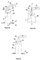
- the cone is replaced by a conduit (41), said to be rounded, the lower end (42) of rectangular or square section of which is perpendicular to the upper end (43) of square section.
- the dimensions of the lower end (43) are greater than those of the upper end (42).
- the rounded duct (41) consists of a perforated sheet or mesh.
- the lower end (42) is extended by a rim forming a base (70). This base makes it possible to assemble the rounded conduit (41) on the surface top of a glue tank.
- the upper end (43) is extended by a fitting consisting of a square section tube, called square tube (44) at the end from which the supply pipe (15) is fixed.
- the inner surface of the rounded duct has a deflector (45) arranged so that it can orient the glue granules supplied by the supply pipe (15) to the lower end (42) of the conduit rounded (41).
- a small tube (46), integral with the square tube (44), makes it possible to create the isolation area (4).
- the air intake tube is arranged inclined inside the square tube, its end (47) being positioned between the deflector and the end upper (43) of the rounded tube.
- the tube has multiple holes allowing to diffuse the air throughout the insulation area.
- the tube extends in outside the square tube and is connected to the compressed air source.
- the shape and dimensions of the rounded duct are defined to allow elimination of efficient air and flow of pellets.
- the rounded tube (41) does not have a deflector but has a non-perforated part (71) disposed opposite the pipe supply (15).
- This non-perforated part (71) extends up to the upper end (43) of the rounded tube.
- a small tube (48) connected to an inlet of air, integral with the square tube, allows to bring an air stream in the square tube (44) but does not enter it.
- the square tube has multiple holes (49) allowing the evacuation of the air supplied by the small tube. Space inside the square tube then constitutes the insulation zone (4).
- the distribution means consists of a cylinder (50) formed of a perforated sheet or roasting.
- the lower end (51) of the cylinder extends outward by a flange forming a base (52).
- the upper end (53) of the cylinder is closed by an upper wall (54).
- the upper wall (54) has a circular opening (55) centered along the axis (BB ') of the cylinder.
- a fitting bent or elbow (56) is fixed by one of its ends on the upper wall (54) of the cylinder, the opening of the elbow delimited by this end being positioned opposite the opening (55) of the wall upper (54).
- the inside diameter of the elbow is substantially equal to that of the opening of the upper wall.
- the elbow is connected by its other end of the supply pipe (15).
- a deflector (57) in the form of truncated cone or funnel is attached to the inner surface of the cylinder by its end defining the largest opening, the small opening of the deflector being oriented towards the opening of the cylinder delimited by its lower end.
- the isolation zone (4) positioned above the deflector is formed by a small tube (58) connected to an air source.
- the small tube can have multiple holes for air diffusion.
- the end of the tube (59) is positioned in the cylinder above the small deflector opening (57).
- the little tube (58) can be integral with the elbow (56) and be arranged parallel to the axis (BB ') of the cylinder.
- the distribution means consists of a cylinder formed (60) of a sheet perforated or wire mesh.
- the lower end (61) of the cylinder extends outwards by a flange forming a base (62).
- the cylinder includes a funnel-shaped upper wall (64) fixed to the upper end (63) of the cylinder by its end defining the largest opening, the small opening being oriented towards the opening of the cylinder delimited by its lower end (61).
- An elbow fitting or cylindrical elbow (65) is attached by one of its ends at the end of the upper wall defining the small opening.
- the other end of the elbow (65) is connected to the pipe supply (15).
- the cylinder is replaced by a conduit (66) consisting of a truncated cone, the end of the conduit delimiting the smallest opening then corresponding to the end top of the cylinder.
- a small pipe (67), integral with the elbow (65), is disposed in the elbow parallel to the axis (CC ') of the conduit (66), as shown in Figure 6b, or substantially perpendicular to the axis (CC ') of the conduit (60), as as shown in Figure 6a.
- the end of the tube can be curved parallel to the axis (CC ') of the duct, so that the air flow is oriented towards the opening of the conduit (60) delimited by its lower end (61).
- the end of the small tube (67, 68) is arranged above of the small opening of the upper wall (64).
- the small tube can have multiple holes for air diffusion.
- the elbow wall comprises, at the periphery of the small tube, multiple perforations (72) allowing the evacuation of the air diffused by the small tube.
- An isolation zone (4) is thus formed above the small opening of the upper wall (64) of the conduit.
- the distribution means such as shown in Figure 6a or 6b, has an additional wall (69) perpendicular to the axis of the cylinder and closing the upper end of the cylinder, the small air intake tube (75) being this time integral with this additional wall.
- Elbow perforations are between the wall additional and the small opening of the deflector.
- the isolation area is then constituted by the space between the additional wall and the wall in funnel shape (64).
- the different means of distribution, described in the second, third and fourth embodiments, can be assembled in the sticks by their base similar to that described for the first mode of realization, using a stage.
- the device according to the invention can be used to fill a container heating with all types of solid products in the form of granules or powder in order to liquefy the product by heating, with the addition of a solvent or no.
Landscapes
- Engineering & Computer Science (AREA)
- Mechanical Engineering (AREA)
- Basic Packing Technique (AREA)
- Supplying Of Containers To The Packaging Station (AREA)
- Container Filling Or Packaging Operations (AREA)
Priority Applications (1)
| Application Number | Priority Date | Filing Date | Title |
|---|---|---|---|
| EP20030290535 EP1350743B1 (de) | 1998-12-29 | 1999-12-23 | Verfahren und Vorrichtung zum automatischen Abfüllen eines festen Produktes in einen heissen Behälter |
Applications Claiming Priority (2)
| Application Number | Priority Date | Filing Date | Title |
|---|---|---|---|
| FR9816781A FR2787770B1 (fr) | 1998-12-29 | 1998-12-29 | Procede et dispositif de remplissage automatique d'un bac chauffant avec un produit solide |
| FR9816781 | 1998-12-29 |
Related Child Applications (1)
| Application Number | Title | Priority Date | Filing Date |
|---|---|---|---|
| EP20030290535 Division EP1350743B1 (de) | 1998-12-29 | 1999-12-23 | Verfahren und Vorrichtung zum automatischen Abfüllen eines festen Produktes in einen heissen Behälter |
Publications (2)
| Publication Number | Publication Date |
|---|---|
| EP1044904A1 true EP1044904A1 (de) | 2000-10-18 |
| EP1044904B1 EP1044904B1 (de) | 2003-10-22 |
Family
ID=9534806
Family Applications (2)
| Application Number | Title | Priority Date | Filing Date |
|---|---|---|---|
| EP19990403257 Expired - Lifetime EP1044904B1 (de) | 1998-12-29 | 1999-12-23 | Verfahren und Vorrichtung zum automatischen Abfüllen eines festen Produkts in einen heissen Behälter |
| EP20030290535 Expired - Lifetime EP1350743B1 (de) | 1998-12-29 | 1999-12-23 | Verfahren und Vorrichtung zum automatischen Abfüllen eines festen Produktes in einen heissen Behälter |
Family Applications After (1)
| Application Number | Title | Priority Date | Filing Date |
|---|---|---|---|
| EP20030290535 Expired - Lifetime EP1350743B1 (de) | 1998-12-29 | 1999-12-23 | Verfahren und Vorrichtung zum automatischen Abfüllen eines festen Produktes in einen heissen Behälter |
Country Status (5)
| Country | Link |
|---|---|
| EP (2) | EP1044904B1 (de) |
| AT (2) | ATE252507T1 (de) |
| DE (2) | DE69931824T2 (de) |
| ES (2) | ES2261887T3 (de) |
| FR (1) | FR2787770B1 (de) |
Cited By (3)
| Publication number | Priority date | Publication date | Assignee | Title |
|---|---|---|---|---|
| US9302857B2 (en) | 2012-04-25 | 2016-04-05 | Nordson Corporation | Pneumatic solids transfer pump |
| US9499355B2 (en) | 2012-10-26 | 2016-11-22 | Nordson Corporation | Pedestal for supporting an adhesive melter and related systems and methods |
| US9580257B2 (en) | 2013-09-04 | 2017-02-28 | Nordson Corporation | Hot melt adhesive supply having agitation device, and related methods |
Families Citing this family (14)
| Publication number | Priority date | Publication date | Assignee | Title |
|---|---|---|---|---|
| FR2885359B1 (fr) * | 2005-05-04 | 2007-06-15 | Df Process Sarl | Raccord coude de depotage pour l'alimentation pneumatique d'un silo de stockage de produit pulverulent |
| ES2283190B1 (es) * | 2005-07-12 | 2008-08-16 | Melton, Sl. | Maquina aplicadora de productos termofusibles. |
| CN101370630B (zh) | 2006-01-17 | 2013-02-06 | 诺信公司 | 用于熔化和分配热塑性材料的装置和方法 |
| US8383991B2 (en) | 2007-10-12 | 2013-02-26 | Nordson Corporation | Adhesive dispensing system with spaced ports and related methods |
| DE102011001276B4 (de) | 2011-03-15 | 2018-05-09 | Symelt Gmbh | Entlüftungsvorrichtung |
| US9169088B2 (en) | 2012-09-20 | 2015-10-27 | Nordson Corporation | Adhesive dispensing device having optimized cyclonic separator unit |
| US9304028B2 (en) | 2012-09-20 | 2016-04-05 | Nordson Corporation | Adhesive dispensing device having optimized reservoir and capacitive level sensor |
| US10099242B2 (en) | 2012-09-20 | 2018-10-16 | Nordson Corporation | Adhesive melter having pump mounted into heated housing |
| US9200741B2 (en) | 2012-10-25 | 2015-12-01 | Nordson Corporation | Adhesive dispensing system and method using smart melt heater control |
| US9120115B2 (en) | 2012-10-25 | 2015-09-01 | Nordson Corporation | Dispensing systems and methods for monitoring actuation signals for diagnostics |
| US9243626B2 (en) | 2012-11-19 | 2016-01-26 | Nordson Corporation | Adhesive dispensing system and method including a pump with integrated diagnostics |
| US9574714B2 (en) | 2013-07-29 | 2017-02-21 | Nordson Corporation | Adhesive melter and method having predictive maintenance for exhaust air filter |
| CN117401448A (zh) * | 2023-11-29 | 2024-01-16 | 河北东泉机械科技有限公司 | 一种防堵塞的气力输灰装置及其方法 |
| WO2026010745A1 (en) * | 2024-07-03 | 2026-01-08 | Henkel Ag & Co. Kgaa | Automatic transfer of solid form adhesive from bulk container |
Citations (3)
| Publication number | Priority date | Publication date | Assignee | Title |
|---|---|---|---|---|
| US4441450A (en) * | 1981-03-12 | 1984-04-10 | Reich Spezialmaschinen Gmbh | Apparatus for melting and applying a meltable adhesive |
| EP0164436A1 (de) * | 1984-06-14 | 1985-12-18 | Wilfried Stein | Vorrichtung für eine dosierte Förderung von staubförmigen Gütern |
| EP0562219A1 (de) * | 1992-03-25 | 1993-09-29 | SIA S.r.l. | Zum Verfahren mit zerstäubtem Harz und System zur Herstellung von Hobelspänenplatten |
Family Cites Families (2)
| Publication number | Priority date | Publication date | Assignee | Title |
|---|---|---|---|---|
| GB1210267A (en) * | 1968-03-19 | 1970-10-28 | Jack Evans Thompson | Improvements in or relating to the control of the flow of heat-fusible substance |
| DE2105037A1 (de) * | 1971-02-03 | 1972-08-17 | Bostik Gmbh, 6370 Oberursel | Verfahren und Vorrichtung zur Abgabe von aus Granulat erschmolzenem Schmelzkleber |
-
1998
- 1998-12-29 FR FR9816781A patent/FR2787770B1/fr not_active Expired - Fee Related
-
1999
- 1999-12-23 DE DE1999631824 patent/DE69931824T2/de not_active Expired - Lifetime
- 1999-12-23 ES ES03290535T patent/ES2261887T3/es not_active Expired - Lifetime
- 1999-12-23 AT AT99403257T patent/ATE252507T1/de not_active IP Right Cessation
- 1999-12-23 EP EP19990403257 patent/EP1044904B1/de not_active Expired - Lifetime
- 1999-12-23 EP EP20030290535 patent/EP1350743B1/de not_active Expired - Lifetime
- 1999-12-23 DE DE1999612240 patent/DE69912240T2/de not_active Expired - Lifetime
- 1999-12-23 ES ES99403257T patent/ES2209364T3/es not_active Expired - Lifetime
- 1999-12-23 AT AT03290535T patent/ATE328826T1/de not_active IP Right Cessation
Patent Citations (3)
| Publication number | Priority date | Publication date | Assignee | Title |
|---|---|---|---|---|
| US4441450A (en) * | 1981-03-12 | 1984-04-10 | Reich Spezialmaschinen Gmbh | Apparatus for melting and applying a meltable adhesive |
| EP0164436A1 (de) * | 1984-06-14 | 1985-12-18 | Wilfried Stein | Vorrichtung für eine dosierte Förderung von staubförmigen Gütern |
| EP0562219A1 (de) * | 1992-03-25 | 1993-09-29 | SIA S.r.l. | Zum Verfahren mit zerstäubtem Harz und System zur Herstellung von Hobelspänenplatten |
Cited By (5)
| Publication number | Priority date | Publication date | Assignee | Title |
|---|---|---|---|---|
| US9302857B2 (en) | 2012-04-25 | 2016-04-05 | Nordson Corporation | Pneumatic solids transfer pump |
| US9555438B2 (en) | 2012-04-25 | 2017-01-31 | Nordson Corporation | Pneumatic solids transfer pump |
| US9499355B2 (en) | 2012-10-26 | 2016-11-22 | Nordson Corporation | Pedestal for supporting an adhesive melter and related systems and methods |
| US10202246B2 (en) | 2012-10-26 | 2019-02-12 | Nordson Corporation | Pedestal for supporting an adhesive melter and related systems and methods |
| US9580257B2 (en) | 2013-09-04 | 2017-02-28 | Nordson Corporation | Hot melt adhesive supply having agitation device, and related methods |
Also Published As
| Publication number | Publication date |
|---|---|
| ATE252507T1 (de) | 2003-11-15 |
| DE69931824D1 (de) | 2006-07-20 |
| FR2787770A1 (fr) | 2000-06-30 |
| EP1350743A1 (de) | 2003-10-08 |
| EP1044904B1 (de) | 2003-10-22 |
| ES2261887T3 (es) | 2006-11-16 |
| DE69931824T2 (de) | 2006-10-12 |
| ATE328826T1 (de) | 2006-06-15 |
| FR2787770B1 (fr) | 2001-02-23 |
| ES2209364T3 (es) | 2004-06-16 |
| DE69912240D1 (de) | 2003-11-27 |
| EP1350743B1 (de) | 2006-06-07 |
| DE69912240T2 (de) | 2004-07-29 |
Similar Documents
| Publication | Publication Date | Title |
|---|---|---|
| EP1044904B1 (de) | Verfahren und Vorrichtung zum automatischen Abfüllen eines festen Produkts in einen heissen Behälter | |
| EP0120171B1 (de) | Vorrichtung zum Reinigen eines Füllkopfes ohne seine Demontage | |
| FR2530485A1 (fr) | Dispositif melangeur et de degazage | |
| WO1989012417A1 (fr) | Dispositif de cuisson automatique pour aliments conditionnes dans une barquette | |
| EP0131480B1 (de) | Strahlverteilvorrichtung für Füllkopf | |
| EP0854334A1 (de) | Behälter zur Aufnahme von Kohlendioxydschnee | |
| WO2000016340A1 (fr) | Procede et installation de remplissage de futs contenant des dechets dangereux | |
| EP1851150B1 (de) | Vorrichtung zur ausgabe von mindestens einem granulatprodukt in einer behälterfüllvorrichtung und verfahren zum füllen einer solchen vorrichtung | |
| EP3890564B1 (de) | Dampfkocherzubehör mit doppelter turbokrone | |
| EP3632574B1 (de) | Pulverbeschichtungssystem | |
| EP3040294B1 (de) | System zur abfall- und sickerwasserlagerung | |
| WO2000065931A1 (fr) | Procede et dispositif de cuisson de batonnets de pomme de terre | |
| FR2663008A1 (fr) | Tremie pour la distribution de produits avec des morceaux. | |
| EP1702871A1 (de) | Flexibler Behälter mit Einbauleitelement | |
| FR2584855A1 (fr) | Conteneur pour dechets radioactifs de moyenne ou faible activite | |
| WO1996015698A1 (fr) | Dispositif de traitement notamment sanitaire d'un matelas de couchage | |
| FR2632284A2 (fr) | Procede pour l'evacuation des poussieres dans les installations de dechargement en vrac | |
| EP4299825A1 (de) | Elektrisches haushaltsgerät zum bügeln und/oder glätten mit einer vorrichtung zum zurückhalten von dampfgetragenen kalkpartikeln | |
| WO2025068661A1 (fr) | Distributeur rechargeable | |
| FR2728245A1 (fr) | Conteneur reutilisable pour produits deshydrates. | |
| FR2575668A1 (fr) | Sas a boules pour evacuer automatiquement les poussieres d'une enceinte en depression | |
| FR3158961A1 (fr) | Equipement de distribution de produit alimentaire liquide ou semi-liquide | |
| EP4267478A1 (de) | Behälter zum transport von flüchtigen pulvern | |
| FR3086557A1 (fr) | Systeme de poudrage | |
| FR2927518A3 (fr) | Systeme de preparation de boisson. |
Legal Events
| Date | Code | Title | Description |
|---|---|---|---|
| PUAI | Public reference made under article 153(3) epc to a published international application that has entered the european phase |
Free format text: ORIGINAL CODE: 0009012 |
|
| AK | Designated contracting states |
Kind code of ref document: A1 Designated state(s): AT BE CH CY DE DK ES FI FR GB GR IE IT LI LU MC NL PT SE |
|
| AX | Request for extension of the european patent |
Free format text: AL;LT;LV;MK;RO;SI |
|
| 17P | Request for examination filed |
Effective date: 20010315 |
|
| AKX | Designation fees paid |
Free format text: AT BE CH CY DE DK ES FI FR GB GR IE IT LI LU MC NL PT SE |
|
| GRAH | Despatch of communication of intention to grant a patent |
Free format text: ORIGINAL CODE: EPIDOS IGRA |
|
| GRAH | Despatch of communication of intention to grant a patent |
Free format text: ORIGINAL CODE: EPIDOS IGRA |
|
| RAP1 | Party data changed (applicant data changed or rights of an application transferred) |
Owner name: NORDSON CORPORATION |
|
| GRAA | (expected) grant |
Free format text: ORIGINAL CODE: 0009210 |
|
| AK | Designated contracting states |
Kind code of ref document: B1 Designated state(s): AT BE CH CY DE DK ES FI FR GB GR IE IT LI LU MC NL PT SE |
|
| PG25 | Lapsed in a contracting state [announced via postgrant information from national office to epo] |
Ref country code: NL Free format text: LAPSE BECAUSE OF FAILURE TO SUBMIT A TRANSLATION OF THE DESCRIPTION OR TO PAY THE FEE WITHIN THE PRESCRIBED TIME-LIMIT Effective date: 20031022 Ref country code: IE Free format text: LAPSE BECAUSE OF FAILURE TO SUBMIT A TRANSLATION OF THE DESCRIPTION OR TO PAY THE FEE WITHIN THE PRESCRIBED TIME-LIMIT Effective date: 20031022 Ref country code: FI Free format text: LAPSE BECAUSE OF FAILURE TO SUBMIT A TRANSLATION OF THE DESCRIPTION OR TO PAY THE FEE WITHIN THE PRESCRIBED TIME-LIMIT Effective date: 20031022 Ref country code: AT Free format text: LAPSE BECAUSE OF FAILURE TO SUBMIT A TRANSLATION OF THE DESCRIPTION OR TO PAY THE FEE WITHIN THE PRESCRIBED TIME-LIMIT Effective date: 20031022 |
|
| REG | Reference to a national code |
Ref country code: GB Ref legal event code: FG4D Free format text: NOT ENGLISH |
|
| REG | Reference to a national code |
Ref country code: CH Ref legal event code: EP |
|
| REG | Reference to a national code |
Ref country code: IE Ref legal event code: FG4D Free format text: FRENCH |
|
| REF | Corresponds to: |
Ref document number: 69912240 Country of ref document: DE Date of ref document: 20031127 Kind code of ref document: P |
|
| PG25 | Lapsed in a contracting state [announced via postgrant information from national office to epo] |
Ref country code: LU Free format text: LAPSE BECAUSE OF NON-PAYMENT OF DUE FEES Effective date: 20031223 Ref country code: CY Free format text: LAPSE BECAUSE OF FAILURE TO SUBMIT A TRANSLATION OF THE DESCRIPTION OR TO PAY THE FEE WITHIN THE PRESCRIBED TIME-LIMIT Effective date: 20031223 |
|
| PG25 | Lapsed in a contracting state [announced via postgrant information from national office to epo] |
Ref country code: MC Free format text: LAPSE BECAUSE OF NON-PAYMENT OF DUE FEES Effective date: 20031231 Ref country code: LI Free format text: LAPSE BECAUSE OF NON-PAYMENT OF DUE FEES Effective date: 20031231 Ref country code: CH Free format text: LAPSE BECAUSE OF NON-PAYMENT OF DUE FEES Effective date: 20031231 Ref country code: BE Free format text: LAPSE BECAUSE OF NON-PAYMENT OF DUE FEES Effective date: 20031231 |
|
| PG25 | Lapsed in a contracting state [announced via postgrant information from national office to epo] |
Ref country code: GR Free format text: LAPSE BECAUSE OF FAILURE TO SUBMIT A TRANSLATION OF THE DESCRIPTION OR TO PAY THE FEE WITHIN THE PRESCRIBED TIME-LIMIT Effective date: 20040122 Ref country code: DK Free format text: LAPSE BECAUSE OF FAILURE TO SUBMIT A TRANSLATION OF THE DESCRIPTION OR TO PAY THE FEE WITHIN THE PRESCRIBED TIME-LIMIT Effective date: 20040122 |
|
| REG | Reference to a national code |
Ref country code: SE Ref legal event code: TRGR |
|
| GBT | Gb: translation of ep patent filed (gb section 77(6)(a)/1977) |
Effective date: 20040204 |
|
| NLV1 | Nl: lapsed or annulled due to failure to fulfill the requirements of art. 29p and 29m of the patents act | ||
| REG | Reference to a national code |
Ref country code: ES Ref legal event code: FG2A Ref document number: 2209364 Country of ref document: ES Kind code of ref document: T3 |
|
| BERE | Be: lapsed |
Owner name: *NORDSON CORP. Effective date: 20031231 |
|
| REG | Reference to a national code |
Ref country code: IE Ref legal event code: FD4D |
|
| REG | Reference to a national code |
Ref country code: CH Ref legal event code: PL |
|
| PLBE | No opposition filed within time limit |
Free format text: ORIGINAL CODE: 0009261 |
|
| STAA | Information on the status of an ep patent application or granted ep patent |
Free format text: STATUS: NO OPPOSITION FILED WITHIN TIME LIMIT |
|
| 26N | No opposition filed |
Effective date: 20040723 |
|
| PG25 | Lapsed in a contracting state [announced via postgrant information from national office to epo] |
Ref country code: PT Free format text: LAPSE BECAUSE OF NON-PAYMENT OF DUE FEES Effective date: 20040322 |
|
| PGFP | Annual fee paid to national office [announced via postgrant information from national office to epo] |
Ref country code: SE Payment date: 20091214 Year of fee payment: 11 |
|
| PGFP | Annual fee paid to national office [announced via postgrant information from national office to epo] |
Ref country code: IT Payment date: 20091222 Year of fee payment: 11 Ref country code: GB Payment date: 20091218 Year of fee payment: 11 |
|
| PGFP | Annual fee paid to national office [announced via postgrant information from national office to epo] |
Ref country code: FR Payment date: 20110104 Year of fee payment: 12 |
|
| PGFP | Annual fee paid to national office [announced via postgrant information from national office to epo] |
Ref country code: DE Payment date: 20101222 Year of fee payment: 12 |
|
| PGFP | Annual fee paid to national office [announced via postgrant information from national office to epo] |
Ref country code: ES Payment date: 20101223 Year of fee payment: 12 |
|
| GBPC | Gb: european patent ceased through non-payment of renewal fee |
Effective date: 20101223 |
|
| REG | Reference to a national code |
Ref country code: SE Ref legal event code: EUG |
|
| PG25 | Lapsed in a contracting state [announced via postgrant information from national office to epo] |
Ref country code: SE Free format text: LAPSE BECAUSE OF NON-PAYMENT OF DUE FEES Effective date: 20101224 |
|
| PG25 | Lapsed in a contracting state [announced via postgrant information from national office to epo] |
Ref country code: GB Free format text: LAPSE BECAUSE OF NON-PAYMENT OF DUE FEES Effective date: 20101223 |
|
| PG25 | Lapsed in a contracting state [announced via postgrant information from national office to epo] |
Ref country code: IT Free format text: LAPSE BECAUSE OF NON-PAYMENT OF DUE FEES Effective date: 20101223 |
|
| REG | Reference to a national code |
Ref country code: FR Ref legal event code: ST Effective date: 20120831 |
|
| REG | Reference to a national code |
Ref country code: DE Ref legal event code: R119 Ref document number: 69912240 Country of ref document: DE Effective date: 20120703 |
|
| PG25 | Lapsed in a contracting state [announced via postgrant information from national office to epo] |
Ref country code: DE Free format text: LAPSE BECAUSE OF NON-PAYMENT OF DUE FEES Effective date: 20120703 |
|
| PG25 | Lapsed in a contracting state [announced via postgrant information from national office to epo] |
Ref country code: FR Free format text: LAPSE BECAUSE OF NON-PAYMENT OF DUE FEES Effective date: 20120102 |
|
| REG | Reference to a national code |
Ref country code: ES Ref legal event code: FD2A Effective date: 20131029 |
|
| PG25 | Lapsed in a contracting state [announced via postgrant information from national office to epo] |
Ref country code: ES Free format text: LAPSE BECAUSE OF NON-PAYMENT OF DUE FEES Effective date: 20111224 |