EP1044916B1 - Cantre à bobines - Google Patents
Cantre à bobines Download PDFInfo
- Publication number
- EP1044916B1 EP1044916B1 EP00105282A EP00105282A EP1044916B1 EP 1044916 B1 EP1044916 B1 EP 1044916B1 EP 00105282 A EP00105282 A EP 00105282A EP 00105282 A EP00105282 A EP 00105282A EP 1044916 B1 EP1044916 B1 EP 1044916B1
- Authority
- EP
- European Patent Office
- Prior art keywords
- strut
- pressure piece
- bobbin creel
- wall
- creel according
- Prior art date
- Legal status (The legal status is an assumption and is not a legal conclusion. Google has not performed a legal analysis and makes no representation as to the accuracy of the status listed.)
- Expired - Lifetime
Links
- 239000000463 material Substances 0.000 claims description 8
- 229920003023 plastic Polymers 0.000 claims description 5
- 239000004033 plastic Substances 0.000 claims description 5
- 238000013459 approach Methods 0.000 description 3
- 230000006835 compression Effects 0.000 description 3
- 238000007906 compression Methods 0.000 description 3
- 238000009940 knitting Methods 0.000 description 3
- 229910052751 metal Inorganic materials 0.000 description 3
- 239000002184 metal Substances 0.000 description 3
- 238000012549 training Methods 0.000 description 3
- 239000011324 bead Substances 0.000 description 2
- 230000015572 biosynthetic process Effects 0.000 description 2
- 238000005553 drilling Methods 0.000 description 2
- 229910000831 Steel Inorganic materials 0.000 description 1
- 229910052782 aluminium Inorganic materials 0.000 description 1
- XAGFODPZIPBFFR-UHFFFAOYSA-N aluminium Chemical compound [Al] XAGFODPZIPBFFR-UHFFFAOYSA-N 0.000 description 1
- 230000004323 axial length Effects 0.000 description 1
- 230000005540 biological transmission Effects 0.000 description 1
- 210000000080 chela (arthropods) Anatomy 0.000 description 1
- 238000002788 crimping Methods 0.000 description 1
- 230000001419 dependent effect Effects 0.000 description 1
- 238000011161 development Methods 0.000 description 1
- 230000018109 developmental process Effects 0.000 description 1
- 230000000694 effects Effects 0.000 description 1
- 230000003993 interaction Effects 0.000 description 1
- 238000004519 manufacturing process Methods 0.000 description 1
- 238000003825 pressing Methods 0.000 description 1
- 238000012545 processing Methods 0.000 description 1
- 238000004080 punching Methods 0.000 description 1
- 238000007789 sealing Methods 0.000 description 1
- 239000007787 solid Substances 0.000 description 1
- 239000010959 steel Substances 0.000 description 1
- 238000012546 transfer Methods 0.000 description 1
Images


Classifications
-
- B—PERFORMING OPERATIONS; TRANSPORTING
- B65—CONVEYING; PACKING; STORING; HANDLING THIN OR FILAMENTARY MATERIAL
- B65H—HANDLING THIN OR FILAMENTARY MATERIAL, e.g. SHEETS, WEBS, CABLES
- B65H49/00—Unwinding or paying-out filamentary material; Supporting, storing or transporting packages from which filamentary material is to be withdrawn or paid-out
- B65H49/02—Methods or apparatus in which packages do not rotate
- B65H49/04—Package-supporting devices
- B65H49/14—Package-supporting devices for several operative packages
- B65H49/16—Stands or frameworks
-
- D—TEXTILES; PAPER
- D04—BRAIDING; LACE-MAKING; KNITTING; TRIMMINGS; NON-WOVEN FABRICS
- D04B—KNITTING
- D04B15/00—Details of, or auxiliary devices incorporated in, weft knitting machines, restricted to machines of this kind
- D04B15/38—Devices for supplying, feeding, or guiding threads to needles
- D04B15/40—Holders or supports for thread packages
- D04B15/42—Frames for assemblies of two or more reels
-
- B—PERFORMING OPERATIONS; TRANSPORTING
- B65—CONVEYING; PACKING; STORING; HANDLING THIN OR FILAMENTARY MATERIAL
- B65H—HANDLING THIN OR FILAMENTARY MATERIAL, e.g. SHEETS, WEBS, CABLES
- B65H2701/00—Handled material; Storage means
- B65H2701/30—Handled filamentary material
- B65H2701/31—Textiles threads or artificial strands of filaments
-
- F—MECHANICAL ENGINEERING; LIGHTING; HEATING; WEAPONS; BLASTING
- F16—ENGINEERING ELEMENTS AND UNITS; GENERAL MEASURES FOR PRODUCING AND MAINTAINING EFFECTIVE FUNCTIONING OF MACHINES OR INSTALLATIONS; THERMAL INSULATION IN GENERAL
- F16B—DEVICES FOR FASTENING OR SECURING CONSTRUCTIONAL ELEMENTS OR MACHINE PARTS TOGETHER, e.g. NAILS, BOLTS, CIRCLIPS, CLAMPS, CLIPS OR WEDGES; JOINTS OR JOINTING
- F16B2200/00—Constructional details of connections not covered for in other groups of this subclass
- F16B2200/40—Clamping arrangements where clamping parts are received in recesses of elements to be connected
- F16B2200/403—Threaded clamping parts
Definitions
- the invention relates to a creel for receiving of bobbins on which thread-like material is wound, with tubular support struts and tubular connection struts, which at connection points by connecting means too are connected to a preferably stable frame, the plug-on holder arranged on support and / or connecting struts for coils.
- Such creels find, for example, as so-called side creels for circular knitting machines extensive application; but they are also for other uses in use where it is concerned arrives threads coming from a variety of bobbins, Wires and the like thread-like material of a common To the processing or treatment center.
- the object of the invention is therefore a creel to create these requirements in the most optimal way Way fulfilled.
- the above is Coil creel according to the invention characterized in that the connecting means into a tubular strut insertable connecting element and a preferably in another outgoing at the respective junction have tubular strut inserted nut, that the connecting element is one for contacting the inner wall the assigned strut pressure piece and has holding means connected thereto, through which the connecting element is releasably fixable in the strut and that in when the connecting element is inserted two struts through one, a through hole in the Wall of a strut crossing and into the threaded nut screwed bolts together are connected, which is supported on the pressure piece.
- the connecting element can be made of plastic material consist. It does not contain any thread or thread like parts that have special requirements Set material strength. It only needs the Tightening the bolt that occurs record and transfer to the inner wall of the strut.
- the pressure member is a substantially cylindrical Has pressure area for contact with the inner wall of the strut.
- the manufacturing accuracy of this Printing area as of the whole pressure piece and Connection element, are not particularly high requirements posed, which to the same extent also for the Shape and diameter tolerance of the inner surface of the tubular Strive applies. For example, you can easily welded pipes are used, like that at all Invention is in no way limited to cylindrical tubes is.
- the tubular struts can be in the form of profile tubes, rectangular or square cross-section, be designed as polygonal profile tubes and the like, to name just a few examples.
- the holding means of the Connecting element can be a form-fitting interaction with the through hole of the strut Have retaining member that as a in the through hole suitable, cone-shaped approach on the Pressure surface of the pressure piece or as a, a projection formed part on the inner wall of the strut can be without being limited to these examples.
- the holding means allow it when inserting the connecting element in the pursuit of this with simple means with regard to the through hole of the respective connection point to fix in the correct position.
- the elastic support means mentioned in one advantageous embodiment an essentially hairpin-shaped Spring part that either integrally to the Pressure piece molded or as a separate part, for example in Shape of a metal spring leaf, connected to it is.
- Another way of training the elastic Support means is, for example, the use of a Compression spring between the pressure piece and the inner wall the strut comes into effect.
- the connecting element as a one-piece Plastic part offers the hairpin-shaped Training of the spring part.
- the pressure piece and the support means expediently one through hole for each Bolt on, the two holes together are aligned.
- the arrangement can be made such that at least the elastic support means a device for placing the support means against the pressure piece pressing tool, for example. Pliers, which in Individual using one described below Embodiment will be explained.
- the through hole can alternatively be a cylindrical hole also as an elongated hole in the or circumferential direction to be so the connection points a certain adjustability of the to allow interconnected struts.
- the described Connecting element also allows striving not to connect the connection points with other struts, but screw it to a wall or something like that in the corresponding threaded nut available is.
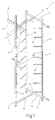
- Coil gate 1 illustrates that of simultaneous Holding a large number of yarn spools 2 is used who are on standby or of those like represented by a bobbin, a thread 3 for one illustrated thread consuming machine, like a Circular knitting machine or the like is withdrawn.
- the creel 1 contains three vertical support struts 4a, 4b, 4c, which are arranged parallel and at a distance from one another are. They are at the corners of an isosceles triangle arranged, at the tip of the support strut 4c located.
- the support struts 4a, 4b, 4c connected by horizontal connecting struts 5, 6, 7 and 8, of which the two connecting struts 5 and 6 the support struts 4a, 4b in the vicinity of their upper or fasten the lower ends together while the two connecting struts 7 and 8, the T-shaped to the Connecting struts 5, 6 run, the support strut 4c the connecting struts 5 and 6.
- All support and connecting struts 4a, 4b, 4c; 5 to 8 are cylindrical in the illustrated embodiment Pipes made of steel or light metal, for example Aluminum are made. They are all the same Inside and outside diameter. These tubes can be seamless drawn, but pipes can also be used that have a welded longitudinal seam.
- the invention is also not limited to creel gates that consist of support and Connection struts constructed in the form of cylindrical tubes are, rather it extends to such Gate, its support and connecting struts made of profiled tubes any cross-section exist, for example rectangular, square or polygonal cross section. There are also no restrictions with regard to the choice of materials. For example, plastic pipes can also be used without further notice Find use.
- creel shown in Figure 1 only one Illustration of the invention chosen simple embodiment of such a creel.
- the invention includes all known forms of creels, such as Round or flat gates, ventilated or unventilated gates etc., as in practice, depending on the particular Purpose, occur.
- connection of the connecting struts 6, 8 and 7, 9 with each other, as well as with the support struts 4a, 4b, 4c happens at connection points 14 in the following 2 to 5 described according to the invention Way, with as an example the junction 14 between the support strut 4a and the connecting strut 5 selected has been.
- the formation of the other connection points 14 is identical.
- connection between the connecting strut 5 and the support strut 4a is made by connecting means that a into the tubular support strut 4a insertable connecting element 15 have, both in Figure 2 as a loose Item as well as in the inserted in the support strut 4a State is illustrated. Parts of these lanyards are also one in the connecting strut 5 inserted threaded nut 16 ( Figure 3) and one in this screw-in threaded bolt 17 with a hexagon socket 18 trained in his head 19 is and a through hole designed as a stepped bore 20 is assigned in the support strut 4a.
- the cylindrical threaded nut 16 has an annular groove 21 trained in the at least one in the wall of the Connecting strut 5 engages bead 22 (FIG. 2), through which the threaded nut 16 in the connecting strut 5 is positively oriented in a stationary manner.
- the connecting element 15 is made in one piece from one Plastic made; alternatively, it can also be from Metal, e.g. die-cast or multi-part from suitable Materials are created. It has a pressure piece 23 on that one of the inner wall of the strut 4 adapted Printing surface 24 bears in the illustrated embodiment essentially partially cylindrical with a on the inner diameter of the tubular support strut 4a is matched cylinder diameter. On the printing surface 24 opposite side is the pressure piece 23 by a substantially flat bearing surface 25 for the Provided screw head 19 of the bolt 17.
- the pressure piece 23 is solid, but can also be ribbed or otherwise in be appropriately structured. In any case, it must but be able to pull the bolt tight Record 17 outgoing pressure forces.
- Holding means are connected to the pressure piece 23, through which the connecting element 15 releasably in the support strut 4a can be fixed. These holding means instruct formed on the pressure piece 23 in the area of its pressure surface 24 Holding member in the form of a cylindrical, cone-shaped Approach 26 on whose outer diameter on the The diameter of the through hole 20 is matched that the pin-shaped extension 26 in the support strut 4a inserted connecting element 15 into the through hole 20 snap into place and thus the connecting element 15 can fix in place.
- the support means an elastic support means connected to the pressure piece 23 on that by a molded, essentially hairpin-shaped spring member 27 is formed, which with a leg on an end face of the pressure piece 23 connects and at the end of his leg with a Ring flange 28 is formed.
- the ring flange 28 is open its upper in Figure 2, the inner wall of the support strut 4a facing outside with a shape of this inner wall adapted, approximately cylindrically curved support surface 29 provided on the inside of the ring flange 28 is assigned an essentially flat contact surface 30 is.
- the axial height of the ring flange 28 is dimensioned such that the connecting element 15 at elastic compressed spring member 27 into the tubular Support strut 4a can be inserted, as shown in Figure 2 is indicated by an arrow 31.
- the bore 36 in the ring flange 28 has one for receiving the screw head 19 suitable larger diameter than that for the shaft of the bolt 17 determined bore 37 in the pressure piece 23.
- the bolt 17 can now be inserted into the through hole 20, and the bores 36, 37 of the connecting element 15 inserted and with the previously in the connecting strut 5 inserted and there by means of the bead 22 or screwed by crimping fixed nut 16 become.
- the connecting strut 5 at 38 (Fig. 2) recessed approximately in a circular shape and thus to the Cylindrical shape of the strut 4a adjusted so that results in a good anti-twist and tilt-proof system.
- the through hole 20 can also as Elongated hole should be formed, the axis of which either in longitudinal strut or circumferential direction.
- the at tightened bolt 17 reached friction Connection between the interconnected struts is usually sufficient for a firm, resilient connection out so that on the by a cylindrical Through hole 20 generated positive locking dispenses can be.
- the screw head 19 arranged by the recessed conditional blind hole-like depression 40 in the wall of the Support strut 4a does not usually interfere; she can but if necessary by a simple, indented one Sealing plugs are closed.
- the pressure piece 23 can also be designed so that in the assembled state of the screw head 19, the through hole 20 essentially in the wall of the support strut 4a closes.
- This embodiment provides additional strength the connection in that the screw head 19 on the wall of the through hole 20 laterally positive is supported.
- This advantage also applies to the cell shown in FIG. 5 further modified embodiment in which the Wall of the support strut 4a on the connection point 14 opposite side too funnel-shaped inside has moved in, as illustrated at 42.
- This embodiment can also be used with the through hole 20 lockable cylindrical extension 26 to be dispensed with because of the provisional fixation of the connecting element 15 in the support strut 4a in the illustrated Way through the annular flange 28a of the connecting element 15 can take place, the conical bore 36a on the diameter of the one to be recorded Projection forming retracted wall part 42 matched is.
- the connecting element 15 in several parts can be trained.
- the spring member 27 in Be shaped like a metallic compression spring, which is connected to the pressure piece 23, as it is at all is conceivable, the spring member 27 by a coil spring or to replace a differently designed spring element that in one piece or as a separate part with the pressure member 23 connected is.
- connection point 14 between a support and a connecting strut explained. It can naturally be used for all types of tubular Parts are used, it is also conceivable such a tubular part that is comparable to the support strut 4a of the embodiment is by means of the screw bolt 17 not on an outgoing strut, but on one fixed part, for example on a wall, with a corresponding Threaded hole is designed to attach.
- the through hole designed as a stepped hole 20 in the support strut 4a is usually by drilling or stamping. This occurs on the inside of the strut a drilling or punching burr that depends on the quality of the tools used more or less is pronounced.
- the bore 36 in the annular flange 28 with a frustoconical chamfer 41 provided in the areas the support surface 29 is formed.
- the connector 15 thus on its two opposite one another Pages with a hole 36 and Hole 37 surrounding depression in the shape of the chamfer 41 or the chamfer 42 is surrounded, it is indifferent from which side of the through hole 20 in the support strut 4a is drilled or punched.
- the recessed chamfer 42 also has the advantage that the force transmission from the pressure surface 24 in the Inner wall of the support strut 4a from the edge of the through hole 20 away, radially outward near the Wall of the connected connecting strut 5 is laid.
- the support of the connecting strut 5 is open the outer wall of the strut 4a still improved. This is particularly important when the screw bolt 17 should be tightened excessively so that the pressure piece 23 in the area of the bore 37 a certain Deflection experienced.
Landscapes
- Engineering & Computer Science (AREA)
- Textile Engineering (AREA)
- Mutual Connection Of Rods And Tubes (AREA)
- Storage Of Web-Like Or Filamentary Materials (AREA)
- Braking Arrangements (AREA)
- Joining Of Building Structures In Genera (AREA)
Claims (13)
- Cantre à bobines (1) destiné à recevoir des bobines sur lesquelles est enroulé un produit (3) sous forme de fil, comportant des montants-supports (4a, 4b, 4c) tubulaires et des traverses de liaison (5-8) tubulaires qui sont liés les uns aux autres par des moyens d'assemblage, en des points d'assemblage (14), pour former un bâti, de préférence stable, qui porte des broches-supports (10) pour les bobines disposées sur les montants-supports et/ou les traverses de liaison, caractérisé en ce que les moyens d'assemblage comprennent un élément d'assemblage (15) à introduire dans un montant-support (4a) tubulaire et un écrou fileté (16), de préférence inséré dans une autre traverse (5) tubulaire, qui s'étend à partir du point d'assemblage (14) considéré, en ce que l'élément d'assemblage (15) comprend une pièce de pression (23) conformée de manière à venir en appui sur la paroi intérieure du montant-support (4a) concerné, ainsi que des moyens de retenue (26, 27, 28) liés à celle-ci, par lesquels l'élément d'assemblage (15) peut être fixé de manière démontable dans le montant-support (4a), et en ce que lorsque l'élément d'assemblage (15) est emmanché, les montant-support et traverse de liaison (4a, 5) concernés sont liés l'un à l'autre par une vis (17) qui est engagée dans un trou traversant (20) dans la paroi du montant-support (4a), est vissée dans l'écrou fileté (16) et prend appui sur la pièce de pression (23).
- Cantre à bobines selon la revendication 1, caractérisé en ce que l'élément d'assemblage (15) est en matière plastique.
- Cantre à bobines selon la revendication 1 ou 2, caractérisé en ce que la pièce de pression (23) présente une surface de pression (24) essentiellement adaptée à la paroi intérieure du montant-support, destinée à venir en appui sur la paroi intérieure du montant-support (4a).
- Cantre à bobines selon une des revendications précédentes, caractérisé en ce que les moyens de retenue présentent un organe de retenue (26) adapté pour coopérer par complémentarité de formes avec le trou traversant (20) du montant-support (4a).
- Cantre à bobines selon la revendication 4, caractérisé en ce que l'organe de retenue (26) est un bossage (26) en forme de téton sur la surface de pression (24) de la pièce de pression (23), qui s'engage dans le trou traversant (20).
- Cantre à bobines selon la revendication 4, caractérisé en ce que l'organe de retenue est conformé en élément (28a) pourvu d'une saillie (42) sur la paroi intérieure du montant-support (4a).
- Cantre à bobines selon une des revendications précédentes, caractérisé en ce que les moyens de retenue présentent un moyen de poussée élastique qui est lié à la pièce de pression (23) et par lequel ladite pièce de pression (23) peut être pressée contre la paroi du montant-support (4a).
- Cantre à bobines selon la revendication 7, caractérisé en ce que le moyen de poussée élastique comprend un élément formant ressort (27), essentiellement en forme d'épingle à cheveux, qui soit est réalisé d'un bloc avec la pièce de pression (23), soit est lié à celle-ci en tant qu'élément distinct.
- Cantre à bobines selon la revendication 7 ou 8, caractérisé en ce que la pièce de pression (23) et le moyen de poussée présentent chacun un trou traversant (37, 36) pour la vis (17) et en ce que le trou (36) dans le moyen de poussée est agencé pour recevoir au moins partiellement la tête (19) de la vis (17).
- Cantre à bobines selon une des revendications 7 à 9, caractérisé en ce qu'au moins le moyen de poussée élastique comprend un dispositif (33) pour la mise en place d'un outil qui repousse le moyen de pression en direction de la pièce de pression (23).
- Cantre à bobines selon la revendication 10, caractérisé en ce que le dispositif présente un prolongement (33) et une surface d'action d'outil (35) associée à celui-ci, éventuellement en creux, aménagés sur le moyen de poussée (27, 28) élastique et la pièce de pression (23).
- Cantre à bobines selon une des revendications précédentes, caractérisé en ce que la pièce de pression (23) présente une surface d'appui (25) pour l'appui axial de la vis (17), dont la distance par rapport à la surface de pression (24) en vis-à-vis est telle que la vis (17) à l'état serré soit essentiellement logée dans le trou traversant (20) et ferme essentiellement celui-ci côté surface extérieure du montant-support.
- Cantre à bobines selon une des revendications précédentes, caractérisé en ce que le trou traversant (20) est conformé en trou oblong.
Applications Claiming Priority (2)
| Application Number | Priority Date | Filing Date | Title |
|---|---|---|---|
| DE19916483 | 1999-04-13 | ||
| DE19916483A DE19916483C1 (de) | 1999-04-13 | 1999-04-13 | Spulengatter |
Publications (3)
| Publication Number | Publication Date |
|---|---|
| EP1044916A2 EP1044916A2 (fr) | 2000-10-18 |
| EP1044916A3 EP1044916A3 (fr) | 2001-08-29 |
| EP1044916B1 true EP1044916B1 (fr) | 2003-07-30 |
Family
ID=7904292
Family Applications (1)
| Application Number | Title | Priority Date | Filing Date |
|---|---|---|---|
| EP00105282A Expired - Lifetime EP1044916B1 (fr) | 1999-04-13 | 2000-03-14 | Cantre à bobines |
Country Status (8)
| Country | Link |
|---|---|
| US (1) | US6345783B1 (fr) |
| EP (1) | EP1044916B1 (fr) |
| CN (1) | CN100335389C (fr) |
| DE (2) | DE19916483C1 (fr) |
| ES (1) | ES2199105T3 (fr) |
| PT (1) | PT1044916E (fr) |
| TR (1) | TR200000981A2 (fr) |
| TW (1) | TW506422U (fr) |
Cited By (2)
| Publication number | Priority date | Publication date | Assignee | Title |
|---|---|---|---|---|
| DE102008029448B3 (de) * | 2008-06-20 | 2010-02-11 | Memminger-Iro Gmbh | Spulengatter |
| DE102009022455A1 (de) | 2009-05-23 | 2010-12-09 | Memminger-Iro Gmbh | Befestigungsklemme für Spulengatter |
Families Citing this family (14)
| Publication number | Priority date | Publication date | Assignee | Title |
|---|---|---|---|---|
| DE102005015415A1 (de) * | 2005-04-04 | 2006-10-05 | Bilsing Automation Gmbh | Befestigungsanordnung zur Verbindung von sich kreuzenden oder T-förmigen aneinandergrenzenden Rohren und Rohrrahmen mit derart verbundenen Rohren |
| US20090067971A1 (en) * | 2007-01-19 | 2009-03-12 | David Chadwick | Package manipulator |
| DE102010005248B4 (de) * | 2010-01-20 | 2014-07-10 | Alfred Plachetta | Vorrichtung zur Montage eines rohrförmigen Bauteils |
| US9132987B2 (en) | 2011-11-04 | 2015-09-15 | The Procter & Gamble Plaza | Apparatus with rotatable arm for unwinding strands of material |
| US9051151B2 (en) | 2011-11-04 | 2015-06-09 | The Procter & Gamble Company | Splicing apparatus for unwinding strands of material |
| CA2859964A1 (fr) * | 2011-12-22 | 2013-06-27 | The Procter & Gamble Company | Machine compacte pour le deroulement de multiples brins de materiau |
| CN103008739B (zh) * | 2012-11-30 | 2015-05-13 | 东台耀强机械制造有限公司 | 焊缝相贯线坡口切削加工设备 |
| CN103114375B (zh) * | 2013-03-18 | 2014-06-25 | 慈溪太阳洲纺织科技有限公司 | 针织机纱架结构 |
| US20160278520A1 (en) * | 2015-03-27 | 2016-09-29 | Ludwig Dawson | Funnel Support and Storage Systems |
| CN108843253A (zh) * | 2018-08-01 | 2018-11-20 | 西南石油大学 | 一种井下复合举升抽油机油管与储油管连接接头 |
| CN109733943A (zh) * | 2018-10-30 | 2019-05-10 | 德清县德盛纺织品有限公司 | 丝线筒取放架 |
| CN109230816B (zh) * | 2018-10-31 | 2024-02-27 | 德清县德盛纺织品有限公司 | 多功能悬挂架 |
| US12522466B2 (en) * | 2022-03-24 | 2026-01-13 | Belmont Textile Machinery Company | Powered creel systems, receiver apparatuses and related methods for yarn packages |
| USD1110780S1 (en) * | 2023-07-05 | 2026-02-03 | EP Family Corp. | Storage rack |
Family Cites Families (14)
| Publication number | Priority date | Publication date | Assignee | Title |
|---|---|---|---|---|
| US932522A (en) * | 1905-06-23 | 1909-08-31 | Simon W Wardwell | Creel. |
| USRE17441E (en) * | 1925-08-26 | 1929-09-24 | Joint | |
| US2108398A (en) * | 1936-08-13 | 1938-02-15 | United American Bosch Corp | Mounting for tubular articles |
| US3884588A (en) * | 1971-04-08 | 1975-05-20 | Metafab Ind Inc | Tube joining system |
| IT986496B (it) * | 1972-06-20 | 1975-01-30 | We Booton Ltd | Rastrelliera per bobine di filato per macchine di maglieria |
| DE7338340U (de) * | 1972-11-07 | 1974-01-31 | Dubied E & Cie Sa | Spulengatter für eine Rundstrickmaschine |
| US3867048A (en) * | 1973-02-20 | 1975-02-18 | Abraham Endzweig | Plug connections for vertically abutting frame sections |
| DE7925578U1 (de) * | 1979-09-10 | 1980-10-02 | Sipra Patententwicklungs- Und Beteiligungsgesellschaft Mbh, 7000 Stuttgart | Spulenstaender fuer spulengatter von rundstrickmaschinen |
| US4386870A (en) * | 1980-11-19 | 1983-06-07 | Baroody Terrance A | Structural tee joint |
| DE8428056U1 (de) * | 1984-09-24 | 1985-05-30 | Barth, Peter, 7455 Jungingen | Rohrklemmverbindung fuer textilspulengatter |
| US5230581A (en) * | 1992-06-03 | 1993-07-27 | Deng Ming Hui | Coupling apparatus for a T-shaped tube unit |
| CA2191904C (fr) * | 1996-12-03 | 2000-02-15 | Lausan Chung Hsin Liu | Raccord de tiges pour chaise pliante |
| DE29819815U1 (de) * | 1998-11-05 | 1999-01-07 | Lin, Tean-Lai, Taipeh/T'ai-pei | Fadengestell für eine Strickmaschine |
| US6227752B1 (en) * | 1999-11-16 | 2001-05-08 | Da International, Ltd. | Failsafe weld-free method of joining tubular elements |
-
1999
- 1999-04-13 DE DE19916483A patent/DE19916483C1/de not_active Expired - Fee Related
-
2000
- 2000-03-14 DE DE50003059T patent/DE50003059D1/de not_active Expired - Fee Related
- 2000-03-14 PT PT00105282T patent/PT1044916E/pt unknown
- 2000-03-14 ES ES00105282T patent/ES2199105T3/es not_active Expired - Lifetime
- 2000-03-14 EP EP00105282A patent/EP1044916B1/fr not_active Expired - Lifetime
- 2000-04-07 TW TW090217365U patent/TW506422U/zh not_active IP Right Cessation
- 2000-04-12 TR TR2000/00981A patent/TR200000981A2/xx unknown
- 2000-04-13 CN CNB001067052A patent/CN100335389C/zh not_active Expired - Fee Related
- 2000-04-13 US US09/548,713 patent/US6345783B1/en not_active Expired - Fee Related
Cited By (3)
| Publication number | Priority date | Publication date | Assignee | Title |
|---|---|---|---|---|
| DE102008029448B3 (de) * | 2008-06-20 | 2010-02-11 | Memminger-Iro Gmbh | Spulengatter |
| DE102009022455A1 (de) | 2009-05-23 | 2010-12-09 | Memminger-Iro Gmbh | Befestigungsklemme für Spulengatter |
| DE102009022455B4 (de) * | 2009-05-23 | 2012-12-06 | Memminger-Iro Gmbh | Befestigungsklemme für Spulengatter |
Also Published As
| Publication number | Publication date |
|---|---|
| EP1044916A3 (fr) | 2001-08-29 |
| PT1044916E (pt) | 2003-11-28 |
| DE19916483C1 (de) | 2000-05-11 |
| ES2199105T3 (es) | 2004-02-16 |
| DE50003059D1 (de) | 2003-09-04 |
| EP1044916A2 (fr) | 2000-10-18 |
| CN100335389C (zh) | 2007-09-05 |
| CN1270136A (zh) | 2000-10-18 |
| US6345783B1 (en) | 2002-02-12 |
| TR200000981A3 (tr) | 2000-11-21 |
| TR200000981A2 (tr) | 2000-11-21 |
| TW506422U (en) | 2002-10-11 |
Similar Documents
| Publication | Publication Date | Title |
|---|---|---|
| EP1044916B1 (fr) | Cantre à bobines | |
| DE102011118538B4 (de) | Fixierung des Druckstempels einer Schnellspannvorrichtung | |
| DE29923796U1 (de) | Befestigungsvorrichtung für Stäbe, Pfosten, Masten o.dgl. im Erdreich | |
| DE3917392C2 (fr) | ||
| DE10119505A1 (de) | Funktionselement zur Anbringung an ein Blechteil, aus diesen hergestelltes Zusammenbauteil sowie Verfahren zur Anbringung des Funktionselements an ein Bauteil | |
| WO1987001319A1 (fr) | Outil d'usinage | |
| DE19607972C1 (de) | Vorrichtung zur befestigenden Aufnahme eines stabförmigen Gegenstandes, z. B. eines Pfostens | |
| DE102009022191B3 (de) | Fadenführeranordnung einer Kettenwirkmaschine | |
| DE3017375A1 (de) | Vorrichtung zum sperren einer auf einen nippel aufgeschobenen rohr- oder schlauchleitung | |
| DE2256306A1 (de) | Spannhuelsenanordnung | |
| DE2754910A1 (de) | Befestigungsvorrichtung zum einsetzen in eine aufnahme in einer wandung oder zum verbinden von aufnahmen aufweisenden elementen | |
| DE2402054C2 (de) | Vorrichtung zum Festspannen von Werkstücken auf einer Aufspannplatte | |
| EP0143922B1 (fr) | Cheville à expansion, en particulier pour la fixation de radiateurs plats | |
| DE102008031110A1 (de) | Stabilisator mit Justiervorrichtung für Bodenverankerungen | |
| DE202017001316U1 (de) | Mehrfachbefestigungsmittel mit zumindest einem Formschluss-Verbindungsabschnitt sowie Befestigungssystem mit einem solchen Mehrfachbefestigungsmittel | |
| DE3807001A1 (de) | Vorrichtung zur verbindung von zwei werkstuecken | |
| DE202013101806U1 (de) | Drahtseilhaltevorrichtung | |
| EP0873816A2 (fr) | Cylindre pour positionnement et serrage rapide | |
| DE2828812C2 (de) | Spannvorrichtung zum Festspannen von Werkstücken auf dem Werktisch einer Werkzeugmaschine | |
| DE29717476U1 (de) | Hohlprofil-Befestigung | |
| DE4437177B4 (de) | Befestigungselement, das ein Blechteil mit Gewindedurchzug umfaßt | |
| DE29500415U1 (de) | Bausatz für Kleinmöbel | |
| EP3623088A1 (fr) | Dispositif de serrage des pièces à usiner | |
| DE1201289B (de) | Gebirgsanker | |
| DE4316808C2 (de) | Spannstück für Rohrelemente |
Legal Events
| Date | Code | Title | Description |
|---|---|---|---|
| PUAI | Public reference made under article 153(3) epc to a published international application that has entered the european phase |
Free format text: ORIGINAL CODE: 0009012 |
|
| AK | Designated contracting states |
Kind code of ref document: A2 Designated state(s): AT BE CH CY DE DK ES FI FR GB GR IE IT LI LU MC NL PT SE |
|
| AX | Request for extension of the european patent |
Free format text: AL;LT;LV;MK;RO;SI |
|
| PUAL | Search report despatched |
Free format text: ORIGINAL CODE: 0009013 |
|
| AK | Designated contracting states |
Kind code of ref document: A3 Designated state(s): AT BE CH CY DE DK ES FI FR GB GR IE IT LI LU MC NL PT SE |
|
| AX | Request for extension of the european patent |
Free format text: AL;LT;LV;MK;RO;SI |
|
| 17P | Request for examination filed |
Effective date: 20020123 |
|
| AKX | Designation fees paid |
Free format text: DE ES FR GB IT PT |
|
| GRAH | Despatch of communication of intention to grant a patent |
Free format text: ORIGINAL CODE: EPIDOS IGRA |
|
| GRAH | Despatch of communication of intention to grant a patent |
Free format text: ORIGINAL CODE: EPIDOS IGRA |
|
| GRAA | (expected) grant |
Free format text: ORIGINAL CODE: 0009210 |
|
| AK | Designated contracting states |
Designated state(s): DE ES FR GB IT PT |
|
| REG | Reference to a national code |
Ref country code: GB Ref legal event code: FG4D Free format text: NOT ENGLISH |
|
| REF | Corresponds to: |
Ref document number: 50003059 Country of ref document: DE Date of ref document: 20030904 Kind code of ref document: P |
|
| GBT | Gb: translation of ep patent filed (gb section 77(6)(a)/1977) |
Effective date: 20031204 |
|
| REG | Reference to a national code |
Ref country code: ES Ref legal event code: FG2A Ref document number: 2199105 Country of ref document: ES Kind code of ref document: T3 |
|
| ET | Fr: translation filed | ||
| PLBE | No opposition filed within time limit |
Free format text: ORIGINAL CODE: 0009261 |
|
| STAA | Information on the status of an ep patent application or granted ep patent |
Free format text: STATUS: NO OPPOSITION FILED WITHIN TIME LIMIT |
|
| 26N | No opposition filed |
Effective date: 20040504 |
|
| PGFP | Annual fee paid to national office [announced via postgrant information from national office to epo] |
Ref country code: GB Payment date: 20050228 Year of fee payment: 6 |
|
| PGFP | Annual fee paid to national office [announced via postgrant information from national office to epo] |
Ref country code: PT Payment date: 20050314 Year of fee payment: 6 |
|
| PGFP | Annual fee paid to national office [announced via postgrant information from national office to epo] |
Ref country code: ES Payment date: 20050413 Year of fee payment: 6 |
|
| PG25 | Lapsed in a contracting state [announced via postgrant information from national office to epo] |
Ref country code: GB Free format text: LAPSE BECAUSE OF NON-PAYMENT OF DUE FEES Effective date: 20060314 |
|
| PG25 | Lapsed in a contracting state [announced via postgrant information from national office to epo] |
Ref country code: ES Free format text: LAPSE BECAUSE OF NON-PAYMENT OF DUE FEES Effective date: 20060315 |
|
| PG25 | Lapsed in a contracting state [announced via postgrant information from national office to epo] |
Ref country code: PT Free format text: LAPSE BECAUSE OF NON-PAYMENT OF DUE FEES Effective date: 20060914 |
|
| GBPC | Gb: european patent ceased through non-payment of renewal fee |
Effective date: 20060314 |
|
| REG | Reference to a national code |
Ref country code: PT Ref legal event code: MM4A Free format text: LAPSE DUE TO NON-PAYMENT OF FEES Effective date: 20060914 |
|
| REG | Reference to a national code |
Ref country code: ES Ref legal event code: FD2A Effective date: 20060315 |
|
| PGFP | Annual fee paid to national office [announced via postgrant information from national office to epo] |
Ref country code: FR Payment date: 20070321 Year of fee payment: 8 |
|
| PGFP | Annual fee paid to national office [announced via postgrant information from national office to epo] |
Ref country code: DE Payment date: 20080521 Year of fee payment: 9 |
|
| PGFP | Annual fee paid to national office [announced via postgrant information from national office to epo] |
Ref country code: IT Payment date: 20080329 Year of fee payment: 9 |
|
| REG | Reference to a national code |
Ref country code: FR Ref legal event code: ST Effective date: 20081125 |
|
| PG25 | Lapsed in a contracting state [announced via postgrant information from national office to epo] |
Ref country code: FR Free format text: LAPSE BECAUSE OF NON-PAYMENT OF DUE FEES Effective date: 20080331 |
|
| PG25 | Lapsed in a contracting state [announced via postgrant information from national office to epo] |
Ref country code: DE Free format text: LAPSE BECAUSE OF NON-PAYMENT OF DUE FEES Effective date: 20091001 |
|
| PG25 | Lapsed in a contracting state [announced via postgrant information from national office to epo] |
Ref country code: IT Free format text: LAPSE BECAUSE OF NON-PAYMENT OF DUE FEES Effective date: 20090314 |