EP1045071A2 - Geo-Verbundmembran für Strassee und Brücken und Verfahren zu deren Konstruktion - Google Patents
Geo-Verbundmembran für Strassee und Brücken und Verfahren zu deren Konstruktion Download PDFInfo
- Publication number
- EP1045071A2 EP1045071A2 EP00107523A EP00107523A EP1045071A2 EP 1045071 A2 EP1045071 A2 EP 1045071A2 EP 00107523 A EP00107523 A EP 00107523A EP 00107523 A EP00107523 A EP 00107523A EP 1045071 A2 EP1045071 A2 EP 1045071A2
- Authority
- EP
- European Patent Office
- Prior art keywords
- geocomposite
- layer
- geotextile
- structural
- geomembrane
- Prior art date
- Legal status (The legal status is an assumption and is not a legal conclusion. Google has not performed a legal analysis and makes no representation as to the accuracy of the status listed.)
- Withdrawn
Links
Images

Classifications
-
- E—FIXED CONSTRUCTIONS
- E01—CONSTRUCTION OF ROADS, RAILWAYS, OR BRIDGES
- E01C—CONSTRUCTION OF, OR SURFACES FOR, ROADS, SPORTS GROUNDS, OR THE LIKE; MACHINES OR AUXILIARY TOOLS FOR CONSTRUCTION OR REPAIR
- E01C3/00—Foundations for pavings
- E01C3/06—Methods or arrangements for protecting foundations from destructive influences of moisture, frost or vibration
-
- E—FIXED CONSTRUCTIONS
- E01—CONSTRUCTION OF ROADS, RAILWAYS, OR BRIDGES
- E01C—CONSTRUCTION OF, OR SURFACES FOR, ROADS, SPORTS GROUNDS, OR THE LIKE; MACHINES OR AUXILIARY TOOLS FOR CONSTRUCTION OR REPAIR
- E01C11/00—Details of pavings
- E01C11/22—Gutters; Kerbs ; Surface drainage of streets, roads or like traffic areas
- E01C11/224—Surface drainage of streets
- E01C11/227—Gutters; Channels ; Roof drainage discharge ducts set in sidewalks
- E01C11/228—Gutters for porous pavings
-
- E—FIXED CONSTRUCTIONS
- E01—CONSTRUCTION OF ROADS, RAILWAYS, OR BRIDGES
- E01D—CONSTRUCTION OF BRIDGES, ELEVATED ROADWAYS OR VIADUCTS; ASSEMBLY OF BRIDGES
- E01D19/00—Structural or constructional details of bridges
- E01D19/08—Damp-proof or other insulating layers; Drainage arrangements or devices ; Bridge deck surfacings
- E01D19/083—Waterproofing of bridge decks; Other insulations for bridges, e.g. thermal ; Bridge deck surfacings
-
- E—FIXED CONSTRUCTIONS
- E01—CONSTRUCTION OF ROADS, RAILWAYS, OR BRIDGES
- E01F—ADDITIONAL WORK, SUCH AS EQUIPPING ROADS OR THE CONSTRUCTION OF PLATFORMS, HELICOPTER LANDING STAGES, SIGNS, SNOW FENCES, OR THE LIKE
- E01F5/00—Draining the sub-base, i.e. subgrade or ground-work, e.g. embankment of roads or of the ballastway of railways or draining-off road surface or ballastway drainage by trenches, culverts, or conduits or other specially adapted means
Definitions
- the present invention relates generally to geocomposite systems, and more particularly to using a geocomposite layer in the construction of roads and bridges.
- the United States has a public roadway infrastructure of more than 6.2 million kilometers with more than 575,000 bridges which is traveled by more than 2.4 trillion vehicle-miles per year. Approximately 3.8 million kilometers of the system are paved road, 96% of these paved roads have flexible, or hot-mix asphalt, pavements. It is estimated that approximately one sixth of the more than 90 billion dollars spent annually by U.S. governmental agencies to enhance, rehabilitate, and maintain the public roadway infrastructure is spent on constructing and maintaining these paved roads.
- the primary object of the present invention is to provide an improved geocomposite system for extending the service life of roads, bridges, or the like by overcoming the limitations and disadvantages of the prior art and adopting the improvement features contemplated above.
- Another object of the present invention is to provide a geocomposite system wherein a geocomposite layer or web placed between an upper base layer and a lower structural layer of a roadway or bridge eliminates the vertical migration of water.
- a further object of the present invention is to provide a geocomposite layer having a geomembrane disposed between first and second geotextile backings, which have sufficient porosity to provide a wicking action of water along both sides of the geomembrane and out of the geocomposite system.
- Still another object of the present invention is to provide a geocomposite system utilizing a flexible and cushioned geomembrane capable of conforming to the base and structural layers of the roads and bridges.
- Yet another object of the present invention is to provide a geocomposite layer of the type described having a geomembrane of sufficient thickness to allow easy coupling of the geotextile backings prior to installation in the road or bridge.
- Another object of the present invention is to provide a geocomposite system including a geocomposite layer with thermal properties sufficient to withstand the temperature of the base layer (e.g., hot-mix asphalt) during application of the base layer and having sufficient thickness so that milling of a wear surface of the base layer will not affect the geocomposite layer, thus allowing repair and replacement of a portion of the wear surface.
- a geocomposite layer with thermal properties sufficient to withstand the temperature of the base layer (e.g., hot-mix asphalt) during application of the base layer and having sufficient thickness so that milling of a wear surface of the base layer will not affect the geocomposite layer, thus allowing repair and replacement of a portion of the wear surface.
- the base layer e.g., hot-mix asphalt
- Yet another and related object of the present invention is to provide a method of constructing a geocomposite system for use in a road, bridge, or the like, wherein the method includes fabricating a geocomposite layer, applying a tack coat to a structural layer of the road or bridge, laying the geocomposite layer on the prepared structural layer and rolling the geocomposite layer to insure conformity and coupling, and applying a tack coat to the geotextile backing on the exposed side of the geocomposite layer, and forming a base layer on the geocomposite layer.
- the geocomposite system includes a geocomposite layer disposed between and bonded to a structural layer and a base layer. More specifically, the geocomposite layer is securely bonded to each of the structural and the base layers by means of a tack coat of a suitable adhesive.
- the geocomposite layer provides a barrier against the penetration or permeation of surface moisture or liquid into the structural layer, as well as, upward migration of ground moisture or liquid into the base layer. Additionally, the geocomposite layer placed in between conforms to the base and structural layers such that the load of passing vehicles is transferred through the geocomposite layer to the structural layer efficiently by dissipating the applied stress.
- the geocomposite layer includes a geomembrane disposed between first and second geotextile backings.
- the geotextile backings are fabricated of a mat of non-woven polypropylene fibers or, in the present preferred embodiment, as a mat of non-woven polyester fibers.
- the geotextile backings are securely adhered to the geomembrane through a heat coupling process, such as calendaring.
- a heat coupling process such as calendaring.
- this process allows the geocomposite to be fabricated and quality tested prior to installation in the road or bridge.
- the geomembrane is preferably extruded having a thickness in the range of 30 to 100 millimeters.
- the geomembrane can be formed utilizing various known processes and utilizing a material selected from the group consisting of polyvinylchloride, very flexible polyethylene, linear low density polyethylene, low density linear polyethylene, ethylene propylene diene terpolymer, or chlorosuphonated polyethylene.
- the geomembrane is impermeable and the geotextile backings are sufficiently porous to provide a wicking action of the moisture or liquid along the geomembrane.
- the geotextile backings direct the moisture or liquid laterally, toward the edges of the road or bridge, while the geomembrane prevents the migration of water between the base layer and the structural layer. This is effective in preventing downward penetration or permeation of surface moisture into the structural layer, as well as, upward migration of ground moisture into the base layer.
- the combination of impeding and directing the flow of moisture or liquid is effective in preventing pooling within or between the layers, dissipating pore water pressure, limiting soil movement and/or providing a moisture barrier that prevents water movement between layers.
- Each of these scenarios unless corrected by use of the present invention, is singly capable of causing minor to severe damage to a road or bridge.
- the geomembrane is also flexible and elastic allowing the geocomposite layer to substantially conform to the structural and base layers of the road or bridge. Specifically, these positive conformal properties allow loads created by constant traffic to be transferred directly, but in a cushioned fashion and thus more efficiently, to the structural layer. The reduction or elimination of these undesirable load conditions reduces the proliferation of reflective (or rebound), shrinkage and fatigue cracking in the road or bridge. Even more specifically, the elasticity of the geomembrane allows the geomembrane to temporarily deform, thus cushioning and absorbing a significant portion of the lateral stresses imparted to the base layer by passing vehicles. This increases the effective overall tensile strength of the base layer, and necessarily, the overall structural capacity and durability of the road or bridge.
- the geocomposite layer of the present invention preferably includes a geomembrane having a thickness in the range of between 30 and 100 millimeters.
- the thickness of the base layer is sufficient to allow an upper portion to be removed and replaced without adversely affecting the geocomposite system, and specifically, the bonds between the geocomposite layer and the structural and base layers.
- the thickness of the base layer including the upper wear surface should be thick enough to allow milling of the wear surface/base layer up to one-half inch above the geocomposite layer to accommodate the later removal and replacement of a worn out wear surface.
- this greatly reduces the costs associated with maintenance of roads or bridges constructed in accordance with the present invention.
- the geocomposite system can be utilized for new roads and bridges, or the like.
- a specific form of the geocomposite system of the present invention may be further utilized in the repair or rehabilitation of existing roads and bridges, and in known trouble spots in new construction areas, such as in transition areas between roads and bridges, or between train tracks at crossings, for example.
- the structural layer in a geocomposite system utilized with a road includes a common sub-grade (road bed) or soil base, a subbase, and a drainage layer of aggregate stone, for example.
- the structural layer of a geocomposite system utilized with a bridge may simply include a steel deck and/or a reinforced concrete deck.
- the base layer for either may include one or more layers of asphalt including an asphalt wear surface.
- the geocomposite system is constructed by first fabricating the geocomposite layer.
- the geomembrane is extruded and the geotextile backings are securely adhered to the geomembrane through a heat coupling process, such as by calendaring, just after extrusion.
- this step is preferably carried out prior to installation in the road or bridge. Necessarily, this provides a geocomposite of superior quality and uniformity than heretofore achieved utilizing known prior art methods.
- the structural layer of the road or bridge is prepared to receive the geocomposite layer, preferably by applying a tack coat of a suitable adhesive on top of the structural layer.
- the geocomposite layer with a geotextile backing engaging the prepared structural layer absorbs a portion of the tack coat.
- a suitable force is applied to enhance the absorption of the tack coat into the geotextile backing and to insure substantial conformity of the geocomposite layer with the structural layer.
- An additional tack coat is applied to the top of the remaining exposed geotextile backing prior to forming the base layer. This insures a secure bond between the geotextile backing and both of the base and structural layers in either a road or bridge.
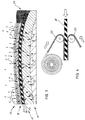
- a geocomposite system 10 forming a road in accordance with the present invention.
- the particular preferred embodiment chosen to illustrate the invention, and best shown in Figure 2 includes a geocomposite layer 12 disposed between a structural layer 14 and a base layer 16 for extending the service life of the road.
- the pavement system 10 is a preferred embodiment that takes full advantage of the present invention, it is to be understood that equivalent systems for extending the service life of roads, bridges, or the like are deemed to be within the broadest aspects of the present invention.
- the geocomposite layer 12 provides a barrier against the penetration or permeation of surface moisture or liquid (S) into the structural layer 14, as well as, upward migration of ground moisture or liquid (G) into the base layer 16.
- geocomposite layer 12 provides a barrier sufficient to prevent the vertical penetration or migration of moisture or liquid between the layers of the geocomposite system 10.
- the geocomposite layer 12, and specifically geotextile backings 20 and 22 retain sufficient porosity to provide a path based on wicking action for the moisture or liquid horizontally along geomembrane 18 out of the geocomposite system 10 to a suitable stabilized edge drain system 24 for release beyond the shoulder of the road.
- the moisture or liquid (S or G) entering the geocomposite system 10 is absorbed and flows or weeps trough the geotextile backings 20 and 22 to the edge drain system 24.
- the edge drain system 24, in the present preferred embodiment, is a trough formed beyond the edge of the emergency travel shoulder T of the pavement system 10.
- the semi-permeable stabilized aggregate stone and/or soil receives the flow of moisture or liquid from the geotextile backings 20 and 22 and directs it away from the road.
- edge drain system 24 is one commonly utilized along roadways and in other applications, it is to be understood that other like systems for moving moisture or liquids away from the geocomposite system 10 are deemed to be within the broadest aspects of the present invention.
- a sub-surface geotextile wrapped permeable pipe with spaced weep passages directed away from the shoulder could also perform the function.
- the geocomposite layer 12 is both flexible and elastic. Advantageously, these properties allow the geocomposite layer 12 to conform to the structural layer 14 and the base layer 16. This allows the dynamic loading of passing vehicles to be transferred directly through the geocomposite layer 12 which acts as a stress absorption layer above the structural layer 14. This is of increased importance in geocomposite systems wherein the structural layer is subjected to more severe stress, or in transition areas such as between a road and a bridge, for example. Absent these stress absorption properties, the geocomposite layer 12 would transmit all loads into the structural layer from the passing vehicles. The reduction or elimination of these undesirable stress loading conditions reduces the proliferation of reflective (or rebound), fatigue and shrinkage cracking in roads or bridges.
- the elasticity of the geomembrane allows the geomembrane 18 to temporarily deform up to 250 percent. This property allows a large portion of the vertical stresses, but especially the lateral stresses, imparted to the base layer by passing vehicles to be cushioned, and in effect absorbed by the geomembrane 18, thus preventing the transfer of stresses to the structural layer 14. As noted above, this increases the overall tensile strength of the structural layer 14 and the durability of the geocomposite system, and decreases the possibility of excessive sub grade deformation which may occur resulting in pavement cracking, rutting and other distresses.
- the preferred geocomposite system 10 includes the geocomposite layer 12 disposed between the structural layer 14 and the base layer 16.
- the structural layer 14 (shown in Figure 2) includes a sub grade 26, an aggregate layer 28, and a treated aggregate layer 30.
- the base layer 16 comprises a base hot-mix asphalt course 32 and a wear hot-mix asphalt course 34.
- the geocomposite layer 12 is specifically disposed between the upper most layer of the structural layer 14, i.e., it is between the treated aggregate layer 30 and the base hot-mix asphalt course 32.
- the structural layer 14 and the base layer 16 may include several distinct and varying layers and layer combinations dependent upon the specific road or bridge application. While the preferred structural layer 14 takes full advantage of the present invention, it is to be understood that other combinations and methods for forming the structural layer 14 are deemed to be within the broadest aspects of the present invention.
- the structural layer 14 may include more than one aggregate or treated subbase layer.
- the base layer 16 could include an additional intermediate hot-mix asphalt layer, for example, or it could be made semi-rigid, including a stabilized aggregate layer and/or a concrete slab.
- the placement of the geocomposite layer 12 within the geocomposite system 10 may also vary dependent upon the specific required application.
- the geocomposite layer 12 may alternatively be placed between the base hot-mix asphalt course 32 and the wear hot-mix asphalt course 34 within the base layer 16. This placement may be preferred for certain repair or rehabilitation purposes to reduce fatigue cracking due to its ability to absorb stress/strain energy.
- it could be placed between the sub grade 26 and the aggregate layer 28 within the structural layer 14 for specific wetland applications.
- an alternate embodiment of the present invention includes a geocomposite system 40 for a bridge having a geocomposite layer 42 disposed between a structural layer 44 and a base layer or overlay 46.
- the structural layer 44 includes a bridge deck 48 and a reinforced concrete deck 50, with or without reinforcement bars 52.
- the base layer 46 is simply a hot-mix asphalt wear course 54.
- the geocomposite layer 42 and specifically geotextile backings 56 and 58 provide a wicking action for lateral movement of moisture or liquids along the geomembrane 60 to the channel 62 and weep passages 64.
- the geocomposite system 40 is designed to extend the service life of the bridge primarily by providing a baffler against the penetration of surface moisture or liquid into the structural layer 44. More specifically, the geocomposite system 40 protects the bridge deck 48 and the reinforcement bars 52 from the corrosive properties typically associated with moisture and other liquids, such as chloride ions and other solutions, that result from use of ice and snow control materials in the colder climates and/or splashing of seawater.
- the geocomposite layer 12 is completely fabricated and quality tested prior to installation in the road geocomposite system 10 or bridge geocomposite system 40.
- this provides a superior quality and uniformity than was heretofore available with prior road or bridge geocomposite systems where the impermeable barriers are formed at the worksite.
- the geomembrane 18 is a plastic or rubber web.
- the web is selected from the group consisting of polyvinylchloride, a very flexible polyethylene, a linear low density polyethylene, a low density linear polyethylene, an ethylene propylene diene terpolymer, or a chlorosuphonated polyethylene and has a thickness in the range of 30 to 100 millimeters.
- the geomembrane 18 is an extruded polyvinyichloride plastic web with a thickness in the range of 60 to 100 millimeters and most preferably, the thickness is substantially 80 millimeters.
- a 20 millimeter plastic or rubber membrane is sufficient to provide the impermeable barrier capable of preventing the migration or permeation of moisture or liquid.
- a 20 millimeter membrane provides no margin to protect against damage during construction.
- the present preferred geomembrane 18 inherently provides a margin (50 to 400 percent) against damage during construction, or during repair work, such as resurfacing.
- the geotextile backings 20 and 22 are fabricated of a mat of non-woven polyester or polypropylene fibers having a density in the range of 100-400 grams per square meter (g/m 2 ). Most preferably, the geotextile backings 20 and 22 are non-woven polyester fibers having a density of 150-200 grams per square member (g/m 2 ). As shown in Figure 4, the geotextile backings 20 and 22 are heat bonded to the geomembrane 18, preferably just after extrusion, such as by calendaring or rolling under pressure. The preferred range of thickness of the geomembrane 18 is necessary to accommodate proper bonding, while assuring retention of the proper wicking action in the backings 20, 22.
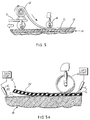
- the fabricated geocomposite layer 12 may be transported to the construction site on a conventional transport vehicle T in a roll (shown in Figure 5a), where it is easily unrolled during construction of the road or bridge.
- the geocomposite layer 12 is formed off-site (see Figure 4), by a calendaring process, and brought to construction site on a trailer T (see Figure 5).
- the structural layer 14 of the road or bridge geocomposite system 10 or 40 is prepared in the cut of the ground or on the bridge deck. It is leveled to receive the geocomposite layer 12.
- a tack coat C 1 forming a suitable adhesive is applied, such as by a sprayer E 1 ( Figure 5a).
- the tack coat C 1 is an asphalt elastormeric composition.
- an emulsified, liquid asphalt which includes bituminous and/or non-bituminous components, can be economically used.
- the composition selected should be capable of assuring that the geotextile backing 20 is securely mechanically bonded to the upper face of the structural layer 14.
- the geocomposite layer 12 is thus laid onto the upper face of the prepared structural layer 14.
- the geotextile backing 20 advantageously generally conforms to the face, and absorbs the tack coat C 1 for bonding.
- an outside force sufficient to insure full conformity of the geocomposite layer 12 to the structural layer 14, and a more complete absorption of the tack coat C 1 , is applied.
- the force may be applied in the form of a conventional road construction roller R. The roller R thus forces the geocomposite layer 12 into intimate contact with the tack coat C 1 and the structural layer 14 so that the geotextile backing 20 is now securely adhered to the structural layer 14.
- the geotextile backing 22 is prepared to receive the base layer 16. Specifically, tack coat C 2 , the same as described above, is sprayed on the geotextile backing 22 by sprayer E 2 .
- the base layer 16, for example, is then formed by a mechanical paver, and simultaneously bonded to the geotextile backing 22.
- a conventional roller (not shown) used in road construction (see the roller R) finishes the road or bridge deck through compacting the base layer 16, and in turn pressing the backing 22 into the tack coat C 2 .
- the road and bridge geocomposite systems 10 and 40 include a geocomposite layer 12 having a geomembrane 18 disposed between two geotextile backings 20, 22, a structural layer 14 for supporting the geocomposite layer 12, and a base layer 16 formed on top of the geocomposite layer 12.
- the geomembrane 18 is impermeable to block the movement of moisture vertically between the structural and base layers 14, 16.
- the geotextile backings 20, 22 are sufficiently porous to provide horizontal wicking action for the moisture or liquids causing it to move harmlessly to the lateral edges of and away from the road or bridge.
- the geomembrane 18 is sufficiently flexible and resilient to conform to the layers 14, 16 of the geocomposite system 10, thereby providing a cushioning effect that is operative in increasing the structural capacity. As a result, reflective, shrinkage and fatigue cracking and other damage is minimized.
Landscapes
- Engineering & Computer Science (AREA)
- Architecture (AREA)
- Civil Engineering (AREA)
- Structural Engineering (AREA)
- Road Paving Structures (AREA)
Applications Claiming Priority (2)
| Application Number | Priority Date | Filing Date | Title |
|---|---|---|---|
| US09/289,858 US20010002497A1 (en) | 1999-04-12 | 1999-04-12 | Geocomposite system for roads and bridges and construction method |
| US289858 | 2002-11-07 |
Publications (2)
| Publication Number | Publication Date |
|---|---|
| EP1045071A2 true EP1045071A2 (de) | 2000-10-18 |
| EP1045071A3 EP1045071A3 (de) | 2001-06-27 |
Family
ID=23113418
Family Applications (1)
| Application Number | Title | Priority Date | Filing Date |
|---|---|---|---|
| EP00107523A Withdrawn EP1045071A3 (de) | 1999-04-12 | 2000-04-07 | Geo-Verbundmembran für Strassee und Brücken und Verfahren zu deren Konstruktion |
Country Status (3)
| Country | Link |
|---|---|
| US (1) | US20010002497A1 (de) |
| EP (1) | EP1045071A3 (de) |
| CA (1) | CA2302117A1 (de) |
Cited By (13)
| Publication number | Priority date | Publication date | Assignee | Title |
|---|---|---|---|---|
| EP1312714A1 (de) * | 2001-11-14 | 2003-05-21 | Rockwool International A/S | Vorrichtung zur Dämpfung von Vibrationen |
| NL1019939C2 (nl) * | 2002-02-11 | 2003-08-13 | Univ Delft Tech | Werkwijze voor het hechten van beton aan een substraat alsmede zo verkregen constructie. |
| GB2424617A (en) * | 2005-02-11 | 2006-10-04 | Fompave Holdings Ltd | A water detention system incorporating a composite drainage membrane |
| NL2003313C2 (nl) * | 2009-07-30 | 2011-02-02 | Jaartsveld Holding B V | Werkwijze en inrichting voor het aanleggen van een bekledingsstrook van betonblokken op een bodemondergrond en betonblokken voor een dergelijke bekledingsstrook. |
| CN102294848A (zh) * | 2011-07-19 | 2011-12-28 | 宜兴市金霸土工合成材料有限公司 | 格栅土工膜 |
| CN101761030B (zh) * | 2008-11-19 | 2012-06-06 | 莫崧桂 | 一种钢铁桥面及其制造方法 |
| CN102505624A (zh) * | 2011-10-17 | 2012-06-20 | 武汉理工大学 | 负弯矩区抗裂的钢-混凝土组合连续梁桥 |
| NL1039592C2 (nl) * | 2012-05-10 | 2013-11-12 | Amazone Holding B V | Wegconstructie. |
| US8834065B2 (en) | 2005-02-11 | 2014-09-16 | Formpave Holdings, Limited | Water detention system incorporating a composite drainage membrane |
| CN106149497A (zh) * | 2015-04-02 | 2016-11-23 | 中国二十冶集团有限公司 | 一种海砂路基边坡稳定结构及施工方法 |
| CN109629361A (zh) * | 2018-12-26 | 2019-04-16 | 陕西鼎固建筑工程有限公司 | 一种路基施工方法 |
| PL127009U1 (pl) * | 2018-02-09 | 2019-08-12 | Zikmund Rakowski | Warstwa wewnętrzna asfaltowych nawierzchni lub powierzchni drogowych |
| CN111441211A (zh) * | 2020-04-10 | 2020-07-24 | 中铁六局集团天津铁路建设有限公司 | 一种炭质软岩-土工合成材料复合路基结构 |
Families Citing this family (26)
| Publication number | Priority date | Publication date | Assignee | Title |
|---|---|---|---|---|
| US7131788B2 (en) * | 2000-02-10 | 2006-11-07 | Advanced Geotech Systems | High-flow void-maintaining membrane laminates, grids and methods |
| US7309188B2 (en) * | 2000-02-10 | 2007-12-18 | Advanced Geotech Systems Llc | Drainable base course for a landfill and method of forming the same |
| US6802669B2 (en) * | 2000-02-10 | 2004-10-12 | Peter J. Ianniello | Void-maintaining synthetic drainable base courses and methods for extending the useful life of paved structures |
| CA2377702C (en) | 2002-03-20 | 2004-03-16 | Diamond J Industries Ltd. | A method of reducing ground disturbance during freeze-thaw cycles and a subsurface insulation material |
| US20030223826A1 (en) * | 2002-03-21 | 2003-12-04 | Ianniello Peter J. | Synthetic alternatives to uniform and non-uniform gradations of structural fill |
| DE10242860B3 (de) * | 2002-09-14 | 2004-01-22 | Dornier Gmbh | Zerlegbare Brücke |
| US7488523B1 (en) * | 2004-02-23 | 2009-02-10 | Polyguard Products, Inc. | Stress-relieving barrier membrane for concrete slabs and foundation walls |
| AT504483B1 (de) * | 2006-12-22 | 2008-06-15 | Univ Wien Tech | Gleitlagerung für betonplatten, verfahren zur herstellung einer betonplatte und bauwerk mit einer gleitlagerung |
| US8353640B2 (en) * | 2008-01-22 | 2013-01-15 | Brock Usa, Llc | Load supporting panel having impact absorbing structure |
| ES2674721T3 (es) | 2007-01-19 | 2018-07-03 | Brock International | Base para un sistema de césped |
| US20090050025A1 (en) * | 2007-08-21 | 2009-02-26 | Tetra Tech, Inc. | Use of Encapsulated Water Soluble Material as a Construction Material |
| US7874767B2 (en) * | 2008-01-24 | 2011-01-25 | Nicolon Corporation | Woven geosynthetic fabric with differential wicking capability |
| NZ590838A (en) * | 2008-07-03 | 2012-06-29 | Infrastructure Technologies Ltd | Laser welded multi layer waterproofing geotextile membrane sheet |
| KR101444989B1 (ko) * | 2008-11-28 | 2014-09-26 | 가부시키가이샤 브릿지 | 포장체, 포장체의 시공 방법 및 콘크리트용 형틀 |
| EP2452017B1 (de) | 2009-07-06 | 2017-12-27 | Brock International | Strukturelles unterlagensystem für pflasterungs- und bodenbelagselemente |
| US20140369750A1 (en) * | 2013-06-14 | 2014-12-18 | Baltazar Siqueiros | Grout containment sheet and method |
| US9085899B1 (en) * | 2014-07-14 | 2015-07-21 | Poly-America, L.P. | Geomembrane to concrete affixing system and method |
| USD866800S1 (en) | 2015-10-26 | 2019-11-12 | Brock Usa, Llc | Turf underlayment |
| US10060082B2 (en) | 2016-05-18 | 2018-08-28 | Brock Usa, Llc | Base for turf system with vertical support extensions at panel edges |
| US10538884B2 (en) | 2017-03-03 | 2020-01-21 | Pavegard Products Inc. | Paving machine membrane dispenser |
| CN112160214B (zh) * | 2020-10-21 | 2022-02-11 | 中国十七冶集团有限公司 | 一种基于路缘石的土工布固定装置及安装方法 |
| US11293159B1 (en) | 2021-01-13 | 2022-04-05 | CB Geotex LLC | Method of maintaining soil strength and stability |
| CN114182593A (zh) * | 2021-12-10 | 2022-03-15 | 天津大学 | 一种增强路基抗震性能的地基加固结构及施工方法 |
| US11542667B1 (en) | 2022-06-28 | 2023-01-03 | Prince Mohammad Bin Fahd University | Flexible pavement structure |
| CN117445516B (zh) * | 2023-11-17 | 2024-11-26 | 山东鑫之源新材料科技有限公司 | 一种土工复合材料及制备工艺 |
| CN120575501B (zh) * | 2025-08-05 | 2025-10-31 | 中建八局第四建设有限公司 | 一种带自动覆膜与热熔切割机构的桥面混凝土覆膜机器人 |
Citations (1)
| Publication number | Priority date | Publication date | Assignee | Title |
|---|---|---|---|---|
| US4362780A (en) | 1978-05-08 | 1982-12-07 | Owens-Corning Fiberglas Corporation | Fiber reinforced membrane paving construction |
Family Cites Families (5)
| Publication number | Priority date | Publication date | Assignee | Title |
|---|---|---|---|---|
| US4251586A (en) * | 1979-09-10 | 1981-02-17 | Owens-Corning Fiberglas Corporation | Road pavement and repair |
| US4503107A (en) * | 1982-07-28 | 1985-03-05 | W. R. Grace & Co. | Construction barrier board |
| DE3444895A1 (de) * | 1984-12-08 | 1986-06-12 | Ed. Züblin AG, 7000 Stuttgart | Vorrichtung zur abdeckung von deponien |
| IT1221382B (it) * | 1988-06-22 | 1990-06-27 | Derbit Derivati Bituminosi Ed | Macchina semovente per la posa in opera di membrane impermeabilizzanti od isolanti |
| DE19543991A1 (de) * | 1995-11-25 | 1997-05-28 | Synteen Gewebetechnik Gmbh | Gewebe zur Armierung von Strukturen |
-
1999
- 1999-04-12 US US09/289,858 patent/US20010002497A1/en not_active Abandoned
-
2000
- 2000-03-27 CA CA002302117A patent/CA2302117A1/en not_active Abandoned
- 2000-04-07 EP EP00107523A patent/EP1045071A3/de not_active Withdrawn
Patent Citations (1)
| Publication number | Priority date | Publication date | Assignee | Title |
|---|---|---|---|---|
| US4362780A (en) | 1978-05-08 | 1982-12-07 | Owens-Corning Fiberglas Corporation | Fiber reinforced membrane paving construction |
Cited By (16)
| Publication number | Priority date | Publication date | Assignee | Title |
|---|---|---|---|---|
| EP1312714A1 (de) * | 2001-11-14 | 2003-05-21 | Rockwool International A/S | Vorrichtung zur Dämpfung von Vibrationen |
| WO2003042457A1 (en) * | 2001-11-14 | 2003-05-22 | Rockwool International A/S | A vibration damping system |
| US7337981B2 (en) | 2001-11-14 | 2008-03-04 | Rockwool International A/S | Vibration damping system |
| NL1019939C2 (nl) * | 2002-02-11 | 2003-08-13 | Univ Delft Tech | Werkwijze voor het hechten van beton aan een substraat alsmede zo verkregen constructie. |
| GB2424617A (en) * | 2005-02-11 | 2006-10-04 | Fompave Holdings Ltd | A water detention system incorporating a composite drainage membrane |
| GB2424617B (en) * | 2005-02-11 | 2011-01-26 | Fompave Holdings Ltd | A water detention system incorporating a composite drainage membrane |
| US8834065B2 (en) | 2005-02-11 | 2014-09-16 | Formpave Holdings, Limited | Water detention system incorporating a composite drainage membrane |
| CN101761030B (zh) * | 2008-11-19 | 2012-06-06 | 莫崧桂 | 一种钢铁桥面及其制造方法 |
| NL2003313C2 (nl) * | 2009-07-30 | 2011-02-02 | Jaartsveld Holding B V | Werkwijze en inrichting voor het aanleggen van een bekledingsstrook van betonblokken op een bodemondergrond en betonblokken voor een dergelijke bekledingsstrook. |
| CN102294848A (zh) * | 2011-07-19 | 2011-12-28 | 宜兴市金霸土工合成材料有限公司 | 格栅土工膜 |
| CN102505624A (zh) * | 2011-10-17 | 2012-06-20 | 武汉理工大学 | 负弯矩区抗裂的钢-混凝土组合连续梁桥 |
| NL1039592C2 (nl) * | 2012-05-10 | 2013-11-12 | Amazone Holding B V | Wegconstructie. |
| CN106149497A (zh) * | 2015-04-02 | 2016-11-23 | 中国二十冶集团有限公司 | 一种海砂路基边坡稳定结构及施工方法 |
| PL127009U1 (pl) * | 2018-02-09 | 2019-08-12 | Zikmund Rakowski | Warstwa wewnętrzna asfaltowych nawierzchni lub powierzchni drogowych |
| CN109629361A (zh) * | 2018-12-26 | 2019-04-16 | 陕西鼎固建筑工程有限公司 | 一种路基施工方法 |
| CN111441211A (zh) * | 2020-04-10 | 2020-07-24 | 中铁六局集团天津铁路建设有限公司 | 一种炭质软岩-土工合成材料复合路基结构 |
Also Published As
| Publication number | Publication date |
|---|---|
| US20010002497A1 (en) | 2001-06-07 |
| CA2302117A1 (en) | 2000-10-12 |
| EP1045071A3 (de) | 2001-06-27 |
Similar Documents
| Publication | Publication Date | Title |
|---|---|---|
| EP1045071A2 (de) | Geo-Verbundmembran für Strassee und Brücken und Verfahren zu deren Konstruktion | |
| KR100476132B1 (ko) | 도로 보강 시트 및 아스팔트 강화 포장 도로의 구조 및도로의 포장 방법 | |
| Nithin et al. | State-of-the art summary of geosynthetic interlayer systems for retarding the reflective cracking | |
| US11479924B2 (en) | Millable, recyclable, waterproofing, paving fabric interlayer system and method of use | |
| US3932051A (en) | Highway construction | |
| JP2016037746A (ja) | 道路橋の埋設継手構造とその施工法 | |
| JPH111901A (ja) | 剛性材料からつくられる道路の新規な構造 | |
| CS265399B1 (en) | Dilatation bridge closing device and method for producing thereof | |
| CZ20041248A3 (cs) | Způsob zpevňování a zajišťování vodotěsnosti jízdního povrchu | |
| Shukla et al. | Functions and installation of paving geosynthetics | |
| GB2390867A (en) | Water management system for managing storm water, spillages etc. | |
| Frosch et al. | Implementation of performance-based bridge deck protective systems. | |
| AU611026B2 (en) | Self-adhesive combination web for preventing and making good cracks, especially in asphalt and concrete surfaces | |
| JP2002322603A (ja) | アスファルト舗装の防水施工方法 | |
| Button et al. | Evaluation of fabric interlayers | |
| JP3467413B2 (ja) | 面状ヒータを埋設したアスファルト舗装構造の形成方法 | |
| KR20230155645A (ko) | 건식 프라임코트 및 이의 제조방법 및 이를 이용한 시공방법 | |
| RU2263186C1 (ru) | Изоляционный материал | |
| JP2916715B2 (ja) | 防水層を有する舗装体 | |
| JPH0893041A (ja) | 排水性舗装における排水構造 | |
| CN108625228B (zh) | 一种耐候沥青混凝土无砟轨道结构 | |
| RU15734U1 (ru) | Покрытие автомобильных дорог | |
| GB2396379A (en) | Water management system | |
| RU2473730C1 (ru) | Дорожная одежда для автомобильных дорог и аэродромных покрытий | |
| WO2025126238A1 (en) | Epoxy asphalt modified concrete (eamc) overlays system for rigid and flexible pavements for road construction and maintenance |
Legal Events
| Date | Code | Title | Description |
|---|---|---|---|
| PUAI | Public reference made under article 153(3) epc to a published international application that has entered the european phase |
Free format text: ORIGINAL CODE: 0009012 |
|
| AK | Designated contracting states |
Kind code of ref document: A2 Designated state(s): AT BE CH CY DE DK ES FI FR GB GR IE IT LI LU MC NL PT SE |
|
| AX | Request for extension of the european patent |
Free format text: AL;LT;LV;MK;RO;SI |
|
| PUAL | Search report despatched |
Free format text: ORIGINAL CODE: 0009013 |
|
| AK | Designated contracting states |
Kind code of ref document: A3 Designated state(s): AT BE CH CY DE DK ES FI FR GB GR IE IT LI LU MC NL PT SE |
|
| AX | Request for extension of the european patent |
Free format text: AL;LT;LV;MK;RO;SI |
|
| RIC1 | Information provided on ipc code assigned before grant |
Free format text: 7E 01C 11/16 A, 7E 01F 5/00 B, 7E 01C 3/06 B, 7E 01D 19/08 B |
|
| AKX | Designation fees paid | ||
| REG | Reference to a national code |
Ref country code: DE Ref legal event code: 8566 |
|
| STAA | Information on the status of an ep patent application or granted ep patent |
Free format text: STATUS: THE APPLICATION IS DEEMED TO BE WITHDRAWN |
|
| 18D | Application deemed to be withdrawn |
Effective date: 20011228 |