EP1045122B1 - Dispositif pour limiter la vitesse d'un moteur et/ou la vitesse d'un vehicule à moteur - Google Patents
Dispositif pour limiter la vitesse d'un moteur et/ou la vitesse d'un vehicule à moteur Download PDFInfo
- Publication number
- EP1045122B1 EP1045122B1 EP00103768A EP00103768A EP1045122B1 EP 1045122 B1 EP1045122 B1 EP 1045122B1 EP 00103768 A EP00103768 A EP 00103768A EP 00103768 A EP00103768 A EP 00103768A EP 1045122 B1 EP1045122 B1 EP 1045122B1
- Authority
- EP
- European Patent Office
- Prior art keywords
- speed
- value
- torque
- ist
- regulator
- Prior art date
- Legal status (The legal status is an assumption and is not a legal conclusion. Google has not performed a legal analysis and makes no representation as to the accuracy of the status listed.)
- Expired - Lifetime
Links
Images

Classifications
-
- F—MECHANICAL ENGINEERING; LIGHTING; HEATING; WEAPONS; BLASTING
- F02—COMBUSTION ENGINES; HOT-GAS OR COMBUSTION-PRODUCT ENGINE PLANTS
- F02D—CONTROLLING COMBUSTION ENGINES
- F02D41/00—Electrical control of supply of combustible mixture or its constituents
- F02D41/02—Circuit arrangements for generating control signals
- F02D41/14—Introducing closed-loop corrections
- F02D41/1497—With detection of the mechanical response of the engine
-
- G—PHYSICS
- G05—CONTROLLING; REGULATING
- G05B—CONTROL OR REGULATING SYSTEMS IN GENERAL; FUNCTIONAL ELEMENTS OF SUCH SYSTEMS; MONITORING OR TESTING ARRANGEMENTS FOR SUCH SYSTEMS OR ELEMENTS
- G05B11/00—Automatic controllers
- G05B11/01—Automatic controllers electric
- G05B11/36—Automatic controllers electric with provision for obtaining particular characteristics, e.g. proportional, integral, differential
- G05B11/42—Automatic controllers electric with provision for obtaining particular characteristics, e.g. proportional, integral, differential for obtaining a characteristic which is both proportional and time-dependent, e.g. P. I., P. I. D.
-
- B—PERFORMING OPERATIONS; TRANSPORTING
- B60—VEHICLES IN GENERAL
- B60K—ARRANGEMENT OR MOUNTING OF PROPULSION UNITS OR OF TRANSMISSIONS IN VEHICLES; ARRANGEMENT OR MOUNTING OF PLURAL DIVERSE PRIME-MOVERS IN VEHICLES; AUXILIARY DRIVES FOR VEHICLES; INSTRUMENTATION OR DASHBOARDS FOR VEHICLES; ARRANGEMENTS IN CONNECTION WITH COOLING, AIR INTAKE, GAS EXHAUST OR FUEL SUPPLY OF PROPULSION UNITS IN VEHICLES
- B60K31/00—Vehicle fittings, acting on a single sub-unit only, for automatically controlling vehicle speed, i.e. preventing speed from exceeding an arbitrarily established velocity or maintaining speed at a particular velocity, as selected by the vehicle operator
-
- B—PERFORMING OPERATIONS; TRANSPORTING
- B60—VEHICLES IN GENERAL
- B60W—CONJOINT CONTROL OF VEHICLE SUB-UNITS OF DIFFERENT TYPE OR DIFFERENT FUNCTION; CONTROL SYSTEMS SPECIALLY ADAPTED FOR HYBRID VEHICLES; ROAD VEHICLE DRIVE CONTROL SYSTEMS FOR PURPOSES NOT RELATED TO THE CONTROL OF A PARTICULAR SUB-UNIT
- B60W2710/00—Output or target parameters relating to a particular sub-units
- B60W2710/06—Combustion engines, Gas turbines
- B60W2710/0605—Throttle position
-
- B—PERFORMING OPERATIONS; TRANSPORTING
- B60—VEHICLES IN GENERAL
- B60W—CONJOINT CONTROL OF VEHICLE SUB-UNITS OF DIFFERENT TYPE OR DIFFERENT FUNCTION; CONTROL SYSTEMS SPECIALLY ADAPTED FOR HYBRID VEHICLES; ROAD VEHICLE DRIVE CONTROL SYSTEMS FOR PURPOSES NOT RELATED TO THE CONTROL OF A PARTICULAR SUB-UNIT
- B60W2710/00—Output or target parameters relating to a particular sub-units
- B60W2710/06—Combustion engines, Gas turbines
- B60W2710/0616—Position of fuel or air injector
-
- B—PERFORMING OPERATIONS; TRANSPORTING
- B60—VEHICLES IN GENERAL
- B60W—CONJOINT CONTROL OF VEHICLE SUB-UNITS OF DIFFERENT TYPE OR DIFFERENT FUNCTION; CONTROL SYSTEMS SPECIALLY ADAPTED FOR HYBRID VEHICLES; ROAD VEHICLE DRIVE CONTROL SYSTEMS FOR PURPOSES NOT RELATED TO THE CONTROL OF A PARTICULAR SUB-UNIT
- B60W2710/00—Output or target parameters relating to a particular sub-units
- B60W2710/06—Combustion engines, Gas turbines
- B60W2710/0644—Engine speed
-
- B—PERFORMING OPERATIONS; TRANSPORTING
- B60—VEHICLES IN GENERAL
- B60W—CONJOINT CONTROL OF VEHICLE SUB-UNITS OF DIFFERENT TYPE OR DIFFERENT FUNCTION; CONTROL SYSTEMS SPECIALLY ADAPTED FOR HYBRID VEHICLES; ROAD VEHICLE DRIVE CONTROL SYSTEMS FOR PURPOSES NOT RELATED TO THE CONTROL OF A PARTICULAR SUB-UNIT
- B60W2710/00—Output or target parameters relating to a particular sub-units
- B60W2710/06—Combustion engines, Gas turbines
- B60W2710/0666—Engine torque
Definitions
- the invention relates to a device for speed limitation of engines and / or to limit the speed of motor-driven Motor vehicles, with a regulator, the engine speed adjusted to an applied maximum permissible speed or regulates to a speed that applied one permissible maximum speed.
- the speed limitation takes place by fuel suppression, that is, when exceeding the predetermined Maximum permissible speed limit is the shutdown single cylinder.
- the disadvantages of the known speed limitation consist in that no output of a defined actual torque to external control devices is possible. Because when inserting the speed limit no combustion in stoichiometric Ratio is more possible, the deteriorate Emissions. Furthermore, when switching off and inserting the injection of known speed limits strong torque jumps, which leads to a significant loss of comfort.
- An object of the present invention is to provide a Device for speed limitation and / or speed limitation to create that over conventional devices more comfortable with better. Emission values works, and independent can be used by the engine type used
- the controller is more advantageous Way with means for specifying the torque setpoint in dependence provided the gradient of the controlled variable.
- a subtraction stage then serves to form a Presence torque from the difference between reduction torque and torque actual value. This is with the controller in operative connection to the specification of the torque setpoint in dependence this reserve torque.
- the influence of the Torque setpoint by the gradient of the controlled variable, ie Speed actual value and / or actual speed value, in particular by the inventively formed retention torque contributes significantly to the comfort and allows a gentle Limit.
- a limit function stage is for formation the speed limit function when exceeding a maximum Continuous speed provided by the speed feedback.
- These Boundary function stage preferably has a timer for Specification of a maximum speed lying above the maximum continuous speed for a definable period of time, in which case a ramp generator for returning the maximum speed after expiration the definable time period provided for the maximum continuous speed is.
- This short-term allowance of an excess the maximum continuous speed also leads to the avoidance of Torque shocks, since thereby avoiding such Torque shocks a gentle return to the maximum continuous speed is possible.
- This limit function stage thus prevents even then uncomfortable jolts, if as a result of a strong Torque increase exceeded the maximum continuous speed becomes.
- a subtracting step is expediently for forming the difference between the speed limit function or the speed limit and the actual speed value provided, this Difference can be fed to an input of the controller.
- a first comparison stage when this proviso value is exceeded activated by the controlled variable and / or the controller deactivated when falling below.
- the logic stage can also expediently at least one Have second comparison stage, which falls below a fixed value below the holding value by the controlled variable deactivated the controller. This will be a safe shutdown the regulator ensures when the distance of the controlled variable from the limit has become sufficiently large.
- speed or speed limit is suitable in particular, essentially designed as a PI controller regulator.
- the torque setpoint formed as a manipulated variable is in particular for intervention on means for controlling the control the air and / or fuel supply to the engine provided wherein an intervention on the air supply as special has proved favorable.
- the detected by a conventional speed sensor speed actual value n is an internal combustion engine of a motor vehicle of a gradient 10 is supplied to form a speed gradient n degree .
- This speed gradient is then a function by means of a map 11 N degrees and a torque actual value m is the internal combustion engine formed a reduction torque m red.
- the torque actual value m is thereby usually calculated, for example, from the air mass flow and the engine speed or the amount of fuel supplied and the engine speed is formed.
- the greater is the rotational speed gradient n degree the greater the reduction torque m red.
- this reduction torque m red is subtracted from the torque actual value m ist , and a reserve torque m prevent , which is supplied to a PI controller 13, is obtained. Therefore, this reserve torque m prev therefore affects the controller 13 to the effect that the output manipulated variable, namely the torque setpoint m vorg not only depends on the control deviation, but in addition to the speed gradient n grad . This means that not only the control deviation, but also this reserve torque m vorh acting on the torque setpoint m vorg effect that this is reduced, the greater the speed gradient is n degrees .
- a limit function stage 14 is used to determine the current Abregelfitiere n maxeff for soft speed limitation .
- This Abregeldusiere n maxeff is dependent on the maximum continuous speed n duration , the maximum speed n max and the actual speed value n is formed, as will be explained in more detail in connection with Figures 2 and 3.
- n duration and n max are fixed quantities that are set individually for each type of internal combustion engine.
- a downstream subtracting stage 15 forms the difference value n diff between the actual rotational speed n ist and the regulating speed n maxeff formed in the limit function stage 14. This value is fed as a control variable to the controller 13, which returns this difference value n diff to the value zero by a corresponding reduction of the torque setpoint value m vorg . This means that when exceeding the maximum continuous speed n duration, the speed is gently returned to this value of the continuous speed n duration . This will be explained below with reference to Figures 2 and 3.
- the limit function stage 14 is only activated when the actual speed value n is the maximum continuous speed n duration exceeds. This initialization takes place by means of a comparison stage 16.
- the limit function shown in FIG. 3 is now formed in a downstream function generator 18, to which the maximum speed n max is present as a value. After the initialization at the time t 0 , the value of the maximum speed n max is first predetermined for a definable time duration t 1 . Subsequently, this value is fed back by means of a ramp generator via a ramp to the value of the maximum continuous speed n duration .
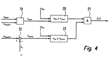
- a logic stage 18 is used to activate (output signal 1) and deactivating (output 0) of the controller 13 as a function of the speed gradient n degrees, the cut-off speed n maxeff and the actual speed value n.
- This logic stage 18 is shown in more detail in Figure 4 and will be explained with reference to Figure 4 below.
- Essential is the determination of a speed gradient dependent speed Vorhalteschwelle n vorg . This is formed in a function stage 19 as a function of the speed gradient n grad and the regulation speed n maxeff . In a subsequent comparison stage 20 it is checked whether the actual speed value n is this speed derivative action threshold shaft reaches or exceeds n prev. In this case, an activation of the controller 13 by means of a Vorhalt bits via an AND stage 21. This ensures that the controller 13 is activated earlier, ie at lower actual rotational speeds, the greater the speed gradient is.
- n limit is formed as a difference between the regulation speed n maxeff and a fixed value n k in a subtraction stage 22. Of course you could specify this shutdown threshold n also directly as a fixed value .
- a downstream comparison stage 23 is now checked whether the actual speed value n is equal to or above this switch-off threshold n limit . In this case, the AND stage 21 is continuous for signals of the comparator 20. In the other case, the AND stage 21 is disabled and the controller 13 is thereby turned off or disabled.
- This deactivation or direct shutdown of the controller 13 can be done without further constraints, however, can Deactivation can also be met further conditions, e.g. can the deactivation will not be completed until the regulator torque receives no penetration.
- Deactivation can also be met further conditions, e.g. can the deactivation will not be completed until the regulator torque receives no penetration.
- the controller 13 which is designated as a PI controller in FIG. 1, can in principle be used also have a different regulator characteristic, e.g. P, I, PID or the like. Depending on regulator specifications Individual controller parts can also be activated or deactivated become.
- the exemplary embodiment described with reference to FIGS. 1 to 4 relates to a device for limiting the speed of motors. Accordingly, however, a device for limiting the speed of motor-driven motor vehicles can be realized, in which case each speed variables are to be replaced by speed variables. It is essential that even in the case of speed limit, the controller 13 sets a torque setpoint for the engine of the motor vehicle as a manipulated variable. A combined device for speed limitation and speed limit can be realized accordingly, in which case the smaller default moment m vorg be given in conflicting specifications, the priority.
- the torque setpoint m vorg formed by the controller as a manipulated variable acts, for example, on an adjusting device for the throttle valve of an internal combustion engine, thus acting on the air supply of the internal combustion engine, which represents a preferred solution.
- the invention is not limited to the speed limitation of internal combustion engines or to the speed limit of combustion-powered motor vehicles, but it can also be applied to other types of engines, such as electric motors.
- the torque setpoint n vorg acts as a manipulated variable, for example via control electronics, on the current and / or voltage supply of the electric motor.
Landscapes
- Engineering & Computer Science (AREA)
- Chemical & Material Sciences (AREA)
- Combustion & Propulsion (AREA)
- Mechanical Engineering (AREA)
- General Engineering & Computer Science (AREA)
- Physics & Mathematics (AREA)
- General Physics & Mathematics (AREA)
- Automation & Control Theory (AREA)
- Electrical Control Of Air Or Fuel Supplied To Internal-Combustion Engine (AREA)
- Controls For Constant Speed Travelling (AREA)
- Output Control And Ontrol Of Special Type Engine (AREA)
- Combined Controls Of Internal Combustion Engines (AREA)
Claims (12)
- Dispositif pour limiter la vitesse de rotation de moteurs, comportant un régulateur (13), qui prédétermine une valeur de consigne (mvorg) du couple pour le moteur en tant que grandeur de réglage, en fonction de la différence (ndiff) entre une valeur réelle (nist) de la vitesse de rotation en tant que grandeur réglée et une valeur limite de la vitesse de rotation ou une fonction limite de la vitesse de rotation (nmaxeff), caractérisé en ce que le régulateur (13) est équipé de moyens (10 - 12) pour la prédétermination de la valeur de consigne du couple (mvorg) en fonction du gradient (ngrad) de la grandeur réglée (nist), que des moyens (11) sont prévus pour former un couple de réduction (mred) en fonction du gradient (ngrad) de la grandeur réglée (nist) et de la valeur réelle (mist) du couple, et qu'un étage de soustraction (12) pour la formation d'un couple de dérivation (mvorh) à partir de la différence entre le couple de réduction (mred) et la valeur réelle (mist) du couple, et qu'un étage soustracteur (12) pour former un couple de dérivation (mvorh) à partir de la différence entre le couple de réduction (mred) et la valeur réelle (mist) du couple coopère avec le régulateur (13) pour la prédétermination de la valeur de consigne (mvorg) du couple en fonction du couple de dérivation (mvorh).
- Dispositif pour limiter la vitesse de véhicules automobiles mûs par un moteur, comportant un régulateur (13) qui prédétermine la valeur de consigne (mvorg) du couple pour le moteur du véhicule automobile en tant que grandeur de réglage en fonction de la différence entre une valeur réelle de vitesse en tant que grandeur réglée et une valeur limite de vitesse ou une fonction limite de vitesse, caractérisé en ce que le régulateur (13) comprend des moyens (10 - 12) pour la prédétermination de la valeur de consigne (mvorg) du couple pour le moteur du véhicule automobile en tant que grandeur réglée, que des moyens (11) sont prévus pour former un couple de réduction (mred) en fonction du gradient (ngrad) de la grandeur réglée (nist) et de la valeur réelle (mist) du couple, et qu'un étage soustracteur (12) pour la formation d'un couple de dérivation (mvorh) à partir de la différence entre le couple de réduction (mred) et la valeur réelle (mist) du couple, coopère avec le régulateur (13) pour la prédétermination de la valeur de consigne (mvorg) du couple en fonction du couple de dérivation (mvorh).
- Dispositif selon la revendication 1 ou 2, caractérisé en ce qu'il est prévu un champ de caractéristique pour former le couple de réduction (mred).
- Dispositif selon l'une des revendications précédentes, caractérisé en ce qu'il est prévu un étage de fonction limite (14) pour former la fonction limite (nmaxeff) de la vitesse de rotation lorsque la valeur réelle (nist) de la vitesse de rotation dépasse une vitesse de rotation durable maximale (ndauer).
- Dispositif selon la revendication 4, caractérisé en ce que l'état de fonction limite (14) comporte un circuit de minuterie pour prédéterminer une vitesse de rotation maximale (nmax), qui est supérieure à la vitesse de rotation durable maximale (ndauer), pour une durée (t1) pouvant être fixée, et qu'un générateur de signaux à rampe est prévu pour ramener la vitesse de rotation maximale (nmax) à la vitesse de rotation du couple maximal (mdauer) après l'écoulement de la durée (t1) pouvant être fixée.
- Dispositif selon la revendication 4 ou 5, caractérisé en ce que la fonction limite de la vitesse de rotation (nmaxeff) est formée en tant que vitesse de rotation de régulation.
- Dispositif selon l'une des revendications 4 à 6, caractérisé en ce qu'il est prévu un étage soustracteur (15) pour former la différence (ndiff) entre la fonction limite de vitesse de rotation (nmaxeff) ou la valeur limite de la vitesse de rotation et la valeur réelle (nist) de la vitesse de rotation, cette différence (ndiff) pouvant être envoyée à une entrée du régulateur (13).
- Dispositif selon l'une des revendications précédentes, caractérisé en ce qu'il est prévu un étage logique (18) pour former une valeur de dérivation en fonction du gradient (ngrad) de la grandeur réglée (nist) et de la valeur limite ou de la fonction limite (nmaxeff), un premier étage comparateur (20) activant le régulateur (13) lorsque la grandeur de régulation (nist) dépasse par le haut cette valeur de dérivation (nvorh) et/ou le désactivant dans le cas où cette grandeur de régulation tombe au-dessus de cette valeur de dérivation.
- Dispositif selon la revendication 8, caractérisé en ce que l'étage logique (18) comporte au moins un second étage comparateur (23), qui désactive le régulateur (13) lorsque la grandeur réglée (nist) tombe au-dessous d'une valeur (ngrenz) inférieure à la valeur de dérivation (nvorh).
- Dispositif selon l'une des revendications précédentes, caractérisé en ce que le régulateur (13) est agencé essentiellement sous la forme d'un régulateur PI (à action proportionnelle et intégrale).
- Dispositif selon l'une des revendications précédentes, caractérisé en ce que la valeur de consigne (mvorg) du couple, prise en tant que grandeur de réglage, est prévue pour appliquer une action à des dispositifs pour la commande ou la régulation de l'apport d'air et/ou de carburant au moteur.
- Dispositif selon la revendication 11, caractérisé en ce que lors de l'action, les processus de combustion s'effectuent essentiellement selon un rapport stoechiométrique, c'est-à-dire lambda = 1.
Applications Claiming Priority (4)
| Application Number | Priority Date | Filing Date | Title |
|---|---|---|---|
| DE19916491 | 1999-04-13 | ||
| DE19916491 | 1999-04-13 | ||
| DE19926351A DE19926351C2 (de) | 1999-04-13 | 1999-06-10 | Vorrichtung zur Drehzahlbegrenzung von Motoren und/oder zur Geschwindigkeitsbegrenzung von motorbetriebenen Kraftfahrzeugen |
| DE19926351 | 1999-06-10 |
Publications (3)
| Publication Number | Publication Date |
|---|---|
| EP1045122A2 EP1045122A2 (fr) | 2000-10-18 |
| EP1045122A3 EP1045122A3 (fr) | 2002-03-20 |
| EP1045122B1 true EP1045122B1 (fr) | 2005-04-13 |
Family
ID=26052873
Family Applications (1)
| Application Number | Title | Priority Date | Filing Date |
|---|---|---|---|
| EP00103768A Expired - Lifetime EP1045122B1 (fr) | 1999-04-13 | 2000-02-23 | Dispositif pour limiter la vitesse d'un moteur et/ou la vitesse d'un vehicule à moteur |
Country Status (2)
| Country | Link |
|---|---|
| US (1) | US6363910B1 (fr) |
| EP (1) | EP1045122B1 (fr) |
Families Citing this family (6)
| Publication number | Priority date | Publication date | Assignee | Title |
|---|---|---|---|---|
| JP4082231B2 (ja) * | 2003-02-17 | 2008-04-30 | 日産自動車株式会社 | エンジンの過回転防止制御装置 |
| DE102007011737A1 (de) * | 2007-03-10 | 2008-09-11 | Bayerische Motoren Werke Aktiengesellschaft | Vorrichtung und Verfahren zur Steuerung einer Brennkraftmaschine eines Kraftfahrzeugs |
| JP4872789B2 (ja) * | 2007-05-10 | 2012-02-08 | トヨタ自動車株式会社 | 車両駆動ユニットの制御装置 |
| DE102007035097B4 (de) | 2007-07-26 | 2016-05-19 | Robert Bosch Gmbh | Verfahren und Vorrichtung zum Betreiben einer Antriebseinheit |
| WO2015044942A2 (fr) * | 2013-09-30 | 2015-04-02 | Corning Optical Communications Wireless Ltd. | Détermination de l'efficacité d'une source de signaux optiques dans des systèmes de communication répartis |
| JP6221858B2 (ja) * | 2014-03-13 | 2017-11-01 | 株式会社豊田自動織機 | 産業車両の走行制御装置 |
Family Cites Families (12)
| Publication number | Priority date | Publication date | Assignee | Title |
|---|---|---|---|---|
| US4217867A (en) * | 1979-05-29 | 1980-08-19 | General Motors Corporation | Low overshoot engine speed governor |
| US4693077A (en) * | 1986-07-18 | 1987-09-15 | General Motors Corporation | Closed-loop engine control with feedback torque error compensation |
| JPS63109264A (ja) * | 1986-10-27 | 1988-05-13 | Honda Motor Co Ltd | 内燃機関の高回転時出力制限装置 |
| DE3728574C1 (de) * | 1987-08-27 | 1988-11-24 | Daimler Benz Ag | Einrichtung zum Regeln des Antriebsmomentes eines Kraftfahrzeuges |
| JPH01167440A (ja) * | 1987-12-22 | 1989-07-03 | Mazda Motor Corp | エンジンの過回転防止装置 |
| DE3937846A1 (de) | 1989-11-14 | 1991-05-16 | Wolf Geraete Gmbh Vertrieb | Drehzahlregelanordnung fuer brennkraftmaschinen |
| US5392215A (en) * | 1992-08-17 | 1995-02-21 | Mitsubishi Denki Kabushiki Kaisha | Automatic cruising speed controller for an automotive vehicle |
| DE4434022C2 (de) | 1994-09-23 | 1999-11-11 | Daimler Chrysler Ag | Verfahren und Vorrichtung zur Geschwindigkeitsbegrenzung eines Kraftfahrzeuges |
| DE19506082A1 (de) * | 1995-02-22 | 1996-08-29 | Bosch Gmbh Robert | Verfahren und Vorrichtung zur Steuerung der Antriebseinheit eines Fahrzeugs |
| DE19509492C2 (de) * | 1995-03-16 | 1998-08-27 | Daimler Benz Ag | Verfahren und Vorrichtung zur Geschwindigkeitsbegrenzung eines Kraftfahrzeuges |
| KR0174095B1 (ko) * | 1995-07-21 | 1999-03-20 | 전성원 | 자동차의 속도 제한 제어방법 |
| US6078859A (en) * | 1997-08-04 | 2000-06-20 | Ford Global Technologies, Inc. | System and method for torque based vehicle speed control |
-
2000
- 2000-02-23 EP EP00103768A patent/EP1045122B1/fr not_active Expired - Lifetime
- 2000-04-10 US US09/546,102 patent/US6363910B1/en not_active Expired - Fee Related
Also Published As
| Publication number | Publication date |
|---|---|
| EP1045122A3 (fr) | 2002-03-20 |
| EP1045122A2 (fr) | 2000-10-18 |
| US6363910B1 (en) | 2002-04-02 |
Similar Documents
| Publication | Publication Date | Title |
|---|---|---|
| DE3880146T2 (de) | Steuerung von aufladenen brennkraftmaschinen. | |
| DE2820807C2 (fr) | ||
| DE2749369A1 (de) | Steuereinrichtung fuer ein magnetventil im umgehungskanal einer drosselklappe bei brennkraftmaschinen | |
| DE10332231A1 (de) | Anordnung und Verfahren zur leistungsbasierten Leerlaufdrehzahlregelung | |
| DE69418611T2 (de) | Verfahren und vorrichtung zur steuerung der leerlauf-drehzahl einer innenbrennkraftmaschine | |
| EP1005609B1 (fr) | Procede permettant de commander le recyclage des gaz d'echappement d'un moteur a combustion interne | |
| DE19947109B4 (de) | Vorrichtung und Verfahren zum Steuern von Brennkraftmaschinen | |
| EP1045122B1 (fr) | Dispositif pour limiter la vitesse d'un moteur et/ou la vitesse d'un vehicule à moteur | |
| DE3924953C2 (fr) | ||
| DE4305573A1 (de) | Verfahren und Vorrichtung zur Steuerung einer Antriebseinheit eines Fahrzeugs | |
| DE10114040B4 (de) | Verfahren und Vorrichtung zur Steuerung der Antriebseinheit eines Fahrzeugs | |
| EP0168412A1 (fr) | Procede et dispositif de regulation de la vitesse de rotation d'un moteur a combustion interne | |
| EP1277940B1 (fr) | Procédé et dispositif de commande d'un moteur d'entraînement | |
| DE19926351C2 (de) | Vorrichtung zur Drehzahlbegrenzung von Motoren und/oder zur Geschwindigkeitsbegrenzung von motorbetriebenen Kraftfahrzeugen | |
| DE69411011T2 (de) | Verfahren und vorrichtung zur steuerung der leerlauf-drehzahl einer innenbrennkraftmaschine | |
| EP0460126B1 (fr) | Systeme pour la commande electronique et/ou la regulation de la puissance d'un moteur a combustion interne d'un vehicule automobile | |
| EP0089409A1 (fr) | Système de coupure d'alimentation en carburant dans un moteur à combustion interne | |
| DE10249098A1 (de) | Verfahren und Vorrichtung zur Steuerung einer Antriebseinheit mit einer Brennkraftmaschine | |
| DE69401503T2 (de) | Verfahren zur steuerung einer brennkraftmaschine beim schalten im leerlaufdrehzahlbereich | |
| DE4426972B4 (de) | Verfahren und Vorrichtung zur Steuerung einer Brennkraftmaschine | |
| DE102007017489A1 (de) | Brennstoffsteuersystem für einen Motor | |
| DE4303560A1 (de) | Verfahren und Vorrichtung zur Steuerung einer Verstelleinrichtung | |
| DE102005048419A1 (de) | Einlaßmengensteuervorrichtung für einen Verbrennungsmotor | |
| EP1474598B1 (fr) | Dispositif pour reguler le moment de rotation d'une unite d'entrainement d'un vehicule | |
| EP0740058B1 (fr) | Procédé pour ajuster le mouvement d'un organe de réglage variateur de charge |
Legal Events
| Date | Code | Title | Description |
|---|---|---|---|
| PUAI | Public reference made under article 153(3) epc to a published international application that has entered the european phase |
Free format text: ORIGINAL CODE: 0009012 |
|
| AK | Designated contracting states |
Kind code of ref document: A2 Designated state(s): DE FR GB IT Kind code of ref document: A2 Designated state(s): AT BE CH CY DE DK ES FI FR GB GR IE IT LI LU MC NL PT SE |
|
| AX | Request for extension of the european patent |
Free format text: AL;LT;LV;MK;RO;SI |
|
| PUAL | Search report despatched |
Free format text: ORIGINAL CODE: 0009013 |
|
| AK | Designated contracting states |
Kind code of ref document: A3 Designated state(s): AT BE CH CY DE DK ES FI FR GB GR IE IT LI LU MC NL PT SE |
|
| AX | Request for extension of the european patent |
Free format text: AL;LT;LV;MK;RO;SI |
|
| 17P | Request for examination filed |
Effective date: 20020207 |
|
| AKX | Designation fees paid |
Free format text: DE FR GB IT |
|
| GRAP | Despatch of communication of intention to grant a patent |
Free format text: ORIGINAL CODE: EPIDOSNIGR1 |
|
| GRAS | Grant fee paid |
Free format text: ORIGINAL CODE: EPIDOSNIGR3 |
|
| GRAA | (expected) grant |
Free format text: ORIGINAL CODE: 0009210 |
|
| RBV | Designated contracting states (corrected) |
Designated state(s): FR GB IT |
|
| AK | Designated contracting states |
Kind code of ref document: B1 Designated state(s): FR GB IT |
|
| REG | Reference to a national code |
Ref country code: GB Ref legal event code: FG4D Free format text: NOT ENGLISH |
|
| REG | Reference to a national code |
Ref country code: DE Ref legal event code: 8566 |
|
| REG | Reference to a national code |
Ref country code: IE Ref legal event code: FG4D Free format text: LANGUAGE OF EP DOCUMENT: GERMAN |
|
| GBT | Gb: translation of ep patent filed (gb section 77(6)(a)/1977) |
Effective date: 20050517 |
|
| PLBE | No opposition filed within time limit |
Free format text: ORIGINAL CODE: 0009261 |
|
| STAA | Information on the status of an ep patent application or granted ep patent |
Free format text: STATUS: NO OPPOSITION FILED WITHIN TIME LIMIT |
|
| ET | Fr: translation filed | ||
| 26N | No opposition filed |
Effective date: 20060116 |
|
| REG | Reference to a national code |
Ref country code: FR Ref legal event code: CA Ref country code: FR Ref legal event code: CD |
|
| PGFP | Annual fee paid to national office [announced via postgrant information from national office to epo] |
Ref country code: FR Payment date: 20110302 Year of fee payment: 12 Ref country code: IT Payment date: 20110221 Year of fee payment: 12 |
|
| PGFP | Annual fee paid to national office [announced via postgrant information from national office to epo] |
Ref country code: GB Payment date: 20110217 Year of fee payment: 12 |
|
| GBPC | Gb: european patent ceased through non-payment of renewal fee |
Effective date: 20120223 |
|
| REG | Reference to a national code |
Ref country code: FR Ref legal event code: ST Effective date: 20121031 |
|
| PG25 | Lapsed in a contracting state [announced via postgrant information from national office to epo] |
Ref country code: IT Free format text: LAPSE BECAUSE OF NON-PAYMENT OF DUE FEES Effective date: 20120223 |
|
| PG25 | Lapsed in a contracting state [announced via postgrant information from national office to epo] |
Ref country code: FR Free format text: LAPSE BECAUSE OF NON-PAYMENT OF DUE FEES Effective date: 20120229 Ref country code: GB Free format text: LAPSE BECAUSE OF NON-PAYMENT OF DUE FEES Effective date: 20120223 |