EP1045150B1 - Wegeventil - Google Patents
Wegeventil Download PDFInfo
- Publication number
- EP1045150B1 EP1045150B1 EP00107278A EP00107278A EP1045150B1 EP 1045150 B1 EP1045150 B1 EP 1045150B1 EP 00107278 A EP00107278 A EP 00107278A EP 00107278 A EP00107278 A EP 00107278A EP 1045150 B1 EP1045150 B1 EP 1045150B1
- Authority
- EP
- European Patent Office
- Prior art keywords
- directional control
- port
- control valve
- displacement
- pressing member
- Prior art date
- Legal status (The legal status is an assumption and is not a legal conclusion. Google has not performed a legal analysis and makes no representation as to the accuracy of the status listed.)
- Expired - Lifetime
Links
- 238000006073 displacement reaction Methods 0.000 claims description 29
- XEEYBQQBJWHFJM-UHFFFAOYSA-N Iron Chemical group [Fe] XEEYBQQBJWHFJM-UHFFFAOYSA-N 0.000 claims description 24
- 238000004891 communication Methods 0.000 claims description 14
- 230000009471 action Effects 0.000 claims description 9
- 230000007246 mechanism Effects 0.000 claims description 7
- 239000012530 fluid Substances 0.000 description 15
- 239000007788 liquid Substances 0.000 description 6
- 238000000034 method Methods 0.000 description 3
- 230000008569 process Effects 0.000 description 3
- 238000005406 washing Methods 0.000 description 3
- 229920002943 EPDM rubber Polymers 0.000 description 2
- 230000008878 coupling Effects 0.000 description 2
- 238000010168 coupling process Methods 0.000 description 2
- 238000005859 coupling reaction Methods 0.000 description 2
- 230000003247 decreasing effect Effects 0.000 description 2
- 230000000694 effects Effects 0.000 description 2
- WABPQHHGFIMREM-UHFFFAOYSA-N lead(0) Chemical compound [Pb] WABPQHHGFIMREM-UHFFFAOYSA-N 0.000 description 2
- 238000007796 conventional method Methods 0.000 description 1
- 238000012423 maintenance Methods 0.000 description 1
- 239000000463 material Substances 0.000 description 1
- 239000011347 resin Substances 0.000 description 1
- 229920005989 resin Polymers 0.000 description 1
- 238000007789 sealing Methods 0.000 description 1
- 229920002379 silicone rubber Polymers 0.000 description 1
Images



Classifications
-
- F—MECHANICAL ENGINEERING; LIGHTING; HEATING; WEAPONS; BLASTING
- F16—ENGINEERING ELEMENTS AND UNITS; GENERAL MEASURES FOR PRODUCING AND MAINTAINING EFFECTIVE FUNCTIONING OF MACHINES OR INSTALLATIONS; THERMAL INSULATION IN GENERAL
- F16K—VALVES; TAPS; COCKS; ACTUATING-FLOATS; DEVICES FOR VENTING OR AERATING
- F16K11/00—Multiple-way valves, e.g. mixing valves; Pipe fittings incorporating such valves
- F16K11/02—Multiple-way valves, e.g. mixing valves; Pipe fittings incorporating such valves with all movable sealing faces moving as one unit
- F16K11/04—Multiple-way valves, e.g. mixing valves; Pipe fittings incorporating such valves with all movable sealing faces moving as one unit comprising only lift valves
- F16K11/052—Multiple-way valves, e.g. mixing valves; Pipe fittings incorporating such valves with all movable sealing faces moving as one unit comprising only lift valves with pivoted closure members, e.g. butterfly valves
- F16K11/0525—Multiple-way valves, e.g. mixing valves; Pipe fittings incorporating such valves with all movable sealing faces moving as one unit comprising only lift valves with pivoted closure members, e.g. butterfly valves the closure members being pivoted around an essentially central axis
-
- F—MECHANICAL ENGINEERING; LIGHTING; HEATING; WEAPONS; BLASTING
- F15—FLUID-PRESSURE ACTUATORS; HYDRAULICS OR PNEUMATICS IN GENERAL
- F15B—SYSTEMS ACTING BY MEANS OF FLUIDS IN GENERAL; FLUID-PRESSURE ACTUATORS, e.g. SERVOMOTORS; DETAILS OF FLUID-PRESSURE SYSTEMS, NOT OTHERWISE PROVIDED FOR
- F15B13/00—Details of servomotor systems ; Valves for servomotor systems
- F15B13/02—Fluid distribution or supply devices characterised by their adaptation to the control of servomotors
- F15B13/04—Fluid distribution or supply devices characterised by their adaptation to the control of servomotors for use with a single servomotor
- F15B13/0401—Valve members; Fluid interconnections therefor
- F15B13/0405—Valve members; Fluid interconnections therefor for seat valves, i.e. poppet valves
-
- F—MECHANICAL ENGINEERING; LIGHTING; HEATING; WEAPONS; BLASTING
- F15—FLUID-PRESSURE ACTUATORS; HYDRAULICS OR PNEUMATICS IN GENERAL
- F15B—SYSTEMS ACTING BY MEANS OF FLUIDS IN GENERAL; FLUID-PRESSURE ACTUATORS, e.g. SERVOMOTORS; DETAILS OF FLUID-PRESSURE SYSTEMS, NOT OTHERWISE PROVIDED FOR
- F15B13/00—Details of servomotor systems ; Valves for servomotor systems
- F15B13/02—Fluid distribution or supply devices characterised by their adaptation to the control of servomotors
- F15B13/04—Fluid distribution or supply devices characterised by their adaptation to the control of servomotors for use with a single servomotor
- F15B13/044—Fluid distribution or supply devices characterised by their adaptation to the control of servomotors for use with a single servomotor operated by electrically-controlled means, e.g. solenoids, torque-motors
-
- F—MECHANICAL ENGINEERING; LIGHTING; HEATING; WEAPONS; BLASTING
- F16—ENGINEERING ELEMENTS AND UNITS; GENERAL MEASURES FOR PRODUCING AND MAINTAINING EFFECTIVE FUNCTIONING OF MACHINES OR INSTALLATIONS; THERMAL INSULATION IN GENERAL
- F16K—VALVES; TAPS; COCKS; ACTUATING-FLOATS; DEVICES FOR VENTING OR AERATING
- F16K31/00—Actuating devices; Operating means; Releasing devices
- F16K31/02—Actuating devices; Operating means; Releasing devices electric; magnetic
- F16K31/06—Actuating devices; Operating means; Releasing devices electric; magnetic using a magnet, e.g. diaphragm valves, cutting off by means of a liquid
- F16K31/0682—Actuating devices; Operating means; Releasing devices electric; magnetic using a magnet, e.g. diaphragm valves, cutting off by means of a liquid with an articulated or pivot armature
-
- Y—GENERAL TAGGING OF NEW TECHNOLOGICAL DEVELOPMENTS; GENERAL TAGGING OF CROSS-SECTIONAL TECHNOLOGIES SPANNING OVER SEVERAL SECTIONS OF THE IPC; TECHNICAL SUBJECTS COVERED BY FORMER USPC CROSS-REFERENCE ART COLLECTIONS [XRACs] AND DIGESTS
- Y10—TECHNICAL SUBJECTS COVERED BY FORMER USPC
- Y10T—TECHNICAL SUBJECTS COVERED BY FORMER US CLASSIFICATION
- Y10T137/00—Fluid handling
- Y10T137/8593—Systems
- Y10T137/86493—Multi-way valve unit
- Y10T137/86574—Supply and exhaust
- Y10T137/86622—Motor-operated
-
- Y—GENERAL TAGGING OF NEW TECHNOLOGICAL DEVELOPMENTS; GENERAL TAGGING OF CROSS-SECTIONAL TECHNOLOGIES SPANNING OVER SEVERAL SECTIONS OF THE IPC; TECHNICAL SUBJECTS COVERED BY FORMER USPC CROSS-REFERENCE ART COLLECTIONS [XRACs] AND DIGESTS
- Y10—TECHNICAL SUBJECTS COVERED BY FORMER USPC
- Y10T—TECHNICAL SUBJECTS COVERED BY FORMER US CLASSIFICATION
- Y10T137/00—Fluid handling
- Y10T137/8593—Systems
- Y10T137/86493—Multi-way valve unit
- Y10T137/86847—Pivoted valve unit
Definitions
- the present invention relates to a directional control valve which makes it possible to control the flow direction of a pressure fluid.
- the directional control valve has been hitherto used in order to control the flow direction of the pressure fluid.
- a directional control valve includes, for example, a three-port solenoid-operated valve for operating a valve plug with a solenoid.
- the three-port solenoid-operated valve has three ports including a pressure fluid supply port, an output port, and a discharge port.
- the pressure fluid supply port and the output port are formed coaxially respectively via a communication passage on opposing side surface portions of a casing.
- the discharge port is formed in a direction substantially perpendicular to an axis obtained by connecting the pressure fluid supply port and the output port.
- the valve plug for opening/closing the communication passage in accordance with the displacement action of the valve plug is arranged between the pressure fluid supply port and the output port. When the valve plug is separated from a seat section to open the communication passage, the pressure fluid supply port communicates with the output port.
- the output port communicates with the discharge port when the valve plug is seated on the seat section to give the valve-closed state.
- the pressure fluid supply port communicates with the output port.
- a general object of the present invention is to provide a directional control valve which makes it possible to realize a small size and a light weight of the entire apparatus by suppressing its dimension in the widthwise direction substantially perpendicular to the axis of a main valve body.
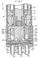
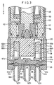
- reference numeral 10 indicates a three-way valve according to an embodiment of the present invention.
- the three-way valve 10 has a casing 12 which is formed to have a bottom-equipped hollow rectangular parallelepiped-shaped configuration, and a valve body 14 which is integrally connected to the casing 12.
- the casing 12 and the valve body 14 function as a main valve body.
- a closed space 16 is formed at the inside of the casing 12 and the valve body 14.
- a solenoid section 18 and a valve mechanism section 20 are coaxially arranged closely to one another in the space 16.
- the valve body 14 comprises a block member 24 which has a substantially rectangular parallelepiped-shaped configuration with a hole 22 (see FIG. 5) having an elliptic cross section formed at a central portion, and a plate member 26 which is fixed to a bottom surface portion of the block member 24.
- An end edge of a diaphragm 28 is interposed at a connecting portion between the block member 24 and the plate member 26.
- the diaphragm 28 has a flat thin-walled section 30 which is formed at a substantially central portion, and a first expanded section 32a and a second expanded section 32b which have a semispherical configuration and which are separated from each other by a predetermined spacing distance.
- first and second expanded sections 32a, 32b are designed such that they are seated on a first seat section 34a and a second seat section 34b formed on the plate member 26 respectively.
- the region between the first and second seat sections 34a, 34b is formed to give a substantially flat surface.
- a chamber 36 is formed between the diaphragm 28 and the plate member 26.
- each of the first and second seat sections 34a, 34b is formed by a tapered surface with its diameter which is gradually decreased downwardly (in the direction of the arrow B).
- each of the first and second seat sections 34a, 34b may be formed by a flat surface in place of the tapered surface.
- a first projection 38a, a second projection 38b, a third projection 38c which have a cylindrical configuration and which protrude in the axial direction of the casing 12, are formed at the bottom of the plate member 26.
- First to third ports 40a to 40c are provided in juxtaposition on the first to third projections 38a to 38c via communication holes communicating with the chamber 36 respectively.
- the diaphragm 28 is preferably formed of, for example, silicon rubber or EPDM (ethylene-propylene-diene terpolymer).
- the solenoid section 18 includes a holding means 42 which is provided at the inside of the casing 12, a fixed iron core 44 which has a substantially columnar configuration and which is fixed to an upper surface portion of the holding means 42, an electromagnetic coil 48 which is externally fitted to the fixed iron core 44 with a coil wound in a plurality of turns via a bobbin 46, and a movable iron core 50 which is provided displaceably along a hole formed in the bobbin 46 with a predetermined clearance provided with respect to a first end of the fixed iron core 44 in the axial direction.
- the electric power is applied to the electromagnetic coil 48 via a lead wire 52 connected to an unillustrated power source.
- a circuit board 54 is arranged between the lead wire 52 and the electromagnetic coil 48.
- the valve mechanism section 20 includes a displacement member 58 which is coaxially connected to the first end of the movable iron core 50 via a coupling member 56 and which is displaceable integrally with the movable iron core 50 along the hole 22 having the elliptic cross section, and a first spring member 62 which is fastened between the coupling member 56 and a receiving member 60, for urging the displacement member 58 downwardly (in the direction of the arrow B) in accordance with the action of the resilient force.
- a displacement member 58 which is coaxially connected to the first end of the movable iron core 50 via a coupling member 56 and which is displaceable integrally with the movable iron core 50 along the hole 22 having the elliptic cross section
- a first spring member 62 which is fastened between the coupling member 56 and a receiving member 60, for urging the displacement member 58 downwardly (in the direction of the arrow B) in accordance with the action of the resilient force.
- a pair of holes 64a, 64b which have different diameters and which are separated from each other by a predetermined spacing distance to extend in the axial direction, are formed in the displacement member 58.
- a first pressing member 66a having a substantially columnar configuration is inserted and fitted into the first hole 64a having the smaller diameter.
- a second pressing member 66b having a substantially columnar configuration is loosely fitted via a gap to the second hole 64b having the large diameter.
- the respective axes of the first pressing member 66a and the second pressing member 66b are designed such that they are substantially parallel to the axis of the movable iron core 50 and the displacement member 58 and they are separated from the axis by an identical distance.
- Substantially hemispherical expanded sections 67a, 67b are formed at first ends of the first and second pressing members 66a, 66b protruding from the holes 64a, 64b of the displacement member 58 respectively.
- the gap is formed between the outer circumferential surface of the second pressing member 66b and the wall surface of the hole 64b.
- a second spring member 68 for pressing the second pressing member 66b downwardly (in the direction of the arrow B) is arranged in the gap.
- the resilient force (spring force) of the second spring member 68 is set to be about a half of that of the first spring member 62.
- a swinging member 72 which makes swinging displacement by a predetermined angle about a supporting point of a shaft member 70 supported by the block member 24 for rotation, is arranged under the displacement member 58.
- the shaft member 70 is attached for rotation at a substantially central portion of the swinging member 72 formed to have a flat plate configuration.
- the expanded sections 67a, 67b of the first pressing member 66a and the second pressing member 66b which are separated from each other by the predetermined spacing distance, make point-to-point contact with the substantially flat upper surface of the swinging member 72 respectively.
- the diaphragm 28, which functions as a valve plug, is secured to the bottom surface of the swinging member 72.
- the swinging member 72 is inclined slanting downward to the left about the supporting point of the shaft member 70 in accordance with the pressing action of the first pressing member 66a, and the first expanded section 32a is seated on the first seat section 34a.
- the first port 40a is closed to give a communication state between the second port 40b and the third port 40c.
- the swinging member 72 is inclined slanting downward to the right about the supporting point of the shaft member 70 in accordance with the pressing action of the second pressing member 66b, and the second expanded section 32b is seated on the second seat section 34b.
- the third port 40c is closed to give a communication state between the first port 40a and the second port 40b.
- the communication state between the second port 40b and the third port 40c and the communication state between the first port 40a and the second port 40b are mutually switched to one another in accordance with the swinging action of the swinging member 72.
- the three-way valve 10 according to the embodiment of the present invention is basically constructed as described above. Next, its operation, function, and effect will be explained.
- an unillustrated tube is previously installed to the first projection 38a to communicate and connect the first port 40a and an unillustrated washing solution supply source.
- An unillustrated tube is previously installed to the third projection 38c to communicate the third port 40c and an unillustrated liquid supply source.
- An unillustrated tube is previously installed to the second projection 38b to communicate and connect the second port 40b and an unillustrated fluid pressure-operated apparatus.
- the fixed iron core 44 is separated from the movable iron core 50 to form a predetermined clearance 74 therebetween.
- the swinging member 72 is inclined slanting downward to the left, and thus the first expanded section 32a is seated on the first seat section 34a. Accordingly, the first port 40a is closed, and the second port 40b and the third port 40c are in the communication state. The following description will be made assuming that this state is the initial state.
- the unillustrated liquid is supplied from the third port 40c, and it is discharged from the second port 40b via the chamber 36, giving a state in which the liquid is supplied to the unillustrated fluid pressure-operated apparatus.
- the unillustrated power source is energized to allow a current to flow through the electromagnetic coil 48. Accordingly, the electromagnetic coil 48 is excited.
- the movable iron core 50 is attracted toward the fixed iron core 44 (in the direction of the arrow A) in accordance with the attractive force generated by the exciting action of the electromagnetic coil 48. Therefore, the displacement member 58 is displaced by a predetermined spacing distance upwardly (in the direction of the arrow A) integrally with the movable iron core 50 against the resilient force of the first spring member 62. Accordingly, the force to press the first end side of the swinging member 72 by the first pressing member 66a is decreased. Simultaneously, the force to press the second end side of the swinging member 72 by the second spring member 68 fastened to the second pressing member 66b is increased.
- the swinging member 72 makes the swinging movement about the supporting point of the shaft member 70 from the state slanting downward to the left to the state slanting downward to the right.
- the second expanded section 32b is seated on the second seat section 34b to close the third port 40c, giving the state in which the first port 40a communicates with the second port 40b. Therefore, the third port 40c for supplying the liquid is closed.
- the washing solution which is supplied via the first port 40a, is introduced into the fluid pressure-operated apparatus via the chamber 36 and the second port 40b.
- the attractive force for the movable iron core 50 disappears.
- the movable iron core 50 and the displacement member 58 are displaced downwardly (in the direction of the arrow B) in accordance with the resilient force of the first spring member 62.
- the force, which is exerted to press the movable iron core 50 and the displacement member 58 in the direction of the arrow B in accordance with the resilient force of the first spring member 62 is divided substantially equivalently, and it is given to the first pressing member 66a and the second pressing member 66b provided in the displacement member 58.
- the force which is exerted to press the first end side of the swinging member 72 by the first pressing member 66a, overcomes the resilient force of the second spring member 68 fastened to the second pressing member 66b. Accordingly, the swinging member 72 makes the swinging displacement by a predetermined angle about the center of the shaft member 70 to restore the initial state.
- the first to third ports 40a to 40c are provided in juxtaposition on the first side surface having the narrow width of the valve body 14.
- the movable iron core 50, the displacement member 58, and the swinging member 72 are arranged coaxially. Thus, it is possible to suppress the dimension in the widthwise direction and realize a small size of the entire apparatus.
- the other constitutive elements except for, for example, the fixed iron core 44 and the movable iron core 50 are formed of the resin material. Accordingly, it is possible to realize a light weight of the entire apparatus.
- first and second expanded sections 32a, 32b are formed on the diaphragm 28.
- the first and second expanded sections 32a, 32b are seated on the first and second seat sections 34a, 34b respectively. Accordingly, the sealing performance is improved, and it is possible to make the seal in a reliable manner.
- Each of the first seat section 34a and the second seat section 34b is formed by the tapered surface, or each of them is formed by the substantially flat surface. Accordingly, it is possible to avoid occurrence of any liquid pool at a region in the vicinity of the seat section.
- FIGS. 6 to 9 a three-way valve 80 according to another embodiment of the present invention is shown in FIGS. 6 to 9.
- the three-way valve 80 has the following feature. That is, a lever 82, which extends in a direction substantially perpendicular to the axis, is provided. When the lever 82 is manually pressed, the swinging member 72 successfully makes swinging displacement to switch the valve position.
- the valve position can be switched in accordance with the manual operation. Therefore, the three-way valve 80 according to the another embodiment is advantageous in that it is especially convenient when the current for the electromagnetic coil 48 is broken due to power interruption or the like, or when the maintenance operation is performed.
Landscapes
- Engineering & Computer Science (AREA)
- General Engineering & Computer Science (AREA)
- Mechanical Engineering (AREA)
- Physics & Mathematics (AREA)
- Fluid Mechanics (AREA)
- Magnetically Actuated Valves (AREA)
- Multiple-Way Valves (AREA)
Claims (11)
- Richtungssteuerventil mit:einem Hauptventilkörper (12, 14) mit einer Vielzahl von Anschlussöffnungen (40a bis 40c) an einer ersten Seitenfläche;einem Elektromagnetabschnitt (18), der im Inneren des Hauptventilkörpers (12, 14) vorgesehen ist und einen festen Eisenkern (44), einen beweglichen Eisenkern (50) und eine Spule (48) aufweist; undeinem Ventilmechanismusabschnitt (20), der einen Ventilstopfen (28) aufweist, welcher koaxial zu dem Elektromagnetabschnitt (18) im Inneren des Hauptventilkörpers (12, 14) angeordnet ist, um Verbindungszustände der Vielzahl von Anschlussöffnungen (40a bis 40c) durch Verschiebung entsprechend der Erregungswirkung der Spule (48) zu schalten, dadurch gekennzeichnet,dass der Ventilmechanismusabschnitt (20) ein Verschiebungselement (48), das mit einem ersten Ende des beweglichen Eisenkerns (50) verbunden ist, ein erstes Federelement (62) zum Pressen des Verschiebungselementes (58) zu der Vielzahl von Anschlussöffnungen (40a bis 40c), ein erstes Presselement (66a) und ein zweites Presselement (66b), die in dem Verschiebungselement (58) im Wesentlichen parallel zu einer Achse des Verschiebungselementes (58) vorgesehen sind, ein zweites Federelement (68), das an dem zweiten Presselement (66b) befestigt ist, und ein Schwenkelement (72) für den Eingriff mit dem ersten Presselement (66a) an einer ersten Endseite und für den Eingriff mit dem zweiten Presselement (66b) an einer zweiten Endseite aufweist, wobei das Schwenkelement (72) eine Schwenkverschiebung um einen Haltpunkt eines Schaftelementes (70), der an einem zentralen Rotationsbereich befestigt ist, durchführt.
- Richtungssteuerventil nach Anspruch 1, wobei der feste Eisenkern (44), das Verschiebungselement (58) und das Schwenkelement (72) jeweils koaxial angeordnet sind.
- Richtungssteuerventil nach Anspruch 1, wobei das erste Presselement (66a) und das zweite Presselement (66b) sich im Wesentlichen parallel zu der Achse des Verschiebungselementes (58) erstrecken und sie angeordnet sind, indem sie voneinander gleiche Abstände aufweisen, wobei die Achse des Verschiebungselementes (58) zwischen ihnen angeordnet ist.
- Richtungssteuerventil nach Anspruch 1, wobei das zweite Federelement (68) so eingestellt ist, dass es eine Federkraft aufweist, die im Wesentlichen die Hälfte derjenigen des ersten Federelementes (62) ist.
- Richtungssteuerventil nach Anspruch 1, wobei die Vielzahl von Anschlussöffnungen (40a bis 40c) linear angeordnet ist, indem sie voneinander um gleiche Abstände an der ersten Seitenfläche mit enger Breite des Hauptventilkörpers (12, 14) getrennt sind.
- Richtungssteuerventil nach Anspruch 1, wobei halbkugelförmige erweiterte Abschnitte (67a, 67b) an ersten Enden in der axialen Richtung des ersten Presselementes (66a) bzw. des zweiten Presselementes (66b) ausgebildet sind, und wobei die erweiterten Abschnitte (67a, 67b) so vorgesehen sind, dass sie in Punktkontakt mit einem flachen Oberflächenbereich des Schwenkelementes (72) treten.
- Richtungssteuerventil nach Anspruch 1, wobei das erste Presselement (66a) in eine Öffnung (64a) des Verschiebungselementes (68) eingesetzt ist, um sich in einer integrierten Weise zu verschieben, und wobei das zweite Presselement (66b) lose über ein zweites Federelement (68) in eine Öffnung (64b) des Verschiebungselementes (58) eingesetzt ist.
- Richtungssteuerventil nach Anspruch 5, wobei die Vielzahl von Anschlussöffnungen eine erste Anschlussöffnung (40a), die an einer ersten Endseite der ersten Oberfläche angeordnet ist, eine zweite Anschlussöffnung (40b), die an einem im Wesentlichen zentralen Bereich angeordnet ist, und eine dritte Anschlussöffnung (40c), die an einer zweiten Endseite angeordnet ist, aufweist und wobei ein Verbindungszustand zwischen der ersten Anschlussöffnung (40a) und der zweiten Anschlussöffnung (40b) und ein Verbindungszustand zwischen der zweiten Anschlussöffnung (40b) und der dritten Anschlussöffnung (40c) entsprechend einer Vorspannwirkung des Ventilmechanismusabschnitts (20) wechselweise umschaltbar sind.
- Richtungssteuerventil nach Anspruch 1, wobei ein Schaltmechanismus zum Umschalten einer Ventilposition des Ventilstopfens (28) durch manuelle Betätigung an dem Hauptventilkörper (14) vorgesehen ist.
- Richtungssteuerventil nach Anspruch 9, wobei der Schaltmechanismus einen Hebel (82), der in einer Richtung im Wesentlichen senkrecht zu der Achse des Hauptventilkörpers (14) verschiebbar vorgesehen ist, einen Vorsprung (92) zum Verschieben des beweglichen Eisenkerns (50) zu dem festen Eisenkern (44) durch Eingriff an einer geneigten Oberfläche (90), die an dem Hebel (82) ausgebildet ist, und einen als Schaft dienenden Stift (86) zum Abstützen des Hebels (82), aufweist.
- Richtungssteuerventil nach Anspruch 1, wobei der Ventilstopfen aus einer Membran (28) besteht, die an dem Schwenkelement (72) befestigt ist, um integral mit dem Schwenkelement (72) eine Schwenkbewegung durchzuführen, und wobei die Membran (28) einen ersten erweiterten Abschnitt (32a) und einen zweiten erweiterten Abschnitt (32b) aufweist, die jeweils eine halbkugelförmige Gestalt aufweisen, um auf einem ersten Sitzabschnitt (34a) bzw. einem zweiten Sitzabschnitt (34b) aufgesetzt zu werden.
Applications Claiming Priority (2)
| Application Number | Priority Date | Filing Date | Title |
|---|---|---|---|
| JP10725399A JP4247566B2 (ja) | 1999-04-14 | 1999-04-14 | バルブ |
| JP10725399 | 1999-04-14 |
Publications (3)
| Publication Number | Publication Date |
|---|---|
| EP1045150A2 EP1045150A2 (de) | 2000-10-18 |
| EP1045150A3 EP1045150A3 (de) | 2003-10-15 |
| EP1045150B1 true EP1045150B1 (de) | 2005-01-12 |
Family
ID=14454373
Family Applications (1)
| Application Number | Title | Priority Date | Filing Date |
|---|---|---|---|
| EP00107278A Expired - Lifetime EP1045150B1 (de) | 1999-04-14 | 2000-04-04 | Wegeventil |
Country Status (7)
| Country | Link |
|---|---|
| US (1) | US6318408B1 (de) |
| EP (1) | EP1045150B1 (de) |
| JP (1) | JP4247566B2 (de) |
| KR (1) | KR100365515B1 (de) |
| CN (1) | CN1112529C (de) |
| DE (1) | DE60017310T2 (de) |
| TW (1) | TW442621B (de) |
Families Citing this family (31)
| Publication number | Priority date | Publication date | Assignee | Title |
|---|---|---|---|---|
| US6820669B2 (en) * | 2002-10-07 | 2004-11-23 | Tezzen Wheel Corporation | Wheel with extended outer flange |
| DE10313484A1 (de) * | 2003-03-26 | 2004-10-07 | Zf Friedrichshafen Ag | Schaltventil mit kurzer Schaltzeit |
| JP4265965B2 (ja) * | 2003-12-03 | 2009-05-20 | シーケーディ株式会社 | 小型電磁弁の製造方法 |
| US7000890B2 (en) * | 2004-01-14 | 2006-02-21 | Cooper Cameron Corporation | Pressure compensated shear seal solenoid valve |
| JP4273499B2 (ja) * | 2004-07-23 | 2009-06-03 | Smc株式会社 | 電磁弁 |
| CN101101069B (zh) * | 2006-07-04 | 2010-12-22 | 深圳迈瑞生物医疗电子股份有限公司 | 微型阀 |
| DE102006031567A1 (de) * | 2006-07-07 | 2008-01-10 | Siemens Ag | Einspritzsystem und Verfahren zum Herstellen eines Einspritzsystems |
| CN101548123B (zh) | 2006-10-12 | 2011-06-08 | 弗路德自动控制系统有限公司 | 摇杆阀机构和摇杆阀 |
| DE502007004672D1 (de) | 2007-12-08 | 2010-09-16 | Asco Joucomatic Gmbh | Vorrichtung zur Durchflussregelung eines flüssigen oder gasförmigen Mediums |
| DE202009016447U1 (de) * | 2009-12-03 | 2010-03-11 | Bürkert Werke GmbH | Fluidisches Steuerelement |
| DE102009058164A1 (de) | 2009-12-15 | 2011-06-16 | Svm Schultz Verwaltungs-Gmbh & Co. Kg | Ventil mit einem Betätigungsglied |
| EP2353731A1 (de) * | 2010-01-27 | 2011-08-10 | Robatech AG | Elektroauftragskopf zum Abgeben eines fliessfähigen Mediums und Vorrichtung mit einem solchen Elektroauftragskopf |
| ITBS20100165A1 (it) * | 2010-10-13 | 2012-04-14 | Camozzi S P A Societa Unipersonal E | Valvola di controllo di un fluido |
| ITBS20100166A1 (it) * | 2010-10-13 | 2012-04-14 | Camozzi S P A Societa Unipersonal E | Valvola di controllo di un fluido |
| DE102012005093A1 (de) | 2012-03-14 | 2013-09-19 | Festo Ag & Co. Kg | Membranventil |
| DE102012005122B4 (de) | 2012-03-14 | 2014-04-10 | Festo Ag & Co. Kg | Membranventil |
| DE202013100678U1 (de) | 2013-02-14 | 2013-03-05 | Bürkert Werke GmbH | Membranventil |
| US9482360B2 (en) * | 2013-07-15 | 2016-11-01 | Parker-Hannifin Corporation | Miniature high performance solenoid valve |
| DE102013110029C5 (de) | 2013-09-12 | 2017-03-16 | Bürkert Werke GmbH | Elektrodynamischer Aktor |
| JP6228439B2 (ja) * | 2013-11-26 | 2017-11-08 | 住友ゴム工業株式会社 | 弁装置 |
| JP6228450B2 (ja) | 2013-12-24 | 2017-11-08 | 住友ゴム工業株式会社 | 弁装置 |
| JP6190338B2 (ja) * | 2014-08-20 | 2017-08-30 | 株式会社コガネイ | 電磁弁 |
| JP6190340B2 (ja) | 2014-08-27 | 2017-08-30 | 株式会社コガネイ | 電磁弁 |
| CN104676074A (zh) * | 2015-02-12 | 2015-06-03 | 深圳垦拓流体控制有限公司 | 一种直动式电磁阀 |
| CN104676075B (zh) * | 2015-02-12 | 2017-08-11 | 深圳垦拓流体控制有限公司 | 一种改进型电磁阀 |
| CN104696552B (zh) * | 2015-02-12 | 2017-06-20 | 深圳垦拓流体控制有限公司 | 一种新型电磁阀 |
| JP6404246B2 (ja) * | 2016-01-29 | 2018-10-10 | 株式会社鷺宮製作所 | 電磁切換弁 |
| CN106286887A (zh) * | 2016-10-10 | 2017-01-04 | 深圳市晶感科技开发有限公司 | 一种电磁阀用密封组件及带有该密封组件的电磁阀 |
| CN110195787B (zh) * | 2018-02-27 | 2024-11-05 | 宁波佳音机电科技股份有限公司 | 电磁阀 |
| DE102021201140A1 (de) | 2021-02-08 | 2022-08-11 | Festo Se & Co. Kg | Magnetventil und Verfahren zum Justieren eines Magnetantriebs für ein Magnetventil |
| US20250102074A1 (en) * | 2023-09-25 | 2025-03-27 | Applied Materials, Inc. | Proportional fluid flow valve and methods of operating thereof |
Family Cites Families (14)
| Publication number | Priority date | Publication date | Assignee | Title |
|---|---|---|---|---|
| US2935086A (en) * | 1955-04-18 | 1960-05-03 | Samuel K Lehman | Pilot operated valve assembly |
| JPS5533922A (en) * | 1978-08-28 | 1980-03-10 | Toyooki Kogyo Co Ltd | Solenoid valve |
| USRE34261E (en) * | 1981-11-06 | 1993-05-25 | Solenoid valve | |
| JPS6051376U (ja) * | 1983-09-16 | 1985-04-11 | 矢崎総業株式会社 | 3方電磁弁 |
| JPS60260783A (ja) * | 1984-06-05 | 1985-12-23 | Takashi Hosokawa | 高頻度電磁弁 |
| US4729544A (en) * | 1987-05-07 | 1988-03-08 | Baumann Hans D | Electric-powered, lever-amplified actuating means for valves and other devices |
| JPH0352476A (ja) * | 1989-07-20 | 1991-03-06 | Fujitsu General Ltd | 文字放送受信機 |
| DE4222594A1 (de) * | 1992-07-09 | 1994-01-13 | Roemer J C Avs Gmbh | Ventil |
| DE4224389B4 (de) * | 1992-07-23 | 2004-02-19 | AVS, Ing. J.C. Römer GmbH | Ventil mit T-förmigem bzw. N-förmigem, wippenartigem Ventilglied |
| EP0628729B1 (de) | 1993-05-07 | 1998-09-02 | Smc Kabushiki Kaisha | Wegeventil und Ventilanordnung für Wegeventile |
| EP0661484B1 (de) * | 1993-11-30 | 1999-08-25 | Smc Corporation | Doppel-Elektromagnetventil |
| EP0704648B1 (de) | 1994-04-18 | 2002-12-11 | Smc Kabushiki Kaisha | Schaltventil |
| DE19718408A1 (de) * | 1997-04-30 | 1998-11-05 | Nass Magnet Gmbh | Mehrwegeventil |
| KR19990016968U (ko) * | 1997-10-31 | 1999-05-25 | 정몽규 | 유압제어용 솔레노이드 밸브 |
-
1999
- 1999-04-14 JP JP10725399A patent/JP4247566B2/ja not_active Expired - Fee Related
-
2000
- 2000-04-04 EP EP00107278A patent/EP1045150B1/de not_active Expired - Lifetime
- 2000-04-04 DE DE60017310T patent/DE60017310T2/de not_active Expired - Lifetime
- 2000-04-05 US US09/543,547 patent/US6318408B1/en not_active Expired - Lifetime
- 2000-04-06 TW TW089106271A patent/TW442621B/zh not_active IP Right Cessation
- 2000-04-10 KR KR1020000018733A patent/KR100365515B1/ko not_active Expired - Fee Related
- 2000-04-14 CN CN00106581A patent/CN1112529C/zh not_active Expired - Fee Related
Also Published As
| Publication number | Publication date |
|---|---|
| EP1045150A3 (de) | 2003-10-15 |
| DE60017310D1 (de) | 2005-02-17 |
| JP4247566B2 (ja) | 2009-04-02 |
| EP1045150A2 (de) | 2000-10-18 |
| CN1112529C (zh) | 2003-06-25 |
| CN1270289A (zh) | 2000-10-18 |
| JP2000297876A (ja) | 2000-10-24 |
| TW442621B (en) | 2001-06-23 |
| KR20000071627A (ko) | 2000-11-25 |
| US6318408B1 (en) | 2001-11-20 |
| DE60017310T2 (de) | 2006-03-02 |
| KR100365515B1 (ko) | 2002-12-18 |
Similar Documents
| Publication | Publication Date | Title |
|---|---|---|
| EP1045150B1 (de) | Wegeventil | |
| EP1134470B1 (de) | Elektromagnetventil | |
| US6719268B2 (en) | Solenoid-operated valve | |
| EP1219877B1 (de) | Selbsthaltendes Elektromagnetventil | |
| US6026860A (en) | Solenoid valve apparatus for two end-users | |
| US5615710A (en) | Pilot-type change-over valve | |
| US3765644A (en) | Controlled air gap in a solenoid operated valve | |
| US4674540A (en) | Valve device | |
| US20030030020A1 (en) | Solenoid-operated valve | |
| US6883545B2 (en) | Three-way switching valve | |
| JP2004011680A (ja) | 三方切換弁 | |
| JPH0238768A (ja) | 流体制御弁 | |
| KR100461935B1 (ko) | 전자밸브 | |
| GB2119481A (en) | Switching valve | |
| JPH0483981A (ja) | 電磁バルブ | |
| JP2839329B2 (ja) | 電磁可逆弁装置 | |
| GB2110795A (en) | Electro-pneumatic valve | |
| JP3408637B2 (ja) | ポペット形方向切換弁 | |
| JP2583766Y2 (ja) | パイロット形電磁弁 | |
| JP4280266B2 (ja) | 流体遮断弁 | |
| JPH0425523Y2 (de) | ||
| JP2889358B2 (ja) | 3方弁のハウジング構造 | |
| JPS631097Y2 (de) | ||
| JPH0320187A (ja) | 方向制御弁 | |
| JPH0531283Y2 (de) |
Legal Events
| Date | Code | Title | Description |
|---|---|---|---|
| PUAI | Public reference made under article 153(3) epc to a published international application that has entered the european phase |
Free format text: ORIGINAL CODE: 0009012 |
|
| AK | Designated contracting states |
Kind code of ref document: A2 Designated state(s): AT BE CH CY DE DK ES FI FR GB GR IE IT LI LU MC NL PT SE |
|
| AX | Request for extension of the european patent |
Free format text: AL;LT;LV;MK;RO;SI |
|
| PUAL | Search report despatched |
Free format text: ORIGINAL CODE: 0009013 |
|
| AK | Designated contracting states |
Kind code of ref document: A3 Designated state(s): AT BE CH CY DE DK ES FI FR GB GR IE IT LI LU MC NL PT SE |
|
| AX | Request for extension of the european patent |
Extension state: AL LT LV MK RO SI |
|
| 17P | Request for examination filed |
Effective date: 20040218 |
|
| AKX | Designation fees paid |
Designated state(s): DE FR GB |
|
| GRAP | Despatch of communication of intention to grant a patent |
Free format text: ORIGINAL CODE: EPIDOSNIGR1 |
|
| GRAS | Grant fee paid |
Free format text: ORIGINAL CODE: EPIDOSNIGR3 |
|
| GRAA | (expected) grant |
Free format text: ORIGINAL CODE: 0009210 |
|
| AK | Designated contracting states |
Kind code of ref document: B1 Designated state(s): DE FR GB |
|
| REG | Reference to a national code |
Ref country code: GB Ref legal event code: FG4D |
|
| REF | Corresponds to: |
Ref document number: 60017310 Country of ref document: DE Date of ref document: 20050217 Kind code of ref document: P |
|
| REG | Reference to a national code |
Ref country code: IE Ref legal event code: FG4D |
|
| PLBE | No opposition filed within time limit |
Free format text: ORIGINAL CODE: 0009261 |
|
| STAA | Information on the status of an ep patent application or granted ep patent |
Free format text: STATUS: NO OPPOSITION FILED WITHIN TIME LIMIT |
|
| ET | Fr: translation filed | ||
| 26N | No opposition filed |
Effective date: 20051013 |
|
| REG | Reference to a national code |
Ref country code: FR Ref legal event code: PLFP Year of fee payment: 17 |
|
| REG | Reference to a national code |
Ref country code: FR Ref legal event code: PLFP Year of fee payment: 18 |
|
| PGFP | Annual fee paid to national office [announced via postgrant information from national office to epo] |
Ref country code: DE Payment date: 20170419 Year of fee payment: 18 Ref country code: FR Payment date: 20170419 Year of fee payment: 18 Ref country code: GB Payment date: 20170419 Year of fee payment: 18 |
|
| REG | Reference to a national code |
Ref country code: DE Ref legal event code: R119 Ref document number: 60017310 Country of ref document: DE |
|
| GBPC | Gb: european patent ceased through non-payment of renewal fee |
Effective date: 20180404 |
|
| PG25 | Lapsed in a contracting state [announced via postgrant information from national office to epo] |
Ref country code: DE Free format text: LAPSE BECAUSE OF NON-PAYMENT OF DUE FEES Effective date: 20181101 |
|
| PG25 | Lapsed in a contracting state [announced via postgrant information from national office to epo] |
Ref country code: GB Free format text: LAPSE BECAUSE OF NON-PAYMENT OF DUE FEES Effective date: 20180404 |
|
| PG25 | Lapsed in a contracting state [announced via postgrant information from national office to epo] |
Ref country code: FR Free format text: LAPSE BECAUSE OF NON-PAYMENT OF DUE FEES Effective date: 20180430 |