EP1045193A1 - Beleuchtungseinrichtung zur Konzentration des Axiallichtes mit abgewinkeltem, konvergierendem Reflektor - Google Patents
Beleuchtungseinrichtung zur Konzentration des Axiallichtes mit abgewinkeltem, konvergierendem Reflektor Download PDFInfo
- Publication number
- EP1045193A1 EP1045193A1 EP99107169A EP99107169A EP1045193A1 EP 1045193 A1 EP1045193 A1 EP 1045193A1 EP 99107169 A EP99107169 A EP 99107169A EP 99107169 A EP99107169 A EP 99107169A EP 1045193 A1 EP1045193 A1 EP 1045193A1
- Authority
- EP
- European Patent Office
- Prior art keywords
- light
- reference axis
- reflective
- lighting device
- refractive
- Prior art date
- Legal status (The legal status is an assumption and is not a legal conclusion. Google has not performed a legal analysis and makes no representation as to the accuracy of the status listed.)
- Withdrawn
Links
- 230000005855 radiation Effects 0.000 claims description 9
- 239000011248 coating agent Substances 0.000 claims description 5
- 238000000576 coating method Methods 0.000 claims description 5
- 230000001154 acute effect Effects 0.000 claims 1
- 230000003287 optical effect Effects 0.000 description 23
- 230000002093 peripheral effect Effects 0.000 description 14
- 239000011347 resin Substances 0.000 description 7
- 229920005989 resin Polymers 0.000 description 7
- 230000007704 transition Effects 0.000 description 6
- 238000004519 manufacturing process Methods 0.000 description 4
- 239000000126 substance Substances 0.000 description 4
- 229920002972 Acrylic fiber Polymers 0.000 description 3
- 239000004593 Epoxy Substances 0.000 description 3
- 230000004048 modification Effects 0.000 description 3
- 238000012986 modification Methods 0.000 description 3
- 230000008901 benefit Effects 0.000 description 2
- 238000010276 construction Methods 0.000 description 2
- 238000000034 method Methods 0.000 description 2
- 230000005540 biological transmission Effects 0.000 description 1
- 238000005266 casting Methods 0.000 description 1
- 230000008859 change Effects 0.000 description 1
- 239000003086 colorant Substances 0.000 description 1
- 239000012141 concentrate Substances 0.000 description 1
- 239000000463 material Substances 0.000 description 1
- 238000000465 moulding Methods 0.000 description 1
- 230000009467 reduction Effects 0.000 description 1
- 238000001228 spectrum Methods 0.000 description 1
Images


Classifications
-
- H—ELECTRICITY
- H10—SEMICONDUCTOR DEVICES; ELECTRIC SOLID-STATE DEVICES NOT OTHERWISE PROVIDED FOR
- H10H—INORGANIC LIGHT-EMITTING SEMICONDUCTOR DEVICES HAVING POTENTIAL BARRIERS
- H10H20/00—Individual inorganic light-emitting semiconductor devices having potential barriers, e.g. light-emitting diodes [LED]
- H10H20/80—Constructional details
- H10H20/85—Packages
- H10H20/852—Encapsulations
- H10H20/853—Encapsulations characterised by their shape
-
- F—MECHANICAL ENGINEERING; LIGHTING; HEATING; WEAPONS; BLASTING
- F21—LIGHTING
- F21V—FUNCTIONAL FEATURES OR DETAILS OF LIGHTING DEVICES OR SYSTEMS THEREOF; STRUCTURAL COMBINATIONS OF LIGHTING DEVICES WITH OTHER ARTICLES, NOT OTHERWISE PROVIDED FOR
- F21V5/00—Refractors for light sources
- F21V5/04—Refractors for light sources of lens shape
-
- F—MECHANICAL ENGINEERING; LIGHTING; HEATING; WEAPONS; BLASTING
- F21—LIGHTING
- F21V—FUNCTIONAL FEATURES OR DETAILS OF LIGHTING DEVICES OR SYSTEMS THEREOF; STRUCTURAL COMBINATIONS OF LIGHTING DEVICES WITH OTHER ARTICLES, NOT OTHERWISE PROVIDED FOR
- F21V7/00—Reflectors for light sources
- F21V7/0091—Reflectors for light sources using total internal reflection
-
- F—MECHANICAL ENGINEERING; LIGHTING; HEATING; WEAPONS; BLASTING
- F21—LIGHTING
- F21L—LIGHTING DEVICES OR SYSTEMS THEREOF, BEING PORTABLE OR SPECIALLY ADAPTED FOR TRANSPORTATION
- F21L4/00—Electric lighting devices with self-contained electric batteries or cells
- F21L4/02—Electric lighting devices with self-contained electric batteries or cells characterised by the provision of two or more light sources
- F21L4/022—Pocket lamps
- F21L4/027—Pocket lamps the light sources being a LED
-
- F—MECHANICAL ENGINEERING; LIGHTING; HEATING; WEAPONS; BLASTING
- F21—LIGHTING
- F21Y—INDEXING SCHEME ASSOCIATED WITH SUBCLASSES F21K, F21L, F21S and F21V, RELATING TO THE FORM OR THE KIND OF THE LIGHT SOURCES OR OF THE COLOUR OF THE LIGHT EMITTED
- F21Y2115/00—Light-generating elements of semiconductor light sources
- F21Y2115/10—Light-emitting diodes [LED]
Definitions
- the present invention relates to a lighting device which is compact and efficient. It can be employed anywhere a concentrated light beam is necessary.
- the present invention would typically be used in a flashlight, a caution light, a light source, a reading light, a display or any of a multiplicity of lighting devices.
- LED element 1P is mounted at the top of a first lead frame 2P and electrically connected to a second lead 3P by a connecting wire 4P.
- These elements comprise a typical light emitting diode (LED) light source 5P.
- LED element 1P emits light forming a spatial radiation pattern that includes both forward and side emitted light.
- the forward emitted light generally includes light emitted within a range of divergence that includes angles of divergence between 0 and 30 degrees from the optical axis XP of the device.
- the side emitted light generally includes light emitted within a range of divergence that includes angles of divergence between 30 and 90 degrees from the optical axis XP of the device.
- LP light source 5P is encapsulated in transparent resin 6P.
- Transparent resin 6P forms two optical light directing surfaces including lens 7P and peripheral reflective surface 8P both which are symmetrical about axis XP. Both optical surfaces are surfaces of revolution about axis XP.
- Peripheral reflective surface 8P is a classical parabolic reflector developed about axis XP and shaped to reflect side emitted light to direct it to become parallel to axis XP.
- peripheral reflective surface 8P typical side emitted light ray R1P emitted from LED element 1P intersects peripheral reflective surface 8P and is reflected such that it becomes parallel to axis XP.
- Planer end portion 9P is perpendicular to reflected light ray R1P and axis XP so planer end portion 9P does not refract reflected light ray R1P or change its direction.
- Interior wall 10P is parallel to both axis XP and reflected light ray R1P so it also does not refract or redirect light.
- Lens 7P refracts forward emitted light to direct it to become more parallel to axis XP.
- typical forward emitted light ray R2P emitted from LED element 1P intersects lens 7P and is refracted to emerge parallel to axis XP.
- Lighting device LP has an outside diameter of dimension D1 and a length of dimension D2.
- the side emitted light is not refracted or redirected after its reflection at peripheral reflective surface 8P.
- the reflected light leaves the device without redirection through a "planar upper surface".
- the referenced prior art design functions , however, it represents an unnecessarily large and massive lighting device.
- the lighting device becomes large because peripheral reflective surface 8P is a parabola contoured to reflect the side light to become parallel to axis XP and also to collect the side light emitted within a wide range of angular divergence from the optical axis XP.
- the undesirably large size of lighting device LP can be reduced but the available methods result in an unacceptable loss in efficiency.
- the size of the peripheral reflective surface 8P alone can be reduced by collecting a reduced angular range of side emitted light but because less light is collected, the efficiency of the device will correspondingly be reduced.
- the size of the entire optical portion of the lighting device LP including the peripheral reflective surface 8P can be proportionally reduced but because LED clement 1P will, if it is to maintain its light output maintain its size the ratio of peripheral reflective surface 8P size verses LED element 1Psize will be reduced. A reduction in this size ratio reduces the ability of the peripheral reflective surface 8P to accurately redirect the side light resulting one again in a loss in efficiency.
- the referenced prior art design is larger than desired.
- the large size increases manufacturing costs and due to shrinkage during molding, reduces the precision of the optical surfaces.
- the larger dimensions of the prior art design require the emitted light to pass through thick sections of transparent resin 6P before exiting the lighting device and consequently experience unacceptable attenuation due to related transmission losses.
- the large prior art lighting device will also not be acceptable for many uses due to the size limitation of many products.
- a main object of the present invention is to provide a lighting device of a more compact design then prior art.
- Another object of the present invention is to provide a lighting device with increased efficiency over prior art.
- Another object of the present invention is to create a lighting device with reduced size and weight.
- Another object of the present invention is to create a lighting device which has reduced mass and which therefore, can be more accurately cast into the precise shape necessary to achieve the highest efficiency of optical design.
- Another object of the present invention is to design a light that provides a concentrated beam pattern.
- a light source comprising a light emitting diode LED element mounted on a lead frame and encapsulated within a transparent resin has a high percentage of its emitted light collected into a light beam concentrated about a reference axis by a combination of optical surfaces.
- the standard light emitting diode element emits light forming a spatial radiation pattern which as described in the referenced prior art can be considered to include a side emitted light zone and a forward emitted light zone. Most of the light energy emitted by the LED element is found within these two zones and the two zones are usually located within a hemisphere.
- the spatial radiation pattern from a typical LED element is usually substantially symmetrical about a pattern axis. However the present invention will function equally well with a variety of other LED element spatial radiation patterns. Some commercially available LED elements emit light with a spatial radiation pattern shaped such that the direction along the pattern axis represents a direction of high intensity.
- the transparent resin of the present invention forms three optical surfaces each which alters the direction of the emitted light.
- each of the optical surfaces is symmetrical about a common reference axis.
- the first optical surface is a lens which refracts emitted light to direct it to become more parallel to a reference axis of the device.
- the second optical surface, a reflector means is a peripheral reflector which reflects and directs emitted light to generally converge towards the reference axis and to intersect the third optical surface, a refractor means.
- the reflector directs the light to generally converge towards the reference axis, it further directs the light to converge towards one or more light concentration points exterior to the reference axis.
- the reflector surface is developed by rotating a line about the reference axis. If the reflector is an elliptical surface the line is an elliptical line curve.
- the parabolic line curve of the referenced prior art is developed about the axis of revolution.
- the parabolic reflector surface of prior art is also developed about the axis of revolution.
- the elliptical line curve of the present invention is developed about two focal points connected by a line which is not the central axis of the device. Line curves which are not elliptical in shape can also be employed to construct the peripheral reflector in the present invention.
- the refractor means is located to intersect the converging light previously reflected by the second optical surface.
- the contour of the refractor must be designed to cooperate with the contour of the reflector to redirect the converging light so that it emerges from the lighting device more parallel to the reference axis of the lighting device then it was when it was first emitted from the LED element.
- the refractor includes a surface which is developed by moving a curved or bent line about the reference axis.
- the refractor will be a curved surface.
- the refractor will be developed from a bent line which is curved. If the reflector is a series of connected parabolic surface segments each reflecting light to intersect the reference plane at different angles then the refraction will be a series of corresponding connected non-coliniar straight line segments.
- the refractor will be developed from a bent line with each of its segments redirecting light reflected by a corresponding parabolic surface segment.
- the reflector (optic 2) and refractor (optic 3) combination of the present invention cooperate to first reflect and direct the light to converge towards the reference axis of the lighting device and then refract and redirect the light to emerge substantially parallel to the reference axis.
- the combination of two cooperating optics permit the present design to be both more compact and more efficient then prior art.
- the present invention concentrates the light about a reference axis creating the concentrated beam pattern required by many specifications.
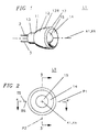
- PIG. 1 is a perspective view of lighting device L1 according to a first embodiment of the present invention.
- FIG. 2 is a front view of the FIG. 1 lighting device.
- FIG. 3 is a cross-sectional view of the FIG. 2 lighting device taken across line 3 - 3' of FIG. 2.
- FIG. 4 is a cross-sectional view of the FIG. 2 lighting device taken across line 4 - 4' of FIG. 2.
- FIG. 5 is an enlarged diagrammatic line drawing of a portion of the FIG.3 drawing showing the contour of portions of the reflector, refractor and lens.
- FIG. 6 is a perspective view of an alternate embodiment of the lighting device according to the present invention.
- FIG. 7 is a front view of the FIG. 6 lighting device.
- FIG. 8 is a perspective view of the FIG. 6 lighting device with the light source separated from the sleeve.
- FIG. 9 is a cross-sectional view of the FIG. 7 lighting device taken across line 9 - 9' of FIG. 7.
- FIG. 10 is a view of the sleeve removed from the FIG. 9 cross-sectional view.
- FIG. 11 is a cross-sectional view of lighting device LP detailing a prior art design.
- FIG. 12 is a diagrammatic solid line drawing of the FIG. 3 drawing contour overlaying a diagrammatic dashed line drawing of the prior art FIG. 11 drawing contour.
- FIGs. 1 thru 5 are perspective and front views of lighting device L1.
- FIG. 3 is a sectional view of lighting device L1 taken across line 3 - 3' of FIG. 2 and
- FIG. 4 is a sectional view taken across line 4 - 4' of FIG. 2.
- Lighting device L1 includes typical LED light source 5 similar to light source 5P previously described in prior art FIG. 11.
- light source 5 includes LED element 1, mounted at the top of a first lead frame 2 and electrically connected to a second lead 3 by a connecting wire 4.
- Lead frame 2 and lead 3 provide a means to connect a source of electrical power to light source 5.
- LED element 1 is encapsulated in a light transmitting medium 11.
- light transmitting medium 11 is shaped to form reflective surface 12, hub 13, refractive surface 14 and lens 15.
- Light transmitting medium 11 is usually a resin but can be any of a number of transparent substances including epoxy, acrylic plastic, etc.
- Rear transition surface 16 connects reflective surface 12 to hub 13 and transition surface 17 connects refractive surface 14 to reflective surface 12.
- Reflective surface 12 is vacuum metallized with reflective coating 12R to assure the efficient reflection of light. However, even without reflective coating 12R, due to total internal reflection as described in the classical laws of physics much of the light impinging on reflective surface 12 would reflect efficiently. Reflective surface 12 extends from intersection line 18 to intersection line 19.
- refractive surface 14 and lens 15 are usually symmetrical both about axis X1 and reference plane P1. Looking at Fig. 3 on the bottom side BS of reference plane P1 we see reflective surface 12B, refractive surface 14B, and lens 15B all also formed from light transmitting medium 11. Lighting device L1 is usually symmetrical both about axis X1 and reference plane P1 and the optical surfaces on the Lop side TS are equal to those on the bottom side BS.
- Rear transition surface 16B connects reflective surface 12B to hub 13B and transition surface 17B connects refractive surface 14B to reflective surface 12B.
- Reflective surface 12B is vacuum metallized with reflective coating 12RB.
- Reflective surface 12B extends from intersection line 18B to intersection line 19B.
- LED element 1 is usually coincident with axis X1 and reference plane P1.
- Axis X1 also known as a central axis, reference axis or optical axis is usually coincident with the pattern axis the of spatial radiation pattern of LED element 1.
- FIG. 5 is a diagrammatic line drawing showing a portion of the contours of reflective surface 12, refractive surface 14 and lens 15 removed from FIG. 3 all located on the top side TS of reference plane P1.
- FIG. 5 shows the construction of reflective surface 12 and the path of typical forward and side emitted light rays as they pass through lighting device L1.
- Side light emitted on the top side TS of reference plane P1 can be considered first side light and side light emitted on the bottom side BS of reference plane P1 can be considered second side light.
- Elliptical line 12L is the intersection line of reference plane P2 and reflective surface 12.
- Elliptical line 12L is a segment of a classical two dimensional elliptical line curve 12C developed about focal points F and FF connected by elliptical line axis X2.
- Reflective surface 12 is an elliptical surface. Reflective surface 12 is developed by rotating elliptical line 12L about axis XX. Axis X1 intersects elliptical line axis X2 to form angle of intersection A1. This is different from prior art in which the axis of revolution and the parabolic line axis were coincident.
- LED element 1 like prior art is at focal point F. LED element 1 can be positioned at other locations relative to focal point F in order to alter the intensity or direction of the beam emerging from lighting device L1. This modification in the location of LED element 1 would still employ the concepts of the present invention.
- a light ray and a reference line both located in a common plane or two light rays in a common plane or a light ray and a plane are never perfectly parallel. They may be extremely close to parallel but upon being infinitely extended in all directions they will eventually intersect to form a very small included angle of intersection. If a light ray is directed to bring towards parallelism that light ray and a line located in a common plane then that light ray or equivalently the directional line indicating the direction along which that light ray proceeds is considered to have been directed to intersect the line at a reduced included angle of intersection.
- Disclosures relating to the path of a light ray which is typical of side emitted light apply to other similar side emitted light rays as well. Additionally disclosures relating to the path of a light ray which is typical of forward emitted light apply to other similar forward emitted light rays as well.
- light ray R1 which is typical of side light emitted into reference plane P2 is emitted from LED element 1 diverging from reference axis X1 and at angle A2.
- Light ray R1 intersects reflective surface 12 at elliptical line 12L at point 12P where it is reflected.
- light ray R1 is directed to converge towards focal point FF and elliptical line axis X2.
- Focal point FF can be considered the light concentration point since the light reflected at line 12L is directed to pass thru it.
- refractive surface 14 has reduced the convergence of reflected light ray R1 relative to axis X1. It has reduced the angle of intersection from a magnitude equal to that of angle of intersection A3 to a magnitude equal to that of angle of intersection A6. Angle A6 is also less than angle A2 thus the combination of reflective surface 12 and refractive surface 14 has also reduced the divergence of light ray R1 about reference plane P1. Reflective surface 12 and refractive surface 14 have cooperated to bring light ray R1 towards parallelism with axis X1. Since light ray R1 is typical of side emitted light other similar side emitted light will also have its divergence about axis X1 reduced.
- Reflective surface 12 has directed light ray R1 to converge towards axis X1 and in FIG. 5 it would, if not redirected by refractive surface 14, intersect axis X1. It is possible in the present invention that light ray R1 converge about towards axis X1, but not, if permitted to continue along its directional line actually intersect axis X1. Within this description of the present invention the word converge means to move towards but it does not require intersection.
- line 14L is formed at the intersection of reference plane P2 and refractive surface 14.
- Line 14L is bent and usually concave. It can be gradually curved as shown in PIG. 5 or formed by two or more non-coliniar line segments which are straight or curved. Its exact contour is determined using classical lens design techniques employing Snells law of optics such that its contour cooperates with reflective surface 12 and the other parameters of the present embodiment to refract the reflected light such that it emerges from lighting device L1 substantially parallel to axis X1.
- Employing a bent line 14L to develop refractive surface 14 permits lighting device L1 to be reduced in size.
- Refractive surface 14 is normally concave in shape. It is developed by rotating line 14L about axis X1.
- light ray R5 which was not shown in FIG. 3 represents a second typical light ray of side light emitted by LED element 1.
- Light ray R5 diverges from light ray R1 by angle A7.
- light ray R5 is first reflected to converge towards focal point FF and then refracted to emerge substantially parallel to axis X1. This makes refracted light ray R5 substantially parallel to refracted light ray R1. Therefore, lighting device L1 has redirected both light ray R1 and light ray R5 to reduce the divergence between these light rays or to bring them towards parallelism.
- refractive surface 14 could also be considered as functioning to reduce the convergence of reflected light ray R1 about axis X1. Refractive surface 14 could also be considered as functioning to bring towards parallelism reflected light ray R1 and other side emitted light rays similar to light ray R1.
- light ray R1 is typical of the side emitted light from light source 5.
- Side emitted light ray R1 in FIG. 5 is emitted from light source 5 diverging at angle A2 from both axis X1 and reference plane P1.
- axis X1 is coliniar with the pattern axis of LED element 1 light emitted by LED element 1 within angle AS in all rotational directions about axis X1 represents the side emitted light.
- Side emitted light generally includes the light emitted by light source 5 within angle A8 relative to axis X1 as shown in FIG. 5 and it is typically reflected along elliptical line 12L between intersection line 18 and intersection line 19.
- angle A8 has a magnitude of approximately 40 degrees.
- the magnitude of the angle representing the side emitted light can be changed to comply with particular design parameters.
- light ray R1 is on the top side TS of reference plane P1.
- Light ray R1 is reflected by reflective surface 12 at point 12P then refracted by refractive surface 14 at point of intersection 14P all of which are also on the same top side TS of reference plane P1.
- Lighting device L1 is symmetrical about reference plane P1.
- Light ray R4 is typical of second side emitted light.
- the optics on both sides of reference plane P1 are identical and, therefore, function identically.
- light ray R4 is directed in a like fashion as that described for light ray R1. Since both light ray R1 and light ray R4 are brought towards parallelism with axis X1, it can be easily seen that they are brought towards parallelism with each other. Actually, the present design brings towards parallelism all of the side emitted light as seen in FIG. 5 as typified by light rays R1, R4, and R5.
- the present embodiment is symmetrical about axis X1 with the optical contours identical about axis X1. Alternate designs of the present invention could have optical contours which are not symmetrical about axis X1 and still employ the concepts of the present invention.
- Forward emitted light as seen in FIG. 5 generally includes light emitted by light source 5 within angle A9 about axis X1 and is typically refracted by lens 15. Angle A9 extends from the center point 15C of lens 15 on axis X1 to the top point 15T or lens 15. For the present embodiment light emitted by LED element 1 within angle A9 in all rotational directions about axis X1 represents the forward emitted light. Angle A9 for the present embodiment is approximately 30 degrees. The magnitude of the angle representing the forward emitted light can be changed to comply with particular design requirements. Light ray R2 which is typical of forward emitted light as seen in FIG. 5 emerges from LED element 1 diverging at angle A10 relative to reference plane P1.
- Forward emitted light ray R2 proceeds along directional line DL3 and intersects lens 15 at point 15P along lens contour line 15L where it is refracted.
- Lens contour line 15L is formed at the intersection of lens 15 and reference plane P2.
- Lens 15 is developed by rotating lens contour line 15L about axis X1.
- lens 15 is aspheric and LED element 1 is at focal point P1 of lens 15 so that refracted light ray R2 emerges substantially parallel to axis X1.
- Refracted light ray R2 proceeds along directional line DL4 which is substantially parallel to axis X1. Alternate embodiments may require a less intense but larger beamspread.
- the contour of lens 15 can be altered or the location of LED element 1 relative to focal point F1 can be shifted to alter the refraction or light ray R2 such that the refraction at lens 15 reduces the divergence of light ray R2 about axis X1 but does not attempt to make light ray R2 parallel to axis X1.
- Light ray R2 is refracted by lens 15 at point 15P both which are on a first or top side TS of reference plane P1.
- Lighting device L1 is symmetrical about axis X1.
- the optics about reference plane P1 function identically on both sides of reference plane P1.
- the optics also function identically for all rotational directions about axis X1. Therefore, light ray R3 is directed in a like fashion to that described for light ray R2. Since both light ray R2 and light ray R3 are brought towards parallelism with reference plane P1.
- FIG. 5 the design brings towards parallelism all of the forward emitted light emitted within angle A8.
- the FIG. 5 embodiment is symmetrical about axis X1.
- alternate designs of the present invention could have different optical contours about axis X1 and still employ the concepts of the present invention.
- Light rays R2 and R3 are typical of forward emitted light emitted from LED element 1. Other forward emitted light would be directed similarly by lens 15.
- Light ray R1 can optionally be considered to represent a first portion of the side light and light ray R4 can optionally be considered to represent a second portion of the side light.
- Each of these light rays form an angle of intersection A2 with axis of revolution X1 and reference plane P1.
- Angle A2 exceeds angle A9 which is 30 degrees.
- light rays R1 and R4 are diverging from each other such that they form an angle of intersection which exceeds 60 degrees and the optics of lighting device L1 directs both light ray R1 and light ray R4 to reduce this divergence.
- Other embodiments of the lighting device can incorporate the present invention even if they do not bring towards parallelism all portions of Lhe side light, however, the efficiency of the lighting device is generally improved by collecting and directing as much of the side light as possible.
- FIGs. 6 thru 10 An alternate embodiment of the present invention is disclosed in FIGs. 6 thru 10.
- FIGs. 6 and 7 are perspective and front views of sleeve lighting device LS.
- FIG. 8 is a perspective view of sleeve lighting device LS with its LED lamp 20S removed
- FIG. 9 is a sectional view of sleeve lighting device LS taken across line 9 - 9' of FIG.7.
- FIG. 10 is a drawing of the sleeve 21S removed from the figure 9 drawing.
- Sleeve lighting device LS functions optically comparably to lighting device L1 of FIG. 1. However, sleeve lighting device LS is manufactured by assembling a LED lamp 20S and sleeve 21S rather than the unitized design as described for lighting device L1.
- Lighting device LS is especially useful because it employs a commercially available type T 1 3/4 LED lamp 20S that is obtainable in a variety of colors and electrical, characteristics.
- Hewlett PackardTM part number HLMA-DLOO is typical of the many commercial LED lamps that can be used as LED lamp 20S.
- Other commercial LED lamps such as that shown in the referenced prior art patent #4,698,730 issued to Sakai, et al. emit light with a spatial radiation pattern as shown in FIG. 9 of that patent are also acceptable.
- FIG.8 is a disassembled perspective view of sleeve lighting device LS.
- sleeve lighting device LS is comprised of LED lamp 20S and sleeve 21S.
- Sleeve 21S includes a hollow opening 22S enclosed by a wall 23S.
- LED lamp 20S is assembled into hollow opening 22S to create sleeve lighting device LS.
- FIGs. 6 and 7 show perspective and front views of the assembled sleeve lighting device LS.
- FIG.9 is a sectional view of sleeve lighting device LS Laken across line 9 - 9' of FIG.7. Referring to FIG.9 LED lamp 20S comprises light source 5S.
- Light source 5S includes LED element 1S mounted at the top of a first lead frame 2S and electrically connected to a second lead 3S by a connecting wire 4S. LED element 1S is coincident with axis X1S and reference plane P1S. Light emitting element 1 is encapsulated in a lamp light transmitting medium 11S which forms lamp body 24S and lens 15S. Lamp light transmitting medium 11S is usually a clear transparent resin but can be any of a number of substances including epoxy, acrylic plastic, etc.
- sleeve 21S is manufactured of a sleeve light transmitting medium 25S usually of the same substance as lamp light transmitting medium 11S. Generally, if sleeve light transmitting medium 25S is of a different material then lamp light transmitting medium 11S it is desirable, in order to reduce unwanted refraction, that their indices of refraction remain substantially equal.
- Sleeve light transmitting medium 25S is formed to comprise reflective surface 12S, hub 13S, refractive surface 14S, reflective surface 12BS, refractive surface 14BS, and lens 15BS.
- Rear transition surface 16S connects reflective surface 12S and hub 13S and transition surface 17S connects refractive surface 14S to reflective surface 12S.
- Reflective surface 12S is metallized with reflective coating 12RS to assure the efficient reflection of light.
- Reflective surface 12S extends from intersection line 18S to intersection line 19S.
- Reflective surface 12S and refractive surface 14S are symmetrical about reference plane P1.
- Hollow opening 22S is formed by wall 23S.
- Sleeve 21S is symmetrical about reference plane P1.
- Wall light transmitting medium 26S with an index of refraction exceeding 1.1 is usually placed between lamp body 24S and wall 23S.
- Wall light transmitting medium 26S can be any of a number of transparent substances including epoxy, acrylic plastic, etc.
- the index of refraction of wall light transmitting medium 26S is generally selected to substantially equal the index of refraction of sleeve light transmitting medium 25S to reduce unwanted refraction.
- FIG. 12 shows the present design represented by lighting device L1 using solid lines overlaying the referenced prior art design represented by lighting device LP from FIG.11 using dotted lines. Both designs are configured to collect equal amounts of forward emitted light represented by angle A9. Also both designs are configured to collect equal amounts of side emitted light represented by angle A8. It can be seen from FIG.12 that dimensions D1 and D2 for prior art lighting device LP are both larger then the corresponding dimensions D3 and D4 of lighting device L1 of the present invention. The reduced size of lighting device L1 makes it less expensive to manufacture and more precise when casting. The increased precision of the optical surfaces of lighting device L1 permit it to more accurately direct the light resulting in improved efficiency.
- FIG. 12 also demonstrates an additional advantage of the present invention. Looking at prior art lighting device LP it can be seen that side light emitted by LED element 1 travels a very short distance to a near point NP1 on its reflector while other light emitted by LED element 1 travels over four times that distance to a far point FP1 on the reflector before being reflected. Referring to the present invention lighting device light travels a short distance to near point NP2 on its reflector while other light emitted by LED element 1 travels just over two times that distance to far point FP2. The extreme difference between the near and far light paths of prior art lighting device LP makes it difficult for its optical surface to direct the light equally. The short near point NP1 is undesirable because small variations in the peripheral reflector will misdirect the light.
- the near point NP2 distance is at the start longer relative to prior art. Furthermore, due to its size relative to the far point distance, it can be increased without making the lighting device too large.
Landscapes
- Engineering & Computer Science (AREA)
- General Engineering & Computer Science (AREA)
- Non-Portable Lighting Devices Or Systems Thereof (AREA)
Priority Applications (1)
| Application Number | Priority Date | Filing Date | Title |
|---|---|---|---|
| EP99107169A EP1045193A1 (de) | 1999-04-13 | 1999-04-13 | Beleuchtungseinrichtung zur Konzentration des Axiallichtes mit abgewinkeltem, konvergierendem Reflektor |
Applications Claiming Priority (1)
| Application Number | Priority Date | Filing Date | Title |
|---|---|---|---|
| EP99107169A EP1045193A1 (de) | 1999-04-13 | 1999-04-13 | Beleuchtungseinrichtung zur Konzentration des Axiallichtes mit abgewinkeltem, konvergierendem Reflektor |
Publications (1)
| Publication Number | Publication Date |
|---|---|
| EP1045193A1 true EP1045193A1 (de) | 2000-10-18 |
Family
ID=8237941
Family Applications (1)
| Application Number | Title | Priority Date | Filing Date |
|---|---|---|---|
| EP99107169A Withdrawn EP1045193A1 (de) | 1999-04-13 | 1999-04-13 | Beleuchtungseinrichtung zur Konzentration des Axiallichtes mit abgewinkeltem, konvergierendem Reflektor |
Country Status (1)
| Country | Link |
|---|---|
| EP (1) | EP1045193A1 (de) |
Cited By (3)
| Publication number | Priority date | Publication date | Assignee | Title |
|---|---|---|---|---|
| WO2005022031A3 (de) * | 2003-08-28 | 2005-08-25 | Schefenacker Vision Systems | Beleuchtungseinheit mit lichtleitkörper und integrierter optischer linse |
| CN102011999A (zh) * | 2010-09-27 | 2011-04-13 | 洛阳博联新能源科技开发有限公司 | 一种新型大功率led纳米灯及生产工艺 |
| WO2011089291A1 (es) * | 2010-01-20 | 2011-07-28 | Universidad Complutense De Madrid | Sistema óptico de colimación o concentración de radiación luminosa |
Citations (7)
| Publication number | Priority date | Publication date | Assignee | Title |
|---|---|---|---|---|
| US2254961A (en) * | 1937-08-21 | 1941-09-02 | George M Cressaty | Unitary lens system |
| US4698730A (en) | 1986-08-01 | 1987-10-06 | Stanley Electric Co., Ltd. | Light-emitting diode |
| US4770514A (en) * | 1986-11-21 | 1988-09-13 | David Silverglate | Collimating compound catoptric immersion lens |
| EP0635744A2 (de) * | 1993-07-23 | 1995-01-25 | Solari Udine S.P.A. | Optisches System für LED |
| WO1995027171A1 (en) * | 1994-04-04 | 1995-10-12 | Kevin Mcdermott | Electronic wide angle lighting device |
| US5894196A (en) * | 1996-05-03 | 1999-04-13 | Mcdermott; Kevin | Angled elliptical axial lighting device |
| US5894195A (en) * | 1996-05-03 | 1999-04-13 | Mcdermott; Kevin | Elliptical axial lighting device |
-
1999
- 1999-04-13 EP EP99107169A patent/EP1045193A1/de not_active Withdrawn
Patent Citations (7)
| Publication number | Priority date | Publication date | Assignee | Title |
|---|---|---|---|---|
| US2254961A (en) * | 1937-08-21 | 1941-09-02 | George M Cressaty | Unitary lens system |
| US4698730A (en) | 1986-08-01 | 1987-10-06 | Stanley Electric Co., Ltd. | Light-emitting diode |
| US4770514A (en) * | 1986-11-21 | 1988-09-13 | David Silverglate | Collimating compound catoptric immersion lens |
| EP0635744A2 (de) * | 1993-07-23 | 1995-01-25 | Solari Udine S.P.A. | Optisches System für LED |
| WO1995027171A1 (en) * | 1994-04-04 | 1995-10-12 | Kevin Mcdermott | Electronic wide angle lighting device |
| US5894196A (en) * | 1996-05-03 | 1999-04-13 | Mcdermott; Kevin | Angled elliptical axial lighting device |
| US5894195A (en) * | 1996-05-03 | 1999-04-13 | Mcdermott; Kevin | Elliptical axial lighting device |
Cited By (5)
| Publication number | Priority date | Publication date | Assignee | Title |
|---|---|---|---|---|
| WO2005022031A3 (de) * | 2003-08-28 | 2005-08-25 | Schefenacker Vision Systems | Beleuchtungseinheit mit lichtleitkörper und integrierter optischer linse |
| WO2011089291A1 (es) * | 2010-01-20 | 2011-07-28 | Universidad Complutense De Madrid | Sistema óptico de colimación o concentración de radiación luminosa |
| ES2363396A1 (es) * | 2010-01-20 | 2011-08-02 | Universidad Complutense De Madrid | Sistema optico de colimacion o concentracion de radiacion luminosa. |
| CN102011999A (zh) * | 2010-09-27 | 2011-04-13 | 洛阳博联新能源科技开发有限公司 | 一种新型大功率led纳米灯及生产工艺 |
| CN102011999B (zh) * | 2010-09-27 | 2012-11-14 | 洛阳博联新能源科技开发有限公司 | 一种新型大功率led纳米灯及生产工艺 |
Similar Documents
| Publication | Publication Date | Title |
|---|---|---|
| US5894196A (en) | Angled elliptical axial lighting device | |
| US5894195A (en) | Elliptical axial lighting device | |
| US5898267A (en) | Parabolic axial lighting device | |
| US6048083A (en) | Bent focal line lighting device | |
| US10689655B2 (en) | Off-axis collimation optics | |
| US6227685B1 (en) | Electronic wide angle lighting device | |
| US9039252B2 (en) | Lens for asymmetrical light beam generation | |
| CN100409040C (zh) | 密致折叠型光学元件照明透镜 | |
| US5782553A (en) | Multiple lamp lighting device | |
| US4420800A (en) | Reflector lamp with shaped reflector and lens | |
| CN101619834B (zh) | 用于改进的照明区域填充的设备和方法 | |
| US6361190B1 (en) | Large surface LED lighting device | |
| US7006306B2 (en) | Circumferentially emitting luminaires and lens-elements formed by transverse-axis profile-sweeps | |
| US4447865A (en) | Reflector lamp | |
| US4698730A (en) | Light-emitting diode | |
| WO2004070433A2 (en) | Etendue-squeezing illumination optics | |
| US6033092A (en) | Refractive-reflective lighting jacket with fluted segments and surrounding a lineal bulb light source in a longitudinal direction | |
| JPH0738285B2 (ja) | レフレクタ― | |
| JPS5856920B2 (ja) | 光学式エンコ−ダ用配光装置 | |
| US4420801A (en) | Reflector lamp | |
| US4783725A (en) | Flashlight with space efficient reflector | |
| CA1197496A (en) | Reflector lamp with shaped reflector and lens | |
| US3398274A (en) | Optically round, mechanically ovate reflector with radially stepped sections | |
| JPH02191379A (ja) | 発光ダイオード | |
| EP0746719B1 (de) | Elektronische breitwinklige beleuchtungsvorrichtung |
Legal Events
| Date | Code | Title | Description |
|---|---|---|---|
| PUAI | Public reference made under article 153(3) epc to a published international application that has entered the european phase |
Free format text: ORIGINAL CODE: 0009012 |
|
| AK | Designated contracting states |
Kind code of ref document: A1 Designated state(s): DE FR GB |
|
| AX | Request for extension of the european patent |
Free format text: AL;LT;LV;MK;RO;SI |
|
| 17P | Request for examination filed |
Effective date: 20010418 |
|
| AKX | Designation fees paid |
Free format text: DE FR GB |
|
| 17Q | First examination report despatched |
Effective date: 20060803 |
|
| STAA | Information on the status of an ep patent application or granted ep patent |
Free format text: STATUS: THE APPLICATION IS DEEMED TO BE WITHDRAWN |
|
| 18D | Application deemed to be withdrawn |
Effective date: 20070214 |