EP1045258A2 - Mehrkanal- Radargerät - Google Patents
Mehrkanal- Radargerät Download PDFInfo
- Publication number
- EP1045258A2 EP1045258A2 EP00108191A EP00108191A EP1045258A2 EP 1045258 A2 EP1045258 A2 EP 1045258A2 EP 00108191 A EP00108191 A EP 00108191A EP 00108191 A EP00108191 A EP 00108191A EP 1045258 A2 EP1045258 A2 EP 1045258A2
- Authority
- EP
- European Patent Office
- Prior art keywords
- channels
- channel
- received signals
- transceiving
- radar apparatus
- Prior art date
- Legal status (The legal status is an assumption and is not a legal conclusion. Google has not performed a legal analysis and makes no representation as to the accuracy of the status listed.)
- Withdrawn
Links
Images



Classifications
-
- G—PHYSICS
- G01—MEASURING; TESTING
- G01S—RADIO DIRECTION-FINDING; RADIO NAVIGATION; DETERMINING DISTANCE OR VELOCITY BY USE OF RADIO WAVES; LOCATING OR PRESENCE-DETECTING BY USE OF THE REFLECTION OR RERADIATION OF RADIO WAVES; ANALOGOUS ARRANGEMENTS USING OTHER WAVES
- G01S13/00—Systems using the reflection or reradiation of radio waves, e.g. radar systems; Analogous systems using reflection or reradiation of waves whose nature or wavelength is irrelevant or unspecified
- G01S13/003—Bistatic radar systems; Multistatic radar systems
-
- G—PHYSICS
- G01—MEASURING; TESTING
- G01S—RADIO DIRECTION-FINDING; RADIO NAVIGATION; DETERMINING DISTANCE OR VELOCITY BY USE OF RADIO WAVES; LOCATING OR PRESENCE-DETECTING BY USE OF THE REFLECTION OR RERADIATION OF RADIO WAVES; ANALOGOUS ARRANGEMENTS USING OTHER WAVES
- G01S13/00—Systems using the reflection or reradiation of radio waves, e.g. radar systems; Analogous systems using reflection or reradiation of waves whose nature or wavelength is irrelevant or unspecified
- G01S13/87—Combinations of radar systems, e.g. primary radar and secondary radar
-
- G—PHYSICS
- G01—MEASURING; TESTING
- G01S—RADIO DIRECTION-FINDING; RADIO NAVIGATION; DETERMINING DISTANCE OR VELOCITY BY USE OF RADIO WAVES; LOCATING OR PRESENCE-DETECTING BY USE OF THE REFLECTION OR RERADIATION OF RADIO WAVES; ANALOGOUS ARRANGEMENTS USING OTHER WAVES
- G01S13/00—Systems using the reflection or reradiation of radio waves, e.g. radar systems; Analogous systems using reflection or reradiation of waves whose nature or wavelength is irrelevant or unspecified
- G01S13/88—Radar or analogous systems specially adapted for specific applications
- G01S13/93—Radar or analogous systems specially adapted for specific applications for anti-collision purposes
- G01S13/931—Radar or analogous systems specially adapted for specific applications for anti-collision purposes of land vehicles
-
- G—PHYSICS
- G01—MEASURING; TESTING
- G01S—RADIO DIRECTION-FINDING; RADIO NAVIGATION; DETERMINING DISTANCE OR VELOCITY BY USE OF RADIO WAVES; LOCATING OR PRESENCE-DETECTING BY USE OF THE REFLECTION OR RERADIATION OF RADIO WAVES; ANALOGOUS ARRANGEMENTS USING OTHER WAVES
- G01S13/00—Systems using the reflection or reradiation of radio waves, e.g. radar systems; Analogous systems using reflection or reradiation of waves whose nature or wavelength is irrelevant or unspecified
- G01S13/02—Systems using reflection of radio waves, e.g. primary radar systems; Analogous systems
- G01S13/06—Systems determining position data of a target
- G01S13/08—Systems for measuring distance only
- G01S13/32—Systems for measuring distance only using transmission of continuous waves, whether amplitude-, frequency-, or phase-modulated, or unmodulated
- G01S13/34—Systems for measuring distance only using transmission of continuous waves, whether amplitude-, frequency-, or phase-modulated, or unmodulated using transmission of continuous, frequency-modulated waves while heterodyning the received signal, or a signal derived therefrom, with a locally-generated signal related to the contemporaneously transmitted signal
-
- G—PHYSICS
- G01—MEASURING; TESTING
- G01S—RADIO DIRECTION-FINDING; RADIO NAVIGATION; DETERMINING DISTANCE OR VELOCITY BY USE OF RADIO WAVES; LOCATING OR PRESENCE-DETECTING BY USE OF THE REFLECTION OR RERADIATION OF RADIO WAVES; ANALOGOUS ARRANGEMENTS USING OTHER WAVES
- G01S13/00—Systems using the reflection or reradiation of radio waves, e.g. radar systems; Analogous systems using reflection or reradiation of waves whose nature or wavelength is irrelevant or unspecified
- G01S13/88—Radar or analogous systems specially adapted for specific applications
- G01S13/93—Radar or analogous systems specially adapted for specific applications for anti-collision purposes
- G01S13/931—Radar or analogous systems specially adapted for specific applications for anti-collision purposes of land vehicles
- G01S2013/9327—Sensor installation details
- G01S2013/93271—Sensor installation details in the front of the vehicles
Definitions
- the present invention relates to a radar apparatus used for example in an automotive vehicle collision prevention systems.
- vehicle radar apparatuses are under development that detect the distance to objects such as the vehicle in front or an approaching vehicle.
- scanning-type radar apparatuses are also being developed that can detect not only the distance to the object, but also the direction of the object seen from the source vehicle.
- the electronic scanning type is structured so that the antenna apparatuses, which radiate a light wave, electro-magnetic, or ultra-sound wave beam, and receive the reflected waves, are arranged in plurality with slightly offset directionalities to each other, and by carrying out transmission and reception of the beam from each antenna in the order of their arrangement, detect from which antenna apparatus, that is, from which direction, the reflected wave was generated.
- the various transmitting and receiving directions of the plurality of discretely arranged electric waves are called signal transmission and reception channels, or simply channels, and the apparatus as a whole is called a multi-channel-type radar apparatus.
- some multi-channel type radar apparatuses are structured so that the directional resolution is improved with a limited number of transceiving antennas by adding a transceiving mode in which the reflected wave of the beam transmitted by one channel is received by an adjacent channel.
- the applicants of the present application disclose the improvement of the directional resolution that accompanies parallel used of this transceiving mode in USP RE 36,095 and USP 5,448,244.
- the transceiving channel added along with the addition of these virtual transceiving antennas are called a bistatic channels.
- a transceiving channel that receives by one channel the reflected beam of a beam transmitted from that same channel is called a monostatic channel.
- one transceiving channel is considered to include bistatic channels and monostatic channels, cases of using one antenna for both transmission and reception, and cases of using individual antennas used separately for transmitting and receiving.
- the total number of channels is increased and the position resolution is improved with a limited number of antennas by using together the above-described monostatic channels and bistatic channels.
- the directionality of the virtual antennas of these bistatic channels is given as the sum of the directionalities of antennas which include respective adjacent channels and mutually offset dispositions, compared to the directionality of the antenna of the monostatic channels, the side lobes become large. In addition, due to the existence of these side lobes, there is the concern that the detection precision will deteriorate.
- an object of the present invention is to realize maximally precise detection in a multi-channel radar apparatus having a system that uses monostatic channels and bistatic channels together.
- the other object of the present invention is to optimize the total number of channels used in a general multi-channel radar apparatus. This is because there are also the problems that when the number of used channels is large, the processing for the detection of the reflected wave and the calculation of the center of gravity, etc., consumes time, and that the tracking capacity during a rapid change in the scanning state on the road, etc., may deteriorate.
- the multi-channel radar apparatus for solving the above-described problems of the conventional technology is structured so as to detect direction using only a monostatic channel reception signal when the reception level is larger than a predetermined threshold value, and using a monostatic channel reception signal and a bistatic channel reception signal when the reception level is equal to or less than this threshold value.
- the multi-channel radar apparatus for solving the above-described problems of the conventional technology is structured so as to reduce the time for detecting the reflected signal and processing the received signals and improving the tracking capacity while maintaining or improving the precision by reducing the number of used channels according to the size of the level of the received signal.
- a weighted average value is calculated by averaging the directions of each channel which have been weighted by the level of the received signal of each channel.
- each channel is formed by a transceiving part having a milli-waveband FM signal.
- Fig. 4 is a function block drawing showing the structure of a multi-channel FM radar apparatus for an automotive vehicle according to an embodiment of the present invention.
- This multi-channel FM radar apparatus provides three transceiving antennas A1, A2, and A3, three transceiving parts I, II, and III, and a control and processing part that controls the transceiving operation of these transceiving parts and processes the received reflected wave.
- the three transceiving antennas A1, A2, and A3, which transceive antenna patterns directly each other, are structured by transceiving antennas that transmit milli-waveband FM signal beams and receive the reflected waves produced by a reflecting object, and are respectively disposed on the front part of an automotive vehicle as to have slightly offset directionalities.
- the three respective transceiving parts I, II, and III are formed so as to radiate FM signal beams at different timings respectively from antennas A1, A2, and A3 by the control of the control and processing unit above the apparatus, generates a beam signal by receiving the reflected waves that are respectively received by antennas A1, A2, and A3, and transmit to or inform the control and processing part about the level and frequency of this beat signal.
- the respective transceiving parts I, II, and III execute the transceiving operation of the monostatic channels in which the reflected wave of the beam transmitted from transceiving antennas A1, A2, and A3 is received by the same transceiving antennas A1, A2, and A3.
- the transceiver II executes the transceiving operation of the bistatic channel in which the reflected wave of the beam transmitted from the transceiving antenna A1 of the transceiving unit I is received by transceiving antenna A2, in addition to the transceiving operation of the above monostatic channel.
- transceiving part III also executes the transceiving operation of the bistatic channel in which the reflected wave of the beam transmitted from the transceiving antenna A2 of the transceiving part II is received by the transceiving antenna A3.
- the equalization circuit of the multi-beam laser apparatus in Fig. 4 that executes the above three monostatic channel transceiving operations and the above two bistatic channel transceiving operations is shown in Fig. 5.
- the odd numbered transceiving channels #1, #3, and #5 are three monostatic channels realized by the above three monostatic channel transceiving operations and the even numbered channels #2 and #4 are two bistatic channels realized by the two above-described bistatic channel transceiving operations.
- the transceiving antennas A1, A2, and A3 of monostatic channels #1, #3, and #5 have a transceiving sensitivity to the transceived return signal that is given by the sum of the beam radiation pattern of each transceiving antenna and the transceiving sensitivity of each antenna. Because each transceiving antenna is a parallel use transceiving antenna, the beam radiation pattern in each one becomes equal to the reception sensitivity. Thus, the transceiving sensitivity to the transceived return signal of each of the transceiving antennas is equal to the square of the beam radiation pattern and the reception sensitivity.
- the virtual transceiving antenna A12 of the bistatic channel #2 is a virtual transceiving antenna assumed to be between the actually adjacent transceiving antennas A1 and A2, and has a transceiving sensitivity to a transceived return signal equal to the beam radiation pattern of the transceiving antenna A1 multiplied by the transceiving sensitivity of the transceiving antenna A2.
- the transceiving antenna A23 of the bistatic channel #4 is the virtual transceiving antenna assumed to be between the actually adjacent transceiving antennas A2 and A3, and has a transceiving sensitivity to the transceived return signal that is equal to the beam radiation pattern of the transceiving antenna A2 multiplied by the transceiving sensitivity of the transceiving antenna A3.
- the beam radiation pattern and the transceiving sensitivity of the three transceiving antennas A1, A2, and A3, are set so as to be substantially equal.
- the transceiving sensitivity to the transceived return signal becomes substantially mutually equal for the monostatic channels #1, #3, and #5.
- bistatic channels #2 and #4 because the transceiving sensitivity between transceiving antennas of the adjacent channels that are disposed mutually offset, a large side lobe appears, and the transceiving sensitivity deteriorates more than that of the monostatic channels #1, #3, and #5.
- sensitivity compensation is carried out so that the transceiving sensitivity to the return signal is equal between the bistatic channels and the monostatic channels as well as among the monostatic channels and among the bistatic channels, which means that the transceiving sensitivities to the return signal of all transceiving channels are equal.
- the reception level of the reflected wave of each transceiving channel is detected based on the state wherein reflected waves having substantially identical reflectivity are generated, the compensation coefficient of the transceiving sensitivity is generated so that these detected levels are substantially identical, and these are stored in advance in the control and processing part.
- the control and processing part maintains an identical sensitivity for the transceived return signal of each transceiving channel by compensating the level of the transceiving signal of each transceiving channel by using the compensation coefficient in memory.
- This type of compensation of transceiving sensitivity can also be carried out by using hardware by, for example, controlling the gain of a transceiving amplifier.
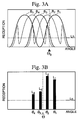
- the transceiving sensitivity to the transceived return signal of the transceiving antennas of the five transceiving channels #1 to #5, which is a result of the above-described compensation of the sensitivity of each of the transceiving channels, are shown by the curves B1 to B5 in Fig. 3A. Assuming that there is a reflecting body having an appropriate constant value of reflectivity at an arbitrary position (expressed by the direction angle) shown on the horizontal axis, the transceiving sensitivity to the transceived return signal is shown by the reception level of the reflected wave received by each transceiving channel.
- the reflected wave having the levels shown by the intersections between the vertical line shown by the dotted line extended up at this position and the respective curves B1 to B5 become the respective received signals of the channels #1 to #5.
- the angle of the position of the curves B1 to B5 from which each transceiving signal was generated cannot be distinguished.
- each of the received signals of each of the transceiving channels is treated as having been generated at the center of each of the curves B1 to B5.
- received signals of levels L1 to L4 appear respectively at center positions ⁇ 1 to ⁇ 4 of the curves B1 to B4.
- ⁇ ( ⁇ 1 L1 + ⁇ 2 L2 + ⁇ 3 L3 + ⁇ 4 L4) / (L1 + L2 + L3 + L4) is obtained.
- the position of the center of gravity ⁇ is detected as the position of the reflecting body shown in Fig. 3A.
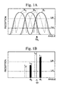
- the broken line shown in Fig. 3A and Fig. 3B is the threshold value Ln set with respect to the reception level in order to distinguish the received signals from noise, etc., and received signals having a level lower than this are eliminated.
- an appropriate threshold Lth is set in advance with respect to the level of the received signals. Additionally, in the case that this threshold serves as the reference and the level of the received signals is high, a calculation of the center of gravity is carried out using only the received signals detected by monostatic channels #1, #3, and #5.
- the standard for determining whether or not the received signals are large is considered a matter of appropriateness. For example, possible determination standards are: the levels of the received signals of one, two, or three or more of the channels exceeding this threshold value Lth, or the summation of the levels of the received signals of each transceiving channel exceeding or being a certain multiple of the threshold value.
- the reception level of any one of the transceiving channels exceeding the threshold Lth is set as the determination standard, in the example in Fig. 1A, the level of the received signal is treated as being large in the two channels #1 and #2 because the level of the received signal exceeds the threshold value Lth.
- the calculation of the center of gravity is carried out using only the received signals detected by monostatic channels #1 , #3, and #5.
- the reception level is determined to be low.
- the center of gravity is calculated using the received signals of all channels by adding bistatic channels to the monostatic channels.
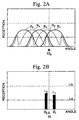
- the reception levels of the four channels #1, #2, #3, and #4 appear, but among these, the reception level of channels #3 and #4 are below the threshold value Ln, and these are treated as noise and eliminated.
- ⁇ ( ⁇ 1 L1 + ⁇ 2 L2) / (L1 + L2)
- the position of the center of gravity ⁇ calculated in this manner and shown in Fig. 2B is the closest value to the position ⁇ o of the actual reflected body shown in Fig. 2A.
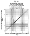
- Fig. 6 through Fig. 8 show the results of a computer simulation.
- the transceiving sensitivities B1, B3, and B5 of the monostatic channels and the transceiving sensitivities B2 and B4 of the bistatic channels having a shape identical to those shown in Fig. 3A are used.
- the direction of the reflected body shown by the triangle is moved on the horizontal axis as the target's horizontal position (deg.), and based on the reflected waves obtained in the respective cases, the direction of the reflected body calculated by the center of gravity is shown as the calculated horizontal position (deg.), where the value of half the width of the main lobe of each of the transceiving sensitivities B1 to B6 is 3°, and the reflected body is treated as a dimensionless point.
- Fig. 6 shows with a bold diagonal line the relationship between the position of the calculated center of gravity and the horizontal position of the target obtained by detecting the reflected waves using only the three monostatic channels in the case that the reception level of the reflected waves is sufficiently large.
- An ideal 45° line having a range of guaranteed precision of ⁇ 2.8° is obtained.
- Fig. 7 shows the relationship between the calculated position of the center of gravity and the target horizontal position obtained by detecting reflected waves using the three monostatic channels and the two bistatic channels in the case that the received levels of the reflected waves have values identical in size to the above case of Fig. 6. Due to the influence of side lobes in the bistatic channels, deviations from the ideal 45° line occur, and the range of guaranteed precision also becomes narrow.
- Fig. 8 shows the relationship between the position of the center of gravity using only the three monostatic channels and the target horizontal position in the case that the reception level of the reflected waves falls to about 30 dB lower then the cases in Fig. 6 and Fig. 7.
- the position of the center of gravity does not change substantially over the beam width of one channel.
- the calculated position of the center of gravity is divided over three line segments corresponding to the beam width of the three monostatic channels.
- Fig. 9 shows the relationship between the calculated center of gravity and the horizontal position of the target obtained by detecting the reflected waves using together the three monostatic channels and the two bistatic channels in the case that the reception levels of the reflected waves are set to the identical low level as in the case of Fig. 8. This takes the form of a discrete set of lines rather than a smooth curve, and the detection precision obtained is significantly higher than that of Fig. 8.
- the present invention using as an example the case of a multi-beam radar apparatus using monostatic channels and bistatic channels together was explained. However, the present invention can also be applied to a multi-beam radar apparatus using only monostatic channels.
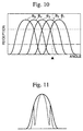
- a multi-beam radar apparatus having five monostatic channels B1 to B5 as shown in Fig. 10
- detection of the reflected waves and calculation of the center of gravity is carried out using only the three channels B1, B3, and B5 in the case that the reception level of the reflected waves is large, and detection of the reflected signals and the calculation of the center of gravity is carried out using all channels B1 to B5 in the case that the received level is small.
- Reducing the number of used channels in this manner has the advantages that the processing time necessary to detect the reflected waves and calculate the center of gravity is reduced, the detection processing is accelerated, and the tracking is increased.
- the principle of the present invention does not mean that the presence of side lobes is always necessary.
- the reason is that, as shown by the dotted line in the example of Fig. 11, the case that side lobes are present and the case that the width of the main lobe is broad, as shown by the solid line, are identical in terms of causes deterioration of detection precision.
- this is because the cause of the deterioration in the detection precision is that a reflected signal detected at the end of a lobe is treated as being present at the center of the lobe.
- the method of calculating the center of gravity was presented as an example of one method of processing the received signals from each channel.
- these methods can be replaced by other suitable methods. Examples of such methods are calculating the position of the object using the ratio in the levels of two received signals; calculating the weighted average value using a weighted coefficient taking into account the beam width in the case that the width of the beams of each channel is different; or adding preprocessing in which received signals assumed to be produced for example by noise and interference are eliminated reflecting the previous measurement results.
- an FM radar apparatus In addition, in the example the case of an FM radar apparatus was shown, but the present invention can be applied to other suitable radar apparatuses such as an AM radar apparatus that radiates AM signals and receives their reflected waves, or a pulse radar apparatus that radiates a pulse signal and receives its reflected waves.
- AM radar apparatus that radiates AM signals and receives their reflected waves
- pulse radar apparatus that radiates a pulse signal and receives its reflected waves.
- the multi-beam radar apparatus of the present invention can also be applied to other suitable types of multi-beam radar apparatuses that radiate waves such as electrical waves in other frequency bands such as the microwave band, optical light such as laser beams, and ultrasound waves, and receive their reflections.
- the multi-channel radar apparatus of the present invention is structured such that the number of used channels comprising monostatic channels and bistatic channels is increased or decreased according to the reception level of the reflected waves, and thus has the effect of being able realizing optimal detection precision.
- the number of used channels is decreased in the case that the received level is large, and thereby there are the advantages that the detection precision is increased and the tracking function is improved while at the same time the processing time is reduced.
- a multi-channel radar apparatus is provided that allows optimization of the number of used channels in terms of position detection precision and processing time reduction.
- the multi-channel apparatus according to the present invention detects the position of a body that produces reflecting waves by calculating, for example, the center of gravity using only the received signals of monostatic channels (B1, B3, and B5) when the level of the received signals is high and using the received signals of both the monostatic channels (B1, B3, and B5) and the bistatic channels (B2 and B4) when the level of the received signals is low.
Landscapes
- Engineering & Computer Science (AREA)
- Radar, Positioning & Navigation (AREA)
- Remote Sensing (AREA)
- Physics & Mathematics (AREA)
- Computer Networks & Wireless Communication (AREA)
- General Physics & Mathematics (AREA)
- Electromagnetism (AREA)
- Radar Systems Or Details Thereof (AREA)
- Measurement Of Velocity Or Position Using Acoustic Or Ultrasonic Waves (AREA)
- Optical Radar Systems And Details Thereof (AREA)
Applications Claiming Priority (2)
| Application Number | Priority Date | Filing Date | Title |
|---|---|---|---|
| JP10773399 | 1999-04-15 | ||
| JP11107733A JP2000298164A (ja) | 1999-04-15 | 1999-04-15 | マルチ・チャンネルレーダ装置 |
Publications (2)
| Publication Number | Publication Date |
|---|---|
| EP1045258A2 true EP1045258A2 (de) | 2000-10-18 |
| EP1045258A3 EP1045258A3 (de) | 2002-02-13 |
Family
ID=14466579
Family Applications (1)
| Application Number | Title | Priority Date | Filing Date |
|---|---|---|---|
| EP00108191A Withdrawn EP1045258A3 (de) | 1999-04-15 | 2000-04-13 | Mehrkanal- Radargerät |
Country Status (3)
| Country | Link |
|---|---|
| US (1) | US6522286B1 (de) |
| EP (1) | EP1045258A3 (de) |
| JP (1) | JP2000298164A (de) |
Cited By (11)
| Publication number | Priority date | Publication date | Assignee | Title |
|---|---|---|---|---|
| WO2002075355A1 (en) * | 2001-03-15 | 2002-09-26 | Fujitsu Ten Limited | Signal processing method for scanning radar |
| US6545633B1 (en) * | 2002-04-08 | 2003-04-08 | The Boeing Company | Radar system having simultaneous monostatic and bistatic mode of operation |
| EP1810054A4 (de) * | 2004-10-19 | 2011-05-18 | Univ Ohio State | Fahrzeughindernis-warnradar |
| CN103954972A (zh) * | 2014-05-21 | 2014-07-30 | 奇瑞汽车股份有限公司 | 一种多路激光雷达探测方法 |
| CN103983983A (zh) * | 2014-05-29 | 2014-08-13 | 奇瑞汽车股份有限公司 | 一种车载测距激光雷达系统 |
| CN104765035A (zh) * | 2015-03-23 | 2015-07-08 | 王方圆 | 汽车防碰撞雷达信号处理装置 |
| CN104765036A (zh) * | 2015-03-25 | 2015-07-08 | 王方圆 | 倒车雷达 |
| CN104777481A (zh) * | 2015-03-23 | 2015-07-15 | 王方圆 | 汽车防碰撞雷达系统 |
| CN104793208A (zh) * | 2015-03-25 | 2015-07-22 | 王方圆 | 抗干扰与多目标识别的汽车防撞雷达检测方法 |
| CN106338728A (zh) * | 2016-10-20 | 2017-01-18 | 加特兰微电子科技(上海)有限公司 | 雷达系统及其控制方法 |
| CN114910888A (zh) * | 2022-04-21 | 2022-08-16 | 北京一径科技有限公司 | 扫描器异常检测方法及装置、激光雷达及存储介质 |
Families Citing this family (9)
| Publication number | Priority date | Publication date | Assignee | Title |
|---|---|---|---|---|
| JP4432967B2 (ja) * | 2004-06-07 | 2010-03-17 | 三菱電機株式会社 | レーダ信号処理装置 |
| JP2006151125A (ja) * | 2004-11-26 | 2006-06-15 | Omron Corp | 車載用画像処理装置 |
| CN100412567C (zh) * | 2006-05-11 | 2008-08-20 | 哈尔滨工业大学(威海) | 一维扫描激光雷达汽车防撞系统 |
| CN102298142B (zh) * | 2011-05-16 | 2013-06-19 | 中国人民解放军海军航空工程学院 | 雷达测距模糊条件下多微弱目标ht-stc-tbd检测方法 |
| US9255988B2 (en) * | 2014-01-16 | 2016-02-09 | GM Global Technology Operations LLC | Object fusion system of multiple radar imaging sensors |
| EP3301470A3 (de) * | 2016-09-29 | 2018-06-20 | Panasonic Corporation | Multiradarsystem |
| EP3579020B1 (de) * | 2018-06-05 | 2021-03-31 | Elmos Semiconductor SE | Verfahren zur erkennung eines hindernisses mit hilfe von reflektierten ultraschallwellen |
| CN108919272A (zh) * | 2018-07-16 | 2018-11-30 | 芜湖博高光电科技股份有限公司 | 一种汽车主被动复合毫米波防撞预警系统 |
| US12153117B2 (en) * | 2022-04-05 | 2024-11-26 | Qualcomm Incorporated | Dynamic sensing configuration |
Family Cites Families (7)
| Publication number | Priority date | Publication date | Assignee | Title |
|---|---|---|---|---|
| JP3256374B2 (ja) * | 1994-05-27 | 2002-02-12 | 本田技研工業株式会社 | マルチビーム・レーダ装置 |
| JP2768439B2 (ja) * | 1994-11-08 | 1998-06-25 | 本田技研工業株式会社 | Fm−cw方式マルチビームレーダー装置 |
| JP3300558B2 (ja) * | 1994-11-10 | 2002-07-08 | 本田技研工業株式会社 | 車載用マルチ・チャネルレーダー装置 |
| JP3302848B2 (ja) * | 1994-11-17 | 2002-07-15 | 本田技研工業株式会社 | 車載レーダー装置 |
| US5933109A (en) * | 1996-05-02 | 1999-08-03 | Honda Giken Kabushiki Kaisha | Multibeam radar system |
| JP3061261B2 (ja) * | 1997-04-01 | 2000-07-10 | 本田技研工業株式会社 | Fmレーダ装置 |
| DE19714570B4 (de) * | 1997-04-09 | 2006-08-31 | Robert Bosch Gmbh | Mehrstrahliges Radarsystem |
-
1999
- 1999-04-15 JP JP11107733A patent/JP2000298164A/ja not_active Withdrawn
-
2000
- 2000-04-13 EP EP00108191A patent/EP1045258A3/de not_active Withdrawn
- 2000-04-14 US US09/549,019 patent/US6522286B1/en not_active Expired - Fee Related
Cited By (13)
| Publication number | Priority date | Publication date | Assignee | Title |
|---|---|---|---|---|
| WO2002075355A1 (en) * | 2001-03-15 | 2002-09-26 | Fujitsu Ten Limited | Signal processing method for scanning radar |
| US6900754B2 (en) | 2001-03-15 | 2005-05-31 | Fujitsu Tem Limited | Signal processing method for use with scanning radar |
| CN100359337C (zh) * | 2001-03-15 | 2008-01-02 | 富士通天株式会社 | 扫描式雷达的信号处理方法 |
| US6545633B1 (en) * | 2002-04-08 | 2003-04-08 | The Boeing Company | Radar system having simultaneous monostatic and bistatic mode of operation |
| EP1810054A4 (de) * | 2004-10-19 | 2011-05-18 | Univ Ohio State | Fahrzeughindernis-warnradar |
| CN103954972A (zh) * | 2014-05-21 | 2014-07-30 | 奇瑞汽车股份有限公司 | 一种多路激光雷达探测方法 |
| CN103983983A (zh) * | 2014-05-29 | 2014-08-13 | 奇瑞汽车股份有限公司 | 一种车载测距激光雷达系统 |
| CN104765035A (zh) * | 2015-03-23 | 2015-07-08 | 王方圆 | 汽车防碰撞雷达信号处理装置 |
| CN104777481A (zh) * | 2015-03-23 | 2015-07-15 | 王方圆 | 汽车防碰撞雷达系统 |
| CN104765036A (zh) * | 2015-03-25 | 2015-07-08 | 王方圆 | 倒车雷达 |
| CN104793208A (zh) * | 2015-03-25 | 2015-07-22 | 王方圆 | 抗干扰与多目标识别的汽车防撞雷达检测方法 |
| CN106338728A (zh) * | 2016-10-20 | 2017-01-18 | 加特兰微电子科技(上海)有限公司 | 雷达系统及其控制方法 |
| CN114910888A (zh) * | 2022-04-21 | 2022-08-16 | 北京一径科技有限公司 | 扫描器异常检测方法及装置、激光雷达及存储介质 |
Also Published As
| Publication number | Publication date |
|---|---|
| JP2000298164A (ja) | 2000-10-24 |
| US6522286B1 (en) | 2003-02-18 |
| EP1045258A3 (de) | 2002-02-13 |
Similar Documents
| Publication | Publication Date | Title |
|---|---|---|
| US6522286B1 (en) | Multi-channel radar apparatus | |
| US7132976B2 (en) | Automotive radar | |
| US6992613B2 (en) | Object detecting device | |
| US11796662B2 (en) | Radar apparatus and antenna apparatus therefor | |
| US11422254B2 (en) | Radar sensor apparatus for vehicle, object detecting method, and antenna apparatus therefor | |
| US6246359B1 (en) | Radar | |
| US7411542B2 (en) | Automotive radar system with guard beam | |
| US9285462B2 (en) | Antenna apparatus | |
| EP1239298B1 (de) | Verfahren und Radar zur Abstandsdetektion eines Zieles | |
| CN113625280B (zh) | 车辆用雷达装置、雷达装置的控制方法及车辆用雷达系统 | |
| US20220276367A1 (en) | Vehicle radar system | |
| CN103649774B (zh) | 用于机动车的角度分辨的雷达传感器 | |
| JP7188448B2 (ja) | アンテナ装置、移動体、及びターゲット判別方法 | |
| US11056766B2 (en) | Antenna apparatus | |
| US12500358B2 (en) | Antenna apparatus | |
| US20240201320A1 (en) | Method of designing radome of radar device, radome and radar device using the same | |
| JP4356820B2 (ja) | レーダ装置 | |
| JPH1027299A (ja) | 車載用レーダ装置 | |
| JP3995816B2 (ja) | レーダ装置 | |
| KR0173241B1 (ko) | 전자파와 초음파를 이용한 자동차 충돌방지장치 | |
| JP4432967B2 (ja) | レーダ信号処理装置 | |
| EP4345499A1 (de) | Zweiweg-radarstrahlmustersteuerung | |
| JP2024100013A (ja) | 車両用周囲監視装置 | |
| US20250028042A1 (en) | Vehicular radar system with multi-mode sensor having 3d antenna array | |
| JP2002156450A (ja) | 障害物識別方法 |
Legal Events
| Date | Code | Title | Description |
|---|---|---|---|
| PUAI | Public reference made under article 153(3) epc to a published international application that has entered the european phase |
Free format text: ORIGINAL CODE: 0009012 |
|
| AK | Designated contracting states |
Kind code of ref document: A2 Designated state(s): AT BE CH CY DE DK ES FI FR GB GR IE IT LI LU MC NL PT SE Kind code of ref document: A2 Designated state(s): DE FR GB |
|
| AX | Request for extension of the european patent |
Free format text: AL;LT;LV;MK;RO;SI |
|
| PUAL | Search report despatched |
Free format text: ORIGINAL CODE: 0009013 |
|
| AK | Designated contracting states |
Kind code of ref document: A3 Designated state(s): AT BE CH CY DE DK ES FI FR GB GR IE IT LI LU MC NL PT SE |
|
| AX | Request for extension of the european patent |
Free format text: AL;LT;LV;MK;RO;SI |
|
| RIC1 | Information provided on ipc code assigned before grant |
Free format text: 7G 01S 13/93 A, 7G 01S 7/35 B, 7G 01S 13/42 B, 7G 01S 13/00 B, 7G 01S 13/87 B |
|
| 17P | Request for examination filed |
Effective date: 20020313 |
|
| AKX | Designation fees paid |
Free format text: DE FR GB |
|
| 17Q | First examination report despatched |
Effective date: 20061106 |
|
| GRAP | Despatch of communication of intention to grant a patent |
Free format text: ORIGINAL CODE: EPIDOSNIGR1 |
|
| STAA | Information on the status of an ep patent application or granted ep patent |
Free format text: STATUS: THE APPLICATION IS DEEMED TO BE WITHDRAWN |
|
| 18D | Application deemed to be withdrawn |
Effective date: 20100427 |