EP1045971B1 - Echangeur de chaleur en materiau composite et procede pour sa fabrication - Google Patents
Echangeur de chaleur en materiau composite et procede pour sa fabrication Download PDFInfo
- Publication number
- EP1045971B1 EP1045971B1 EP99954068A EP99954068A EP1045971B1 EP 1045971 B1 EP1045971 B1 EP 1045971B1 EP 99954068 A EP99954068 A EP 99954068A EP 99954068 A EP99954068 A EP 99954068A EP 1045971 B1 EP1045971 B1 EP 1045971B1
- Authority
- EP
- European Patent Office
- Prior art keywords
- composite material
- heat exchanger
- intermediate portion
- fluid circulation
- circulation channels
- Prior art date
- Legal status (The legal status is an assumption and is not a legal conclusion. Google has not performed a legal analysis and makes no representation as to the accuracy of the status listed.)
- Expired - Lifetime
Links
- 239000002131 composite material Substances 0.000 title claims abstract description 66
- 238000000034 method Methods 0.000 title claims description 14
- 239000012530 fluid Substances 0.000 claims abstract description 24
- 238000005219 brazing Methods 0.000 claims abstract description 17
- 239000011159 matrix material Substances 0.000 claims abstract description 14
- 238000002485 combustion reaction Methods 0.000 claims abstract description 8
- 239000011204 carbon fibre-reinforced silicon carbide Substances 0.000 claims abstract 2
- 239000000463 material Substances 0.000 claims description 22
- 229910052751 metal Inorganic materials 0.000 claims description 20
- 239000002184 metal Substances 0.000 claims description 20
- 239000011248 coating agent Substances 0.000 claims description 16
- 238000000576 coating method Methods 0.000 claims description 16
- 239000000835 fiber Substances 0.000 claims description 14
- 230000002787 reinforcement Effects 0.000 claims description 14
- 238000004519 manufacturing process Methods 0.000 claims description 8
- 238000003754 machining Methods 0.000 claims description 4
- 239000011153 ceramic matrix composite Substances 0.000 claims description 3
- 238000000151 deposition Methods 0.000 claims description 2
- 239000000956 alloy Substances 0.000 claims 1
- 229910045601 alloy Inorganic materials 0.000 claims 1
- 239000000919 ceramic Substances 0.000 abstract description 6
- 230000004927 fusion Effects 0.000 abstract description 4
- 230000004907 flux Effects 0.000 abstract description 2
- HBMJWWWQQXIZIP-UHFFFAOYSA-N silicon carbide Chemical compound [Si+]#[C-] HBMJWWWQQXIZIP-UHFFFAOYSA-N 0.000 description 12
- 229910010271 silicon carbide Inorganic materials 0.000 description 12
- 229910052799 carbon Inorganic materials 0.000 description 11
- OKTJSMMVPCPJKN-UHFFFAOYSA-N Carbon Chemical compound [C] OKTJSMMVPCPJKN-UHFFFAOYSA-N 0.000 description 9
- 229910000679 solder Inorganic materials 0.000 description 7
- 238000007789 sealing Methods 0.000 description 6
- 230000015572 biosynthetic process Effects 0.000 description 5
- 229920000049 Carbon (fiber) Polymers 0.000 description 4
- 239000004917 carbon fiber Substances 0.000 description 4
- 150000002739 metals Chemical class 0.000 description 4
- 239000012808 vapor phase Substances 0.000 description 3
- RYGMFSIKBFXOCR-UHFFFAOYSA-N Copper Chemical compound [Cu] RYGMFSIKBFXOCR-UHFFFAOYSA-N 0.000 description 2
- 229910052802 copper Inorganic materials 0.000 description 2
- 239000010949 copper Substances 0.000 description 2
- 238000000280 densification Methods 0.000 description 2
- 239000000446 fuel Substances 0.000 description 2
- VNWKTOKETHGBQD-UHFFFAOYSA-N methane Chemical compound C VNWKTOKETHGBQD-UHFFFAOYSA-N 0.000 description 2
- 239000002243 precursor Substances 0.000 description 2
- 239000000126 substance Substances 0.000 description 2
- 230000009466 transformation Effects 0.000 description 2
- 238000004804 winding Methods 0.000 description 2
- VYZAMTAEIAYCRO-UHFFFAOYSA-N Chromium Chemical compound [Cr] VYZAMTAEIAYCRO-UHFFFAOYSA-N 0.000 description 1
- XUIMIQQOPSSXEZ-UHFFFAOYSA-N Silicon Chemical compound [Si] XUIMIQQOPSSXEZ-UHFFFAOYSA-N 0.000 description 1
- RTAQQCXQSZGOHL-UHFFFAOYSA-N Titanium Chemical compound [Ti] RTAQQCXQSZGOHL-UHFFFAOYSA-N 0.000 description 1
- QCWXUUIWCKQGHC-UHFFFAOYSA-N Zirconium Chemical compound [Zr] QCWXUUIWCKQGHC-UHFFFAOYSA-N 0.000 description 1
- 230000008901 benefit Effects 0.000 description 1
- 229910052790 beryllium Inorganic materials 0.000 description 1
- ATBAMAFKBVZNFJ-UHFFFAOYSA-N beryllium atom Chemical compound [Be] ATBAMAFKBVZNFJ-UHFFFAOYSA-N 0.000 description 1
- 238000005234 chemical deposition Methods 0.000 description 1
- 239000000470 constituent Substances 0.000 description 1
- 238000010276 construction Methods 0.000 description 1
- 239000002826 coolant Substances 0.000 description 1
- 239000004744 fabric Substances 0.000 description 1
- 229910052735 hafnium Inorganic materials 0.000 description 1
- VBJZVLUMGGDVMO-UHFFFAOYSA-N hafnium atom Chemical compound [Hf] VBJZVLUMGGDVMO-UHFFFAOYSA-N 0.000 description 1
- 239000013529 heat transfer fluid Substances 0.000 description 1
- 238000005470 impregnation Methods 0.000 description 1
- 230000008595 infiltration Effects 0.000 description 1
- 238000001764 infiltration Methods 0.000 description 1
- 238000005304 joining Methods 0.000 description 1
- 239000007788 liquid Substances 0.000 description 1
- 229910001092 metal group alloy Inorganic materials 0.000 description 1
- 230000001590 oxidative effect Effects 0.000 description 1
- 230000008569 process Effects 0.000 description 1
- 239000011214 refractory ceramic Substances 0.000 description 1
- 229910052710 silicon Inorganic materials 0.000 description 1
- 239000010703 silicon Substances 0.000 description 1
- 238000005476 soldering Methods 0.000 description 1
- 239000000758 substrate Substances 0.000 description 1
- 239000010936 titanium Substances 0.000 description 1
- 229910052719 titanium Inorganic materials 0.000 description 1
- 229910052726 zirconium Inorganic materials 0.000 description 1
Images

Classifications
-
- F—MECHANICAL ENGINEERING; LIGHTING; HEATING; WEAPONS; BLASTING
- F02—COMBUSTION ENGINES; HOT-GAS OR COMBUSTION-PRODUCT ENGINE PLANTS
- F02K—JET-PROPULSION PLANTS
- F02K1/00—Plants characterised by the form or arrangement of the jet pipe or nozzle; Jet pipes or nozzles peculiar thereto
- F02K1/78—Other construction of jet pipes
- F02K1/82—Jet pipe walls, e.g. liners
- F02K1/822—Heat insulating structures or liners, cooling arrangements, e.g. post combustion liners; Infrared radiation suppressors
-
- F—MECHANICAL ENGINEERING; LIGHTING; HEATING; WEAPONS; BLASTING
- F23—COMBUSTION APPARATUS; COMBUSTION PROCESSES
- F23R—GENERATING COMBUSTION PRODUCTS OF HIGH PRESSURE OR HIGH VELOCITY, e.g. GAS-TURBINE COMBUSTION CHAMBERS
- F23R3/00—Continuous combustion chambers using liquid or gaseous fuel
-
- F—MECHANICAL ENGINEERING; LIGHTING; HEATING; WEAPONS; BLASTING
- F23—COMBUSTION APPARATUS; COMBUSTION PROCESSES
- F23R—GENERATING COMBUSTION PRODUCTS OF HIGH PRESSURE OR HIGH VELOCITY, e.g. GAS-TURBINE COMBUSTION CHAMBERS
- F23R3/00—Continuous combustion chambers using liquid or gaseous fuel
- F23R3/005—Combined with pressure or heat exchangers
-
- F—MECHANICAL ENGINEERING; LIGHTING; HEATING; WEAPONS; BLASTING
- F23—COMBUSTION APPARATUS; COMBUSTION PROCESSES
- F23R—GENERATING COMBUSTION PRODUCTS OF HIGH PRESSURE OR HIGH VELOCITY, e.g. GAS-TURBINE COMBUSTION CHAMBERS
- F23R3/00—Continuous combustion chambers using liquid or gaseous fuel
- F23R3/007—Continuous combustion chambers using liquid or gaseous fuel constructed mainly of ceramic components
-
- Y—GENERAL TAGGING OF NEW TECHNOLOGICAL DEVELOPMENTS; GENERAL TAGGING OF CROSS-SECTIONAL TECHNOLOGIES SPANNING OVER SEVERAL SECTIONS OF THE IPC; TECHNICAL SUBJECTS COVERED BY FORMER USPC CROSS-REFERENCE ART COLLECTIONS [XRACs] AND DIGESTS
- Y02—TECHNOLOGIES OR APPLICATIONS FOR MITIGATION OR ADAPTATION AGAINST CLIMATE CHANGE
- Y02E—REDUCTION OF GREENHOUSE GAS [GHG] EMISSIONS, RELATED TO ENERGY GENERATION, TRANSMISSION OR DISTRIBUTION
- Y02E30/00—Energy generation of nuclear origin
- Y02E30/10—Nuclear fusion reactors
-
- Y—GENERAL TAGGING OF NEW TECHNOLOGICAL DEVELOPMENTS; GENERAL TAGGING OF CROSS-SECTIONAL TECHNOLOGIES SPANNING OVER SEVERAL SECTIONS OF THE IPC; TECHNICAL SUBJECTS COVERED BY FORMER USPC CROSS-REFERENCE ART COLLECTIONS [XRACs] AND DIGESTS
- Y02—TECHNOLOGIES OR APPLICATIONS FOR MITIGATION OR ADAPTATION AGAINST CLIMATE CHANGE
- Y02T—CLIMATE CHANGE MITIGATION TECHNOLOGIES RELATED TO TRANSPORTATION
- Y02T50/00—Aeronautics or air transport
- Y02T50/60—Efficient propulsion technologies, e.g. for aircraft
-
- Y—GENERAL TAGGING OF NEW TECHNOLOGICAL DEVELOPMENTS; GENERAL TAGGING OF CROSS-SECTIONAL TECHNOLOGIES SPANNING OVER SEVERAL SECTIONS OF THE IPC; TECHNICAL SUBJECTS COVERED BY FORMER USPC CROSS-REFERENCE ART COLLECTIONS [XRACs] AND DIGESTS
- Y10—TECHNICAL SUBJECTS COVERED BY FORMER USPC
- Y10T—TECHNICAL SUBJECTS COVERED BY FORMER US CLASSIFICATION
- Y10T428/00—Stock material or miscellaneous articles
- Y10T428/24—Structurally defined web or sheet [e.g., overall dimension, etc.]
- Y10T428/24149—Honeycomb-like
-
- Y—GENERAL TAGGING OF NEW TECHNOLOGICAL DEVELOPMENTS; GENERAL TAGGING OF CROSS-SECTIONAL TECHNOLOGIES SPANNING OVER SEVERAL SECTIONS OF THE IPC; TECHNICAL SUBJECTS COVERED BY FORMER USPC CROSS-REFERENCE ART COLLECTIONS [XRACs] AND DIGESTS
- Y10—TECHNICAL SUBJECTS COVERED BY FORMER USPC
- Y10T—TECHNICAL SUBJECTS COVERED BY FORMER US CLASSIFICATION
- Y10T428/00—Stock material or miscellaneous articles
- Y10T428/30—Self-sustaining carbon mass or layer with impregnant or other layer
Definitions
- the invention relates to heat exchangers that use thermal exchange sets based on a circulation of fluid, and which are intended to be used in an environment thermally severe.
- the material transformation systems for example nuclear fusion reactors, and propulsion systems, particular the reactor combustion chamber wall elements, in particular ramjets.
- the heat exchangers used in these applications are generally metallic, at least in part. But the properties thermal and mechanical properties of metals and metal alloys limit their field of use, as well as performance and security. Moreover, the metal heat exchangers are heavy and bulky, which penalizes their use at least in some applications.
- the object of the invention is to provide a heat exchanger able to be used in a severe thermal environment.
- the invention also aims to provide a heat exchanger heat in which the realization of different thermal functions and structural aspects can be optimized to reduce as much as possible the mass, clutter and cost.
- the invention also aims to provide a heat exchanger heat that can be easily achieved.
- the subject of the invention is also a method of manufacturing a such heat exchanger.
- a heat exchanger according to the invention is characterized in that it comprises an intermediate part made of composite material refractory in which fluid circulation channels are formed, the intermediate portion being interposed between a material part refractory composite forming a heat shield and a material part thermostructural composite forming a structure for holding the exchanger, the constituent parts of the heat exchanger being assembled by brazing.
- thermostructural composite material is a material composite having mechanical properties making it suitable for constitute structural elements and which retain these properties up to high temperatures.
- Composite materials thermostructures are typically composite materials having a fibrous reinforcement of refractory fibers, such as carbon fibers or ceramic, densified by a refractory matrix, such as a matrix carbon or ceramic.
- Examples of composite materials thermostructural are the composite materials carbon / carbon (C / C) reinforcement fibers and carbon matrix, and the composite materials to ceramic matrix (CMC), for example with a silicon carbide matrix (SiC).
- thermostructural composite material forming the holding structure of the exchanger is a composite material CC. It can be in the form of a honeycomb or a material composite in which the fibrous reinforcement is formed of fibrous layers superimposed interconnected by transversely extending fibers compared to the layers, as can be obtained by needling, as described for example in US Pat. No. 4,790,052.
- the material of the intermediate part is also a C / C composite material which is then used more for its refractory and structural qualities.
- the material of the forming part thermal screen is a CMC type material, for example a material composite C / SiC or SiC / SiC (carbon fiber or carbide reinforcement of silicon densified by a silicon carbide matrix), more suitable that composite materials C / C to be exposed to a heat flow intense especially in oxidizing atmosphere.
- An advantage of the exchanger of heat according to the invention lies in the possibility of selecting the the most suitable materials to ensure thermal functions and the heat exchanger, thus optimizing the construction of the exchanger terms of performance and size.
- the fluid circulation channels are formed by example by machining, in a face of the intermediate piece and are delimited in part by the adjacent wall of one of the other two parts.
- the realization of fluid circulation channels is therefore particularly simple.
- the watertightness of the channels can be ensured by forming a coating on their wall, for example a coating metal in a thin layer.
- a coating can be formed on the all the faces facing the parts to be assembled in order to facilitate the brazing also constituting a bonding layer for the solder.
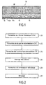
- FIG. 1 is a sectional view of a unitary block 10 constituting a heat exchanger element.
- Block 10 can constitute a wall element of an enclosure where thermal conditions prevail severe, for example a wall element of a containment chamber of plasma in a nuclear fusion reactor.
- the heat exchanger block 10 includes a heat shield 12, the outer face 12 a is to be exposed to a heat flux, an intermediate portion 14 having channels 16 for circulation of fluid and a support structure 18.
- the intermediate portion is interposed between the heat shield 12 and the holding structure 18 and is bonded thereto by brazing.
- the fluid circulation channels 16 are machined in the face of the intermediate portion located on the side of the heat shield 12 and covered by the inner face 12 b of the heat shield, which inner face 12 b thus partially delimits the channels 16
- the channels 16 are intended to be connected to a circulation circuit of a heat transfer fluid.
- the heat shield 12 exposed to the thermal conditions more severe is made of a refractory composite material, preferably a ceramic matrix composite material (CMC), for example a material C / SiC type composite with fiber reinforcement in densified carbon fiber by a silicon carbide matrix.
- CMC ceramic matrix composite material
- the intermediate part is also a composite material refractory, for example a C / C composite material with fiber reinforcement in carbon fibers densified by a carbon matrix.
- the holding structure is made of a thermostructural composite material and is performed to provide the structural function of the block 10.
- a support structure in the form of honeycomb structure of composite material C / C A method of manufacture of such a structure is described in US Patent 5,415,715.
- the layers are for example layers of fabric, unidirectional layers superimposed with different directions, layers of felt ..., and they are of preferably bonded together by needling.
- a manufacturing process of such a C / C composite material is described in US Patent 4,790,052.
- Figure 2 shows the steps of a manufacturing process of block 10 of heat exchanger.
- the heat shield made of CMC material, for example material composite material C / SiC, the intermediate part made of composite material C / C and the holding structure made of composite material C / C are produced separately (steps 20, 22, 24).
- the processes for manufacturing parts in composite material type C / C or C / SiC by developing a reinforcement fibrous, or preform, and densification of the fibrous reinforcement by a matrix are well known. Densification can be achieved by infiltration chemical vapor phase, or by impregnation with a precursor of the matrix in the liquid state and transformation of the precursor by treatment thermal.
- Channels 16 are machined in one side of the part intermediate 14 (step 26).
- a metal coating can be formed on the entirety of the faces opposite the intermediate part, the screen thermal and holding structure (step 28).
- the coating metal is chosen to improve the wettability with respect to the solder used then for assembling the different parts and thus favoring the attachment of the solder.
- the metal coating also ensures the sealing of the walls of the fluid circulation channels. Indeed, composite materials C / C or CMC materials obtained as indicated above inevitably have a residual porosity that it should be sealed at the surface to seal the channels.
- the metal coating for example titanium, chrome, zirconium, hafnium or beryllium can be deposited by chemical deposition vapor phase or by vacuum projection.
- a metallic clinging coating of the brazing is not necessary, it is nevertheless necessary to ensure the tightness of the walls of the channels 16.
- This sealing is then ensured by deposit a sealing layer, at least on the machined portions of the portion intermediate and on the portions of the adjacent face of the heat shield located opposite.
- the sealing layer is deposited by deposit chemical vapor phase. It is metallic or non-metallic, by example in carbon or ceramic.
- Soldering is carried out by depositing a layer of solder on the faces to be assembled from the middle part of the screen thermal and holding structure and wearing the whole, maintained in a tool, at the desired brazing temperature given the solder used.
- the solder used is chosen from those known for brazing refractory ceramics or composites between them or on metals, for example the solders marketed under the names "TiCuSil” or "Cu-ABA” by the United States Society of America Wesgo, Inc. Reference may be made to the patent application WO 98/03 297 cited above, as well as an article by A.G. Foley and D.J. Andrews GEC ALSTHOM "Active metal brazing for joining ceramics to metals" TECHNICAL REVIEW, No. 13, February 1994, France, p. 49-64.
- FIG 3 illustrates in an exploded fashion another way of embodiment of a heat exchanger according to the invention constituting a reactor chamber element 30.
- the heat shield 32 is an annular axisymmetric piece having a front portion cylindrical extended to the rear by a frustoconical portion.
- the screen thermal 32 is made of a single piece of CMC composite material, for example in C / SiC composite material.
- the fibrous reinforcement of the material composite is made by winding a fibrous texture on a shaped mandrel, and the preform obtained is densified by the matrix of the composite material.
- the fluid circulation channels 36 are formed in the axial direction by machining the face of an intermediate portion 34 located opposite the heat shield 32.
- the intermediate portion 34 is made of composite material C / C.
- the coolant is a fuel that is heated by passing through the heat exchanger before being injected into the combustion chamber.
- Inlet and outlet ports 33 a, 33 b of the fluid are formed through the heat shield 32 in the vicinity of its axial ends, and at the grooves, such as 37 machined circumferentially in the front and the back of the intermediate portion to distribute the fluid in the channels 36 at one end, and collect at the other end of the channels.
- the intermediate portion 34 is integral with a structure of holding 38 in the form of annular structure made of composite material CC. It is formed by winding a layered fibrous texture superimposed on a mandrel and connecting the layers together by means of fibers extending transversely to the layers, for example by needling, the annular preform obtained being densified by a carbon matrix.
- An embodiment of annular preforms needles to form structural reinforcements in composite material C / C is described in US Pat. No. 4,790,052 already cited.
- the holding structure 38 and the intermediate part can be made in two parts assembled by brazing or, as in the illustrated example. in one part.
- the heat shield 32 is brazed on the face of the part intermediate having channels 36 and grooves 37.
- Brazing is carried out as described above with reference in FIGS. 1 and 2, possibly after coating formation brazing metal, at least after formation of a sealing coating on the walls of the channels 36 and grooves 37.
- Figure 4 illustrates very schematically a structure of ramjet whose wall 40 constitutes a heat exchanger according to the invention.
- the wall 40 has a structure similar to that of the block 10 of the Figure 1 and is similarly manufactured.
- the heat shield 42 located the inner side of the wall is made of CMC material, for example C / SiC. It is brazed on an intermediate portion 44 in a face of which are machined channels 46, the face of the intermediate portion 44 the channels being covered by the heat shield 42. channels 46 are traversed by a fluid constituting an injected fuel in the firebox after being warmed up by passing in the wall 40.
- the intermediate portion 44 is made of composite material C / C and is brazed to a support structure 48 also made of material composite C / C.
- the holding structure is advantageously shaped honeycomb to lighten up the whole.
Landscapes
- Engineering & Computer Science (AREA)
- Chemical & Material Sciences (AREA)
- Combustion & Propulsion (AREA)
- Mechanical Engineering (AREA)
- General Engineering & Computer Science (AREA)
- Ceramic Engineering (AREA)
- Ceramic Products (AREA)
- Heat-Exchange Devices With Radiators And Conduit Assemblies (AREA)
- Separation By Low-Temperature Treatments (AREA)
- Compositions Of Oxide Ceramics (AREA)
- Moulding By Coating Moulds (AREA)
- Manufacture Of Alloys Or Alloy Compounds (AREA)
Description
Voir aussi le document US-A-5 174 368.
- la figure 1 illustre en coupe un élément d'échangeur de chaleur selon un premier mode de réalisation de l'invention ;
- la figure 2 montre les étapes d'un procédé de réalisation de l'élément d'échangeur de chaleur de la figure 1 ;
- la figure 3 illustre de façon éclatée un élément de chambre de combustion de réacteur formant échangeur de chaleur selon un deuxième mode de réalisation de l'invention ; et
- la figure 4 illustre très schématiquement une chambre de statoréacteur avec une vue de détail d'un élément de paroi de la chambre de combustion formant échangeur de chaleur selon un troisième mode de réalisation de l'invention.
Claims (21)
- Echangeur de chaleur en matériau composite, caractérisé en ce qu'il comprend une partie intermédiaire (14 ; 34 ; 44) en matériau composite réfractaire dans laquelle sont formés des canaux de circulation de fluide (16 ; 36 ; 46), la partie intermédiaire étant intercalée entre une partie en matériau composite réfractaire formant écran thermique (12 ; 32 ; 42) et une partie en matériau composite thermostructural formant structure de maintien de l'échangeur (18 ; 38 ; 48), les parties constitutives de l'échangeur de chaleur étant assemblées par brasage.
- Echangeur de chaleur selon la revendication 1, caractérisé en ce que la partie intermédiaire (14 ; 34 ; 44) est en matériau composite C/C.
- Echangeur de chaleur selon l'une quelconque des revendications 1 et 2, caractérisé en ce que la partie formant écran thermique (12 ; 32 ; 42) est en matériau composite à matrice céramique.
- Echangeur de chaleur selon la revendication 3, caractérisé en ce que la partie formant écran thermique (12 ; 32 ; 42) est en matériau composite C/SiC.
- Echangeur de chaleur selon l'une quelconque des revendications 1 à 4, caractérisé en ce que la partie formant structure de maintien (18 ; 38 : 48) est en matériau composite C/C.
- Echangeur de chaleur selon l'une quelconque des revendications 1 à 5, caractérisé en ce que les canaux de circulation de fluide (16 ; 36 ; 46) sont formés dans une face de la partie intermédiaire (14 ; 34 ; 44) et sont délimités en partie par la paroi adjacente d'une des deux autres parties.
- Echangeur de chaleur selon l'une quelconque des revendications 1 à 6, caractérisé en ce que les canaux de circulation de fluide (16 ; 36 ; 46) sont munis d'un revêtement étanche.
- Echangeur de chaleur selon l'une quelconque des revendications 1 à 7, caractérisé en ce que la partie formant structure de maintien est en nid d'abeilles.
- Echangeur de chaleur selon l'une quelconque des revendications 1 à 7, caractérisé en ce que la partie formant structure de maintien (18 ; 38 : 48) est en un matériau composite comprenant un renfort fibreux ayant plusieurs couches fibreuses superposées liées entre elles par des fibres s'étendant transversalement par rapport aux couches.
- Elément (30 ; 40) de paroi de chambre de combustion de stato réacteur, caractérisé en ce qu'il incorpore un échangeur de chaleur selon l'une quelconque des revendications 1 à 8.
- Procédé de fabrication d'un échangeur de chaleur en matériau composite, caractérisé en ce qu'il comprendla réalisation d'une partie intermédiaire en matériau composite réfractaire munie de canaux de circulation de fluide,la réalisation d'une partie d'écran thermique en matériau composite réfractaire,la réalisation d'une partie de structure en matériau composite thermostructural, etl'assemblage des différentes parties par brasage en interposant la partie intermédiaire entre la partie d'écran thermique et la partie de structure.
- Procédé selon la revendication 11, caractérisé en ce que les canaux de circulation de fluide sont formés par usinage dans une face de la partie intermédiaire.
- Procédé selon l'une quelconque des revendications 11 et 12, caractérisé en ce que l'on réalise la partie intermédiaire en matériau composite C/C.
- Procédé selon l'une quelconque des revendications 11 à 13, caractérisé en ce que l'on forme un revêtement étanche sur les parois des canaux de circulation de fluide.
- Procédé selon la revendication 14, caractérisé en ce que le revêtement étanche est formé par dépôt d'une couche métallique.
- Procédé selon l'une quelconque des revendications 11 à 15, caractérisé en ce que l'on réalise la partie d'écran thermique en matériau composite à matrice céramique.
- Procédé selon l'une quelconque des revendications 11 à 16, caractérisé en ce que l'on réalise la partie de structure en matériau composite C/C.
- Procédé selon l'une quelconque des revendications 11 à 17, caractérisé en ce que l'on réalise la partie de structure en nid d'abeilles.
- Procédé selon l'une quelconque des revendications 11 à 17, caractérisé en ce que l'on réalise la partie de structure en un matériau composite ayant un renfort fibreux densifié par une matrice, et en ce que le renfort fibreux est réalisé par superposition et aiguilletage de plusieurs couches fibreuses.
- Procédé selon l'une quelconque des revendications 11 à 19, caractérisé en ce que l'on forme une couche métallique d'accrochage de brasure sur les faces en regard des parties à assembler par brasage.
- Procédé selon la revendication 20, caractérisé en ce que les canaux de circulation de fluide sont formés par usinage dans une face de la partie intermédiaire qui est recouverte par une face adjacente d'une autre partie, et la couche métallique est formée sur la face de la partie intermédiaire, après usinage des canaux, et sur la face adjacente, de sorte que la couche métallique constitue également un revêtement étanche des parois des canaux de circulation de fluide.
Applications Claiming Priority (3)
| Application Number | Priority Date | Filing Date | Title |
|---|---|---|---|
| FR9813923A FR2785664B1 (fr) | 1998-11-05 | 1998-11-05 | Echangeur de chaleur en materiau composite et procede pour sa fabrication |
| FR9813923 | 1998-11-05 | ||
| PCT/FR1999/002708 WO2000028202A1 (fr) | 1998-11-05 | 1999-11-05 | Echangeur de chaleur en materiau composite et procede pour sa fabrication |
Publications (2)
| Publication Number | Publication Date |
|---|---|
| EP1045971A1 EP1045971A1 (fr) | 2000-10-25 |
| EP1045971B1 true EP1045971B1 (fr) | 2004-04-07 |
Family
ID=9532395
Family Applications (1)
| Application Number | Title | Priority Date | Filing Date |
|---|---|---|---|
| EP99954068A Expired - Lifetime EP1045971B1 (fr) | 1998-11-05 | 1999-11-05 | Echangeur de chaleur en materiau composite et procede pour sa fabrication |
Country Status (14)
| Country | Link |
|---|---|
| US (1) | US6397581B1 (fr) |
| EP (1) | EP1045971B1 (fr) |
| JP (1) | JP4249396B2 (fr) |
| KR (1) | KR100613827B1 (fr) |
| CN (1) | CN1113164C (fr) |
| AT (1) | ATE263916T1 (fr) |
| CA (1) | CA2317707C (fr) |
| DE (1) | DE69916240T2 (fr) |
| FR (1) | FR2785664B1 (fr) |
| IL (1) | IL137097A (fr) |
| NO (1) | NO323992B1 (fr) |
| RU (1) | RU2249166C2 (fr) |
| UA (1) | UA55499C2 (fr) |
| WO (1) | WO2000028202A1 (fr) |
Families Citing this family (38)
| Publication number | Priority date | Publication date | Assignee | Title |
|---|---|---|---|---|
| US6800828B2 (en) * | 2001-03-31 | 2004-10-05 | Honeywell International Inc. | Electrical discharge machining of carbon-containing work pieces |
| AT5079U1 (de) | 2001-04-30 | 2002-03-25 | Plansee Ag | Verfahren zum fügen eines hochtemperaturwerkstoff-bauteilverbundes |
| US6907920B2 (en) * | 2002-01-29 | 2005-06-21 | United Technologies Corporation | Heat exchanger panel |
| US6715293B2 (en) * | 2002-03-28 | 2004-04-06 | United Technologies Corporation | Scram jet engine design |
| FR2840974B1 (fr) * | 2002-06-13 | 2005-12-30 | Snecma Propulsion Solide | Anneau d'etancheite pour cahmbre de combustion et chambre de combustion comportant un tel anneau |
| FR2850742B1 (fr) * | 2003-01-30 | 2005-09-23 | Snecma Propulsion Solide | Panneau de refroidissement actif en materiau composite thermostructural et procede pour sa fabrication |
| FR2850741B1 (fr) * | 2003-01-30 | 2005-09-23 | Snecma Propulsion Solide | Procede de fabrication d'un panneau de refroidissement actif en materiau composite thermostructural |
| KR20050004524A (ko) * | 2003-07-02 | 2005-01-12 | 최동민 | 연소장치 |
| FR2871847B1 (fr) * | 2004-06-17 | 2006-09-29 | Snecma Moteurs Sa | Montage d'un distributeur de turbine sur une chambre de combustion a parois en cmc dans une turbine a gaz |
| FR2872072B1 (fr) * | 2004-06-24 | 2006-09-29 | Snecma Propulsion Solide Sa | Procede de brasage de pieces en materiau composite thermostructural siliciure |
| EP1672281A1 (fr) * | 2004-12-16 | 2006-06-21 | Siemens Aktiengesellschaft | Elément de protection thermique |
| US7431074B1 (en) | 2006-03-20 | 2008-10-07 | Fellman Michael L | Radiator structure |
| DE102006021539A1 (de) * | 2006-05-08 | 2007-11-15 | Eads Space Transportation Gmbh | Verfahren zur Herstellung von Bauteilen für den Raketenbau |
| JP5029257B2 (ja) * | 2007-01-17 | 2012-09-19 | 東京エレクトロン株式会社 | 載置台構造及び処理装置 |
| US8127555B2 (en) * | 2007-12-13 | 2012-03-06 | Pratt & Whitney Rocketdyne, Inc. | Flowpath heat exchanger for thermal management and power generation within a hypersonic vehicle |
| US7914904B2 (en) * | 2008-03-25 | 2011-03-29 | General Electric Company | Component in a combustion system, and process for preventing slag, ash, and char buildup |
| DE102010032612A1 (de) * | 2010-07-28 | 2012-03-29 | Martin GmbH für Umwelt- und Energietechnik | Verfahren zum Schutz von Wärmetauscherrohren in Dampfkesselanlagen, Formkörper, Wärmetauscherrohr und Dampfkesselanlage |
| JP5769519B2 (ja) * | 2011-06-30 | 2015-08-26 | コバレントマテリアル株式会社 | 強化用繊維材料と強化用繊維材料を用いた繊維強化セラミックス複合材料及びこれらの製造方法 |
| CN102784987B (zh) * | 2012-06-18 | 2014-11-19 | 航天材料及工艺研究所 | 一种C/C复合材料内置Ni基高温合金管的焊接方法 |
| FR3001409B1 (fr) * | 2013-01-29 | 2015-07-03 | Herakles | Procede de fabrication d'une structure alveolaire de forme courbee en materiau composite |
| US9018511B2 (en) | 2013-03-08 | 2015-04-28 | Hamilton Sundstrand Space Systems International, Inc. | Spring-loaded heat exchanger fins |
| US9624786B2 (en) | 2013-03-15 | 2017-04-18 | Rolls-Royce Corporation | Braze materials and method for joining of ceramic matrix composites |
| US10598378B2 (en) * | 2013-10-07 | 2020-03-24 | United Technologies Corporation | Bonded combustor wall for a turbine engine |
| JP2016142484A (ja) * | 2015-02-03 | 2016-08-08 | イビデン株式会社 | 準カプセル溶融塩蓄熱材 |
| US10520193B2 (en) * | 2015-10-28 | 2019-12-31 | General Electric Company | Cooling patch for hot gas path components |
| US10947162B2 (en) | 2017-04-13 | 2021-03-16 | Rolls-Royce Corporation | Braze alloys for joining or repairing ceramic matrix composite (CMC) components |
| CN108644028B (zh) * | 2018-03-12 | 2020-01-24 | 上海卫星工程研究所 | 一种大推力双向摇摆轨控发动机高温隔热屏 |
| CN109336630B (zh) * | 2018-08-29 | 2021-06-11 | 宁波华源精特金属制品有限公司 | 一种支架及其制备方法 |
| GB2595744B (en) * | 2020-06-01 | 2022-11-16 | Desmond Lewis Stephen | Reduced velocity ramjet |
| US11460191B2 (en) | 2020-08-31 | 2022-10-04 | General Electric Company | Cooling insert for a turbomachine |
| US11614233B2 (en) | 2020-08-31 | 2023-03-28 | General Electric Company | Impingement panel support structure and method of manufacture |
| US11994293B2 (en) | 2020-08-31 | 2024-05-28 | General Electric Company | Impingement cooling apparatus support structure and method of manufacture |
| US11994292B2 (en) | 2020-08-31 | 2024-05-28 | General Electric Company | Impingement cooling apparatus for turbomachine |
| US11371702B2 (en) | 2020-08-31 | 2022-06-28 | General Electric Company | Impingement panel for a turbomachine |
| US11255545B1 (en) | 2020-10-26 | 2022-02-22 | General Electric Company | Integrated combustion nozzle having a unified head end |
| JPWO2022230846A1 (fr) * | 2021-04-28 | 2022-11-03 | ||
| US11767766B1 (en) | 2022-07-29 | 2023-09-26 | General Electric Company | Turbomachine airfoil having impingement cooling passages |
| FR3146880A1 (fr) * | 2023-03-20 | 2024-09-27 | Airbus Operations (S.A.S.) | Ensemble de propulsion comprenant un système de conditionnement de carburant positionné à l’arrière d’une zone d’éjection de débris, aéronef comprenant au moins un tel ensemble de propulsion |
Family Cites Families (10)
| Publication number | Priority date | Publication date | Assignee | Title |
|---|---|---|---|---|
| US4488920A (en) * | 1982-05-18 | 1984-12-18 | Williams International Corporation | Process of making a ceramic heat exchanger element |
| US4838031A (en) * | 1987-08-06 | 1989-06-13 | Avco Corporation | Internally cooled combustion chamber liner |
| US4832999A (en) * | 1987-10-27 | 1989-05-23 | Avco Lycoming/Textron | Honeycomb structure assemblies |
| FR2664585B1 (fr) * | 1990-07-13 | 1993-08-06 | Europ Propulsion | Structures refractaires refroidies et procede pour leur fabrication. |
| US5352529A (en) * | 1991-05-13 | 1994-10-04 | Auto-Air Composites, Inc. | Lightweight thrust vectoring panel |
| FR2685655B1 (fr) * | 1991-12-31 | 1995-08-18 | Europ Propulsion | Procede de formation d'un passage etanche dans une piece en materiau composite refractaire, et application a la realisation d'une structure composite refractaire refroidie par circulation de fluide. |
| RU2044989C1 (ru) * | 1993-05-21 | 1995-09-27 | Институт внедрения изобретений и новой техники | Пластинчатый теплообменник |
| DE4322431C2 (de) * | 1993-07-06 | 1997-04-10 | Mtu Muenchen Gmbh | Kühlstruktur und Verfahren zu ihrer Herstellung |
| WO1998003297A1 (fr) | 1996-07-24 | 1998-01-29 | Mcdonnell Douglas Corporation | Procede de brasage en deux etapes pour joindre des materiaux ayant des coefficients d'expansion thermique differents |
| DE19804232C2 (de) * | 1998-02-04 | 2000-06-29 | Daimler Chrysler Ag | Brennkammer für Hochleistungstriebwerke und Düsen |
-
1998
- 1998-11-05 FR FR9813923A patent/FR2785664B1/fr not_active Expired - Fee Related
-
1999
- 1999-05-11 UA UA2000073957A patent/UA55499C2/uk unknown
- 1999-11-05 DE DE69916240T patent/DE69916240T2/de not_active Expired - Lifetime
- 1999-11-05 EP EP99954068A patent/EP1045971B1/fr not_active Expired - Lifetime
- 1999-11-05 IL IL13709799A patent/IL137097A/xx not_active IP Right Cessation
- 1999-11-05 RU RU2000118216/06A patent/RU2249166C2/ru not_active IP Right Cessation
- 1999-11-05 WO PCT/FR1999/002708 patent/WO2000028202A1/fr not_active Ceased
- 1999-11-05 KR KR1020007007433A patent/KR100613827B1/ko not_active Expired - Fee Related
- 1999-11-05 CN CN99802025A patent/CN1113164C/zh not_active Expired - Fee Related
- 1999-11-05 AT AT99954068T patent/ATE263916T1/de active
- 1999-11-05 US US09/582,855 patent/US6397581B1/en not_active Expired - Lifetime
- 1999-11-05 JP JP2000581354A patent/JP4249396B2/ja not_active Expired - Fee Related
- 1999-11-05 CA CA002317707A patent/CA2317707C/fr not_active Expired - Fee Related
-
2000
- 2000-07-05 NO NO20003477A patent/NO323992B1/no not_active IP Right Cessation
Also Published As
| Publication number | Publication date |
|---|---|
| ATE263916T1 (de) | 2004-04-15 |
| UA55499C2 (uk) | 2003-04-15 |
| WO2000028202A1 (fr) | 2000-05-18 |
| FR2785664B1 (fr) | 2001-02-02 |
| FR2785664A1 (fr) | 2000-05-12 |
| DE69916240T2 (de) | 2005-04-14 |
| JP2002529679A (ja) | 2002-09-10 |
| KR100613827B1 (ko) | 2006-08-18 |
| IL137097A (en) | 2003-07-31 |
| NO323992B1 (no) | 2007-07-30 |
| NO20003477L (no) | 2000-09-04 |
| KR20010033870A (ko) | 2001-04-25 |
| NO20003477D0 (no) | 2000-07-05 |
| CA2317707A1 (fr) | 2000-05-18 |
| CN1113164C (zh) | 2003-07-02 |
| CA2317707C (fr) | 2007-01-09 |
| US6397581B1 (en) | 2002-06-04 |
| IL137097A0 (en) | 2001-06-14 |
| DE69916240D1 (de) | 2004-05-13 |
| JP4249396B2 (ja) | 2009-04-02 |
| CN1287592A (zh) | 2001-03-14 |
| EP1045971A1 (fr) | 2000-10-25 |
| RU2249166C2 (ru) | 2005-03-27 |
Similar Documents
| Publication | Publication Date | Title |
|---|---|---|
| EP1045971B1 (fr) | Echangeur de chaleur en materiau composite et procede pour sa fabrication | |
| EP1797310B1 (fr) | Melangeur pour tuyere a flux separes | |
| EP2137384B1 (fr) | Ensemble d'anneau de turbine pour turbine a gaz | |
| FR2850741A1 (fr) | Procede de fabrication d'un panneau de refroidissement actif en materiau composite thermostructural | |
| EP3551593B1 (fr) | Outillage de conformation et installation pour l'infiltration chimique en phase gazeuse de preformes fibreuses. | |
| EP2107308B1 (fr) | Chambre de combustion sectorisée en CMC pour turbine à gaz | |
| WO2008139114A1 (fr) | Melangeur en cmc a capotage externe structural | |
| EP3114324B1 (fr) | Secteur de stator pour turbomachine et son procede de fabrication | |
| FR2850742A1 (fr) | Panneau de refroidissement actif en materiau composite thermostructural et procede pour sa fabrication | |
| FR2929689A1 (fr) | Chambre de combustion de turbine a gaz a parois interne et externe sectorisees | |
| FR2872072A1 (fr) | Procede de brasage de pieces en materiau composite thermostructural siliciure | |
| FR2912469A1 (fr) | Procede de fabrication d'une structure a lobes de melangeur de flux en cmc pour moteur aeronautique a turbine de gaz. | |
| FR2787514A1 (fr) | Propulseur | |
| FR2782378A1 (fr) | Piece de structure comportant une partie en materiau composite thermostructural refroidie par circulation de fluide | |
| EP0466603A1 (fr) | Structures réfractaires refroidies et procédé pour leur fabrication | |
| EP0421865B1 (fr) | Chambre de combustion de propulseur | |
| EP2874975A1 (fr) | Procede de brasage de pieces en materiau composite avec ancrage du joint de brasure | |
| EP3478956B1 (fr) | Moteur-fusée a divergent composite | |
| FR3161004A1 (fr) | Assemblages de tubes composites et procédé de fabrication | |
| EP0401106B1 (fr) | Chambre de réacteur et procédé pour sa fabrication | |
| EP0401107A1 (fr) | Chambre de statoréacteur à combustion supersonique | |
| CA2971336A1 (fr) | Procede de realisation d'une piece de forme tronconique ou cylindrique en materiau composite et outillage d'impregnation d'une preforme fibreuse de forme tronconique ou cylindrique | |
| FR3044961A1 (fr) | Panneau pour nacelle de turboreacteur comportant une protection thermique et procede de fabrication d’un tel panneau | |
| FR3163099A1 (fr) | Turbine de turbomachine comprenant un carter et un anneau de turbine | |
| FR2656378A1 (fr) | Paroi refroidie pour chambre de combustion ou tuyere de moteur-fusee, moteur aerobie ou moteur combine. |
Legal Events
| Date | Code | Title | Description |
|---|---|---|---|
| PUAI | Public reference made under article 153(3) epc to a published international application that has entered the european phase |
Free format text: ORIGINAL CODE: 0009012 |
|
| AK | Designated contracting states |
Kind code of ref document: A1 Designated state(s): AT BE CH CY DE DK ES FI FR GB GR IE IT LI LU MC NL PT SE |
|
| 17P | Request for examination filed |
Effective date: 20001106 |
|
| GRAP | Despatch of communication of intention to grant a patent |
Free format text: ORIGINAL CODE: EPIDOSNIGR1 |
|
| GRAS | Grant fee paid |
Free format text: ORIGINAL CODE: EPIDOSNIGR3 |
|
| GRAA | (expected) grant |
Free format text: ORIGINAL CODE: 0009210 |
|
| AK | Designated contracting states |
Kind code of ref document: B1 Designated state(s): AT DE FR GB IT |
|
| REG | Reference to a national code |
Ref country code: GB Ref legal event code: FG4D Free format text: NOT ENGLISH |
|
| REF | Corresponds to: |
Ref document number: 69916240 Country of ref document: DE Date of ref document: 20040513 Kind code of ref document: P |
|
| REG | Reference to a national code |
Ref country code: IE Ref legal event code: FG4D Free format text: FRENCH |
|
| GBT | Gb: translation of ep patent filed (gb section 77(6)(a)/1977) |
Effective date: 20040802 |
|
| REG | Reference to a national code |
Ref country code: IE Ref legal event code: FD4D |
|
| PLBE | No opposition filed within time limit |
Free format text: ORIGINAL CODE: 0009261 |
|
| STAA | Information on the status of an ep patent application or granted ep patent |
Free format text: STATUS: NO OPPOSITION FILED WITHIN TIME LIMIT |
|
| 26N | No opposition filed |
Effective date: 20050110 |
|
| REG | Reference to a national code |
Ref country code: FR Ref legal event code: CL |
|
| REG | Reference to a national code |
Ref country code: DE Ref legal event code: R082 Ref document number: 69916240 Country of ref document: DE Representative=s name: CBDL PATENTANWAELTE, DE |
|
| REG | Reference to a national code |
Ref country code: DE Ref legal event code: R082 Ref document number: 69916240 Country of ref document: DE Representative=s name: CBDL PATENTANWAELTE, DE |
|
| REG | Reference to a national code |
Ref country code: DE Ref legal event code: R082 Ref document number: 69916240 Country of ref document: DE Representative=s name: CBDL PATENTANWAELTE, DE |
|
| REG | Reference to a national code |
Ref country code: DE Ref legal event code: R082 Ref document number: 69916240 Country of ref document: DE Representative=s name: CBDL PATENTANWAELTE, DE Effective date: 20130115 Ref country code: DE Ref legal event code: R082 Ref document number: 69916240 Country of ref document: DE Representative=s name: CBDL PATENTANWAELTE, DE Effective date: 20130114 Ref country code: DE Ref legal event code: R082 Ref document number: 69916240 Country of ref document: DE Representative=s name: CBDL PATENTANWAELTE, DE Effective date: 20130111 Ref country code: DE Ref legal event code: R082 Ref document number: 69916240 Country of ref document: DE Representative=s name: CBDL PATENTANWAELTE, DE Effective date: 20130117 Ref country code: DE Ref legal event code: R081 Ref document number: 69916240 Country of ref document: DE Owner name: HERAKLES, FR Free format text: FORMER OWNER: LEXVALL, PARIS, FR Effective date: 20130114 Ref country code: DE Ref legal event code: R081 Ref document number: 69916240 Country of ref document: DE Owner name: HERAKLES, FR Free format text: FORMER OWNER: SNECMA PROPULSION SOLIDE, LE HAILLAN, FR Effective date: 20130117 Ref country code: DE Ref legal event code: R081 Ref document number: 69916240 Country of ref document: DE Owner name: HERAKLES, FR Free format text: FORMER OWNER: SNECMA MOTEURS, PARIS, FR Effective date: 20130114 Ref country code: DE Ref legal event code: R081 Ref document number: 69916240 Country of ref document: DE Owner name: HERAKLES, FR Free format text: FORMER OWNER: LEXVALL 8, VELIZY-VILLACOUBLAY, FR Effective date: 20130115 Ref country code: DE Ref legal event code: R081 Ref document number: 69916240 Country of ref document: DE Owner name: HERAKLES, FR Free format text: FORMER OWNER: SOCIETE NATIONALE D'ETUDE ET DE CONSTRUCTION DE MOTEURS D'AVIATION "S.N.E.C.M.A.", PARIS, FR Effective date: 20130111 |
|
| REG | Reference to a national code |
Ref country code: FR Ref legal event code: TP Owner name: HERAKLES, FR Effective date: 20131121 Ref country code: FR Ref legal event code: CD Owner name: HERAKLES, FR Effective date: 20131121 Ref country code: FR Ref legal event code: CA Effective date: 20131121 |
|
| REG | Reference to a national code |
Ref country code: FR Ref legal event code: PLFP Year of fee payment: 17 |
|
| REG | Reference to a national code |
Ref country code: FR Ref legal event code: PLFP Year of fee payment: 18 |
|
| PGFP | Annual fee paid to national office [announced via postgrant information from national office to epo] |
Ref country code: FR Payment date: 20161110 Year of fee payment: 18 |
|
| PGFP | Annual fee paid to national office [announced via postgrant information from national office to epo] |
Ref country code: DE Payment date: 20171116 Year of fee payment: 19 |
|
| PGFP | Annual fee paid to national office [announced via postgrant information from national office to epo] |
Ref country code: GB Payment date: 20171121 Year of fee payment: 19 Ref country code: IT Payment date: 20171115 Year of fee payment: 19 Ref country code: AT Payment date: 20171023 Year of fee payment: 19 |
|
| REG | Reference to a national code |
Ref country code: FR Ref legal event code: ST Effective date: 20180731 |
|
| PG25 | Lapsed in a contracting state [announced via postgrant information from national office to epo] |
Ref country code: FR Free format text: LAPSE BECAUSE OF NON-PAYMENT OF DUE FEES Effective date: 20171130 |
|
| REG | Reference to a national code |
Ref country code: DE Ref legal event code: R119 Ref document number: 69916240 Country of ref document: DE |
|
| REG | Reference to a national code |
Ref country code: AT Ref legal event code: MM01 Ref document number: 263916 Country of ref document: AT Kind code of ref document: T Effective date: 20181105 |
|
| GBPC | Gb: european patent ceased through non-payment of renewal fee |
Effective date: 20181105 |
|
| PG25 | Lapsed in a contracting state [announced via postgrant information from national office to epo] |
Ref country code: AT Free format text: LAPSE BECAUSE OF NON-PAYMENT OF DUE FEES Effective date: 20181105 Ref country code: DE Free format text: LAPSE BECAUSE OF NON-PAYMENT OF DUE FEES Effective date: 20190601 Ref country code: IT Free format text: LAPSE BECAUSE OF NON-PAYMENT OF DUE FEES Effective date: 20181105 |
|
| PG25 | Lapsed in a contracting state [announced via postgrant information from national office to epo] |
Ref country code: GB Free format text: LAPSE BECAUSE OF NON-PAYMENT OF DUE FEES Effective date: 20181105 |