EP1046465A1 - Schleifscheibe mit trägerplatte - Google Patents
Schleifscheibe mit trägerplatte Download PDFInfo
- Publication number
- EP1046465A1 EP1046465A1 EP99954415A EP99954415A EP1046465A1 EP 1046465 A1 EP1046465 A1 EP 1046465A1 EP 99954415 A EP99954415 A EP 99954415A EP 99954415 A EP99954415 A EP 99954415A EP 1046465 A1 EP1046465 A1 EP 1046465A1
- Authority
- EP
- European Patent Office
- Prior art keywords
- disk
- base disk
- aluminum alloy
- specific gravity
- shaped grindstone
- Prior art date
- Legal status (The legal status is an assumption and is not a legal conclusion. Google has not performed a legal analysis and makes no representation as to the accuracy of the status listed.)
- Withdrawn
Links
- 238000000227 grinding Methods 0.000 title claims abstract description 38
- 229910000838 Al alloy Inorganic materials 0.000 claims abstract description 79
- 230000005484 gravity Effects 0.000 claims abstract description 43
- XAGFODPZIPBFFR-UHFFFAOYSA-N aluminium Chemical compound [Al] XAGFODPZIPBFFR-UHFFFAOYSA-N 0.000 claims abstract description 8
- 229910052782 aluminium Inorganic materials 0.000 claims abstract description 8
- 239000011856 silicon-based particle Substances 0.000 claims abstract description 8
- 239000006061 abrasive grain Substances 0.000 claims description 42
- 239000007767 bonding agent Substances 0.000 claims description 11
- 238000010438 heat treatment Methods 0.000 claims description 9
- 229910052748 manganese Inorganic materials 0.000 claims description 6
- 229910052759 nickel Inorganic materials 0.000 claims description 6
- 239000007789 gas Substances 0.000 claims description 5
- 229910052742 iron Inorganic materials 0.000 claims description 5
- 239000012298 atmosphere Substances 0.000 claims description 4
- QVGXLLKOCUKJST-UHFFFAOYSA-N atomic oxygen Chemical compound [O] QVGXLLKOCUKJST-UHFFFAOYSA-N 0.000 claims description 4
- 239000001301 oxygen Substances 0.000 claims description 4
- 229910052760 oxygen Inorganic materials 0.000 claims description 4
- 230000001590 oxidative effect Effects 0.000 claims description 3
- 239000003795 chemical substances by application Substances 0.000 claims 2
- 230000002093 peripheral effect Effects 0.000 abstract description 25
- 238000000034 method Methods 0.000 abstract description 15
- 230000007613 environmental effect Effects 0.000 abstract description 4
- 239000002245 particle Substances 0.000 abstract description 3
- 229910045601 alloy Inorganic materials 0.000 abstract description 2
- 239000000956 alloy Substances 0.000 abstract description 2
- 239000012530 fluid Substances 0.000 abstract description 2
- 239000010410 layer Substances 0.000 description 41
- 238000012360 testing method Methods 0.000 description 23
- 238000004519 manufacturing process Methods 0.000 description 14
- 239000000843 powder Substances 0.000 description 13
- 239000000463 material Substances 0.000 description 12
- 239000004918 carbon fiber reinforced polymer Substances 0.000 description 11
- 230000000052 comparative effect Effects 0.000 description 11
- 238000002844 melting Methods 0.000 description 8
- 230000008018 melting Effects 0.000 description 8
- PXHVJJICTQNCMI-UHFFFAOYSA-N nickel Substances [Ni] PXHVJJICTQNCMI-UHFFFAOYSA-N 0.000 description 7
- 239000000853 adhesive Substances 0.000 description 6
- 230000001070 adhesive effect Effects 0.000 description 6
- 238000001816 cooling Methods 0.000 description 6
- 239000011572 manganese Substances 0.000 description 6
- 239000000203 mixture Substances 0.000 description 6
- 230000007797 corrosion Effects 0.000 description 5
- 238000005260 corrosion Methods 0.000 description 5
- XEEYBQQBJWHFJM-UHFFFAOYSA-N iron Substances [Fe] XEEYBQQBJWHFJM-UHFFFAOYSA-N 0.000 description 5
- 239000007787 solid Substances 0.000 description 5
- 239000011148 porous material Substances 0.000 description 4
- 229910000831 Steel Inorganic materials 0.000 description 3
- 238000005520 cutting process Methods 0.000 description 3
- 230000006378 damage Effects 0.000 description 3
- 230000000694 effects Effects 0.000 description 3
- 238000007654 immersion Methods 0.000 description 3
- 238000003754 machining Methods 0.000 description 3
- 239000012768 molten material Substances 0.000 description 3
- 239000010959 steel Substances 0.000 description 3
- 238000003483 aging Methods 0.000 description 2
- 229910003460 diamond Inorganic materials 0.000 description 2
- 239000010432 diamond Substances 0.000 description 2
- 239000003822 epoxy resin Substances 0.000 description 2
- 238000009661 fatigue test Methods 0.000 description 2
- 239000007788 liquid Substances 0.000 description 2
- 229920000647 polyepoxide Polymers 0.000 description 2
- 229920001296 polysiloxane Polymers 0.000 description 2
- 238000004881 precipitation hardening Methods 0.000 description 2
- 230000002035 prolonged effect Effects 0.000 description 2
- 238000010298 pulverizing process Methods 0.000 description 2
- 238000013112 stability test Methods 0.000 description 2
- 239000002344 surface layer Substances 0.000 description 2
- IJGRMHOSHXDMSA-UHFFFAOYSA-N Atomic nitrogen Chemical compound N#N IJGRMHOSHXDMSA-UHFFFAOYSA-N 0.000 description 1
- 229910052582 BN Inorganic materials 0.000 description 1
- PWHULOQIROXLJO-UHFFFAOYSA-N Manganese Chemical compound [Mn] PWHULOQIROXLJO-UHFFFAOYSA-N 0.000 description 1
- 239000003082 abrasive agent Substances 0.000 description 1
- PNEYBMLMFCGWSK-UHFFFAOYSA-N aluminium oxide Inorganic materials [O-2].[O-2].[O-2].[Al+3].[Al+3] PNEYBMLMFCGWSK-UHFFFAOYSA-N 0.000 description 1
- 230000004323 axial length Effects 0.000 description 1
- 238000005452 bending Methods 0.000 description 1
- 230000002542 deteriorative effect Effects 0.000 description 1
- 238000010790 dilution Methods 0.000 description 1
- 239000012895 dilution Substances 0.000 description 1
- 229910001873 dinitrogen Inorganic materials 0.000 description 1
- KZHJGOXRZJKJNY-UHFFFAOYSA-N dioxosilane;oxo(oxoalumanyloxy)alumane Chemical compound O=[Si]=O.O=[Si]=O.O=[Al]O[Al]=O.O=[Al]O[Al]=O.O=[Al]O[Al]=O KZHJGOXRZJKJNY-UHFFFAOYSA-N 0.000 description 1
- 239000006185 dispersion Substances 0.000 description 1
- 238000009826 distribution Methods 0.000 description 1
- 238000001035 drying Methods 0.000 description 1
- 238000010304 firing Methods 0.000 description 1
- 238000005242 forging Methods 0.000 description 1
- 238000013467 fragmentation Methods 0.000 description 1
- 238000006062 fragmentation reaction Methods 0.000 description 1
- 238000007731 hot pressing Methods 0.000 description 1
- 239000012535 impurity Substances 0.000 description 1
- 238000010030 laminating Methods 0.000 description 1
- 238000002156 mixing Methods 0.000 description 1
- 229910052863 mullite Inorganic materials 0.000 description 1
- HBMJWWWQQXIZIP-UHFFFAOYSA-N silicon carbide Chemical compound [Si+]#[C-] HBMJWWWQQXIZIP-UHFFFAOYSA-N 0.000 description 1
- 229910010271 silicon carbide Inorganic materials 0.000 description 1
- 239000011863 silicon-based powder Substances 0.000 description 1
- 239000000243 solution Substances 0.000 description 1
- 239000002904 solvent Substances 0.000 description 1
- 239000000126 substance Substances 0.000 description 1
- 230000003746 surface roughness Effects 0.000 description 1
Images
Classifications
-
- B—PERFORMING OPERATIONS; TRANSPORTING
- B24—GRINDING; POLISHING
- B24D—TOOLS FOR GRINDING, BUFFING OR SHARPENING
- B24D3/00—Physical features of abrasive bodies, or sheets, e.g. abrasive surfaces of special nature; Abrasive bodies or sheets characterised by their constituents
-
- B—PERFORMING OPERATIONS; TRANSPORTING
- B24—GRINDING; POLISHING
- B24D—TOOLS FOR GRINDING, BUFFING OR SHARPENING
- B24D3/00—Physical features of abrasive bodies, or sheets, e.g. abrasive surfaces of special nature; Abrasive bodies or sheets characterised by their constituents
- B24D3/02—Physical features of abrasive bodies, or sheets, e.g. abrasive surfaces of special nature; Abrasive bodies or sheets characterised by their constituents the constituent being used as bonding agent
- B24D3/04—Physical features of abrasive bodies, or sheets, e.g. abrasive surfaces of special nature; Abrasive bodies or sheets characterised by their constituents the constituent being used as bonding agent and being essentially inorganic
- B24D3/06—Physical features of abrasive bodies, or sheets, e.g. abrasive surfaces of special nature; Abrasive bodies or sheets characterised by their constituents the constituent being used as bonding agent and being essentially inorganic metallic or mixture of metals with ceramic materials, e.g. hard metals, "cermets", cements
- B24D3/08—Physical features of abrasive bodies, or sheets, e.g. abrasive surfaces of special nature; Abrasive bodies or sheets characterised by their constituents the constituent being used as bonding agent and being essentially inorganic metallic or mixture of metals with ceramic materials, e.g. hard metals, "cermets", cements for close-grained structure, e.g. using metal with low melting point
-
- B—PERFORMING OPERATIONS; TRANSPORTING
- B24—GRINDING; POLISHING
- B24D—TOOLS FOR GRINDING, BUFFING OR SHARPENING
- B24D18/00—Manufacture of grinding tools or other grinding devices, e.g. wheels, not otherwise provided for
- B24D18/0009—Manufacture of grinding tools or other grinding devices, e.g. wheels, not otherwise provided for using moulds or presses
-
- B—PERFORMING OPERATIONS; TRANSPORTING
- B24—GRINDING; POLISHING
- B24D—TOOLS FOR GRINDING, BUFFING OR SHARPENING
- B24D5/00—Bonded abrasive wheels, or wheels with inserted abrasive blocks, designed for acting only by their periphery; Bushings or mountings therefor
- B24D5/06—Bonded abrasive wheels, or wheels with inserted abrasive blocks, designed for acting only by their periphery; Bushings or mountings therefor with inserted abrasive blocks, e.g. segmental
-
- B—PERFORMING OPERATIONS; TRANSPORTING
- B24—GRINDING; POLISHING
- B24D—TOOLS FOR GRINDING, BUFFING OR SHARPENING
- B24D5/00—Bonded abrasive wheels, or wheels with inserted abrasive blocks, designed for acting only by their periphery; Bushings or mountings therefor
- B24D5/14—Zonally-graded wheels; Composite wheels comprising different abrasives
-
- B—PERFORMING OPERATIONS; TRANSPORTING
- B24—GRINDING; POLISHING
- B24D—TOOLS FOR GRINDING, BUFFING OR SHARPENING
- B24D5/00—Bonded abrasive wheels, or wheels with inserted abrasive blocks, designed for acting only by their periphery; Bushings or mountings therefor
- B24D5/16—Bushings; Mountings
Definitions
- the present invention relates to a disk-shaped grindstone having an abrasive layer which is bonded to a grinding surface of the grindstone, for use in a rotary grinding operation. More particularly, the invention is concerned with a disk-shaped grindstone having a base disk and an abrasive layer which includes diamond abrasive grains, CBN (cubic boron nitrides) abrasive grains or other super abrasive grains that are held together and which is bonded to an outer circumferential surface of the base disk, for use in a rotary grinding operation performed at a high peripheral speed.
- CBN cubic boron nitrides
- a vitrified grindstone including a peripheral edge portion which defines the mounting hole and which is provided by a material having a strength higher than that of a material providing the other portion of the grindstone, so as to permit a higher revolution of the grindstone.
- a proposed grindstone includes a base disk which is made of a steel, aluminum or CFRP (carbon-fiber reinforced plastic), and a single integral annular vitrified abrasive solid mass or a multiplicity of vitrified abrasive segments which is bonded to an outer circumferential surface of the base disk.
- the base disk is made of CFRP which is a material suitable for the base disk owing to its light weigh and high strength.
- CFRP is a material suitable for the base disk owing to its light weigh and high strength.
- CFRP has to have a high degree of elastic modulus, thereby resulting in an increased cost of the production.
- a base disk having a double structure in which only a radially outer layer is provided by CFRP, as disclosed in JP-A-06-91542.
- Such a double structure provides various advantages, for example, making it possible to produce the base disk with a reduced amount of CFRP, and to minimize elastic elongation of an outer peripheral portion of the base disk.
- the double structure leads to an increase in the production cost of the base disk, and this increase can not be easily compensated by an increased productivity provided by an increased peripheral speed of the grindstone in a grinding operation.
- the increase in the production cost of the base disk could be compensated if the grinding operation is performed with a considerably high peripheral speed of the grindstone exceeding 100m/s, but could not be compensated where the grinding operation is performed with a peripheral speed of the grindstone ranging from 60 to 100m/s because the grinding operation with the peripheral speed not so high as 100m/s does not provide a sufficiently increased profit.
- the abrasive layer or segments can not be stripped from the base disk, by baking the abrasive layer or segment, because the radially outer layer of the base disk is constituted by CFRP.
- CFRP radially outer layer of the base disk
- a base disk which is provided by an aluminum alloy having a modified property.
- the proposed base disk is produced by compressing and heating aluminum alloy powders and silicone (Si) powders according to a powder metallurgical method, as disclosed in JP-A-07-116963.
- the silicone powders are not distributed evenly over the entirety of the base disk due to insufficient dispersion of the silicon powders, resulting in an insufficiently high degree of strength of the base disk.
- the powder metallurgical method leads to an increased operation cost due to the required compressing and heating processes.
- a high degree of porosity of the base disk makes it difficult to obtain a high degree of strength of the base disk, making it impossible to increase the thickness of the base disk.
- the present invention was developed under the above-described background situation and has an object of providing a disk-shaped grindstone which has a light weight and a sufficiently high degree of strength permitting a revolution thereof at a high peripheral speed, and which permits reutilization of a base disk thereof.
- the above object may be achieved by the essence of the first invention which is a disk-shaped grindstone including a base disk and an abrasive layer which is bonded to the base disk, wherein the base disk is provided by a rapidly-solidified aluminum alloy including Si as a major component thereof.
- the disk-shaped grindstone is characterized in that the rapidly-solidified aluminum alloy whose major component is Si, wherein the rapidly-solidified aluminum alloy includes 15 wt%-40wt% of the Si, 0.5 wt%-6wt% of Cu, 0.2wt%-3wt% of Mg, and the remaining consisting principally of aluminum, and in that the ratio of a tensile strength of the base disk to a specific gravity of the base disk (tensile strength [MPa] / specific gravity) is not smaller than 90, and the ratio of a fatigue strength of the base disk to the specific gravity of the base disk (fatigue strength [MPa] / specific gravity) is not smaller than 30.
- the rapidly-solidified aluminum alloy whose major component is Si
- the rapidly-solidified aluminum alloy includes 15 wt%-40wt% of the Si, 0.5 wt%-6wt% of Cu, 0.2wt%-3wt% of Mg, and the remaining consisting principally of aluminum
- a molten aluminum alloy including Si is previously rapidly solidified by rapidly cooling the molten aluminum alloy, into a large solid mass, and the large solid mass is then cut into pieces each having a predetermined size.
- a multiplicity of the base disks can be produced at a time through a single process of producing the alloy.
- the multiplicity of base disks do not require respective powder metallurgical steps to be produced. Namely, the base disks do not have to be formed individually from each other, thereby leading to a reduced producing cost.
- the content of Si in the aluminum alloy is not smaller than 15wt%, whereby elastic modulus of the base disk is increased while coefficient of thermal expansion of the base disk is reduced.
- the elastic elongation and deformation of the base disk due to generation of centrifugal force are minimized by the increased elastics modulus of the base disk, thereby advantageously preventing the abrasive layer from being separated from the base disk.
- the thermal deformation of the base disk is minimized by the reduced coefficient of thermal expansion, thereby reducing a residual stress between the abrasive layer and the base disk that are bonded together, and accordingly increasing the bonding strength, resulting in a reduced thermal influence on the machining accuracy. Since the content of Si in the aluminum alloy is not larger than 40wt% as well as not smaller than 15wt%, the base disk is prevented from being excessively brittle.
- the molten aluminum alloy including 15wt%-40wt% of Si is rapidly solidified by rapidly cooling the molten aluminum alloy, into the solid aluminum alloy, whereby small particles of Si each having a size not larger than 5 ⁇ m are deposited and distributed evenly over the entirety of the aluminum alloy, so that the aluminum alloy has a high degree of strength in its entirety with a high degree of stability.
- the molten aluminum alloy including 15wt%-40wt% of Si is rapidly solidified by rapidly cooling the molten aluminum alloy, into the solid aluminum alloy, whereby the small Si particles are deposited in the aluminum alloy and distributed evenly over the entirety of the aluminum alloy, preventing the aluminum alloy from being brittle and thereby preventing the strength of the aluminum alloy from being reduced, so that the aluminum alloy has a high degree of strength in its entirety with a high degree of stability.
- the aluminum alloy includes 0.5wt%-6wt% of Cu and 0.2wt%-3wt% of Mg which cooperate with each other to form Al 2 CuMg phase, whereby the strength of the base disk is prevented from being reduced by an age or precipitation hardening effect after the aluminum alloy has been heated at 200-400°C, so that the strength of the base disk at an ordinary temperature is increased.
- the content of Cu is not larger than 0.5wt% or that of Mg is not larger than 2wt% in the aluminum alloy, it would be difficult to obtain the above-described age or precipitation hardening effect.
- the content of Cu is not smaller than 6wt% or that of Mg is not smaller than 3wt% in the aluminum alloy, the aluminum alloy would suffer from reduced degrees of corrosion resistance and machinability.
- the ratio of the tensile strength of the base disk (aluminum alloy) to the specific gravity of the base disk (tensile strength [MPa] / specific gravity) is not smaller than 90, and the ratio of the fatigue strength of the base disk to the specific gravity of the base disk (tensile strength [MPa] / specific gravity) is not smaller than 30, so that the base disk has a higher stability in its strength, permitting the base disk to be used for a longer time and to be reutilized for a longer period.
- the base disk provided by the aluminum alloy can be reutilized without being discarded, thereby providing an environmental advantage.
- the second invention which is a disk-shaped grindstone including a base disk and an abrasive layer which is bonded to the base disk, the disk-shaped grindstone being characterized in that:
- the arrangement according to the second invention provides the same advantage as that provided by the arrangement according to the first invention.
- the arrangement according to the second invention provides the other advantage that the tensile strength and the fatigue strength of the base disk are further increased since 3wt%-10wt% of at least one of iron (Fe), manganese (Mn) and nickel (Ni) is also included in the aluminum alloy.
- the rapidly-solidified aluminum alloy whose major component is Si preferably includes Si particles whose average diameter is not larger than 5 ⁇ m. This arrangement permits the Si particles deposited in the rapidly-solidified aluminum alloy to be made small and distributed evenly over the entirety of the aluminum alloy, thereby preventing the aluminum alloy from being brittle and accordingly preventing the strength of the aluminum alloy from being reduced, so that the aluminum alloy has a high degree of strength in its entirety with a high degree of stability.
- the above-described rapidly-solidified aluminum alloy whose major component is Si preferably has a porosity not larger than 1 vol%. This arrangement further increases the strength of the aluminum alloy, and improves its resistance to a grinding fluid.
- the above-described disk-shaped grindstone is preferably a grindstone which is to be used for a centerless grinding operation and which has a plurality of abrasive segments bonded to an outer circumferential surface of the base disk.
- This arrangement has the advantage that the grindstone is more easily formed than where a single integral annular abrasive mass is bonded to the outer circumferential surface of the base disk.
- Each of the above-described abrasive segments preferably includes a radially outer layer and a radially inner layer which are formed integrally with each other, wherein the radially outer layer includes super abrasive grains that held together by a bonding agent while the radially inner layer includes abrasive grains which have a lower degree of hardness than the super abrasive grains and which are held together by the same bonding agent as the bonding agent.
- the super abrasive grains are provided only in a portion of each abrasive segment which portion is actually dedicated to a grinding operation, thereby reducing the manufacturing cost.
- the abrasive grains in the radially inner layer are held together by the same bonding agent as that used in the radially outer layer, whereby the radially inner and outer layers are firmly integrated with each other.
- the above-described super abrasive grains preferably have been subjected to a heat treatment, so as to reduce the toughness, thereby permitting fine pulverization of the supper abrasive grains. Since the fine pulverization of the supper abrasive grains is permitted, it is possible to sufficiently effect a dressing or truing operation prior to a grinding operation, for restoring sharpness of the supper abrasive grains and providing a sufficient degree of surface roughness of the radially outer layer, and also to prevent large fragmentation or removal of the supper abrasive grains, resulting in a prolonged life of the grindstone.
- the pores of the grindstone are prevented from being clogged by grinding chips or powders produced during the grinding operation, and accordingly the grinding chips or powders are prevented from being fused in the pores, thereby facilitating the grinding operation even with a workpiece whose chips or powders are easily fused.
- the above-described heat treatment is performed at a temperature of 400-1200°C under vacuum or in a non-oxidizing gas atmosphere in the absence of oxygen, so as to sufficiently reduce the toughness of the supper abrasive grains without deteriorating the grinding performance of the supper abrasive grains.
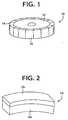
- Fig. 1 shows a disk-shaped grindstone 10 according to one embodiment of the present invention.
- This disk-shaped grindstone 10 is to be used for a super high speed grinding operation in which the grindstone 10 is rotated at a peripheral speed thereof equal to or larger than 100m/s.
- the disk-shaped grindstone 10 includes a base disk (metallic base) 12 which corresponds to a core portion of the grindstone 10, and abrasive segments 14 which correspond to an abrasive layer bonded to an outer circumferential surface of the base disk 12.
- the base disk 12 is made of an aluminum alloy, and has a circular shape and a large thickness.
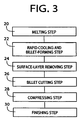
- Each of the abrasive segments 14 is a plate member which is curved so as to have a generally arcuate shape whose curvature is equal to that of the outer circumferential surface of the base disk 12, as shown in Fig. 2.
- the abrasive segments 14 are bonded to the outer circumferential surface of the base disk 12, for example, with an epoxy resin adhesive, such that the abrasive segments 14 are arranged in a circular array without any gap between adjacent ones of the abrasive segments 14.
- Each abrasive segment 14 consists of a radially outer layer 14 A which is dedicated exclusively to a grinding operation, and a radially inner layer 14 B which is formed integrally with the outer layer 14 in a simultaneous firing process.
- the radially inner layer 14 B functions as a base support layer for mechanically supporting the radially outer layer 14 A .
- Each of the radially outer and inner layers 14 A , 14 B consists of abrasive grains and an organic or inorganic bonding agent by which the abrasive grains are held together.
- the bonding agents used in the respective radially outer and inner layer 14 A , 14 B are the same in kind, while the abrasive grains used in the respective radially outer and inner layers 14 A , 14 B are different in kind from each other.
- the radially outer layer 14 A includes super abrasive grains, such as CBN abrasive grains or diamond abrasive grains, which have a Knoop hardness value of at least 3000, while the radially inner layer 14 B includes ordinary abrasive grains such as fused alumina abrasive grains or silicon carbide abrasive grains.
- the super abrasive grains are included in the radially outer layer 14 A such that the supper abrasive grains have a concentration of not larger than about 10-230, preferably, about 20-200.
- the supper abrasive grains have a size within a range of 60-800 meshes.
- the lower and upper limits of 60 meshes and 800 meshes respectively correspond to 220 ⁇ m and 20 ⁇ m in the average particle diameter.
- the supper abrasive grains are subjected to a heat treatment at a temperature of 400-1200°C under vacuum or in a gas atmosphere in the absence of oxygen, so as to reduce a toughness of the supper abrasive grains. If the temperature is lower than 400°C, the toughness of the supper abrasive gains is not sufficiently reduced. If the temperature is higher than 1200°C, the supper abrasive grains are excessively pulverized whereby the grinding performance and the durability of the supper abrasive grains are deteriorated.
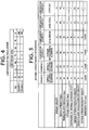
- the base disk 12 is produced, for example, according to a production process as shown in Fig. 3.
- a melting step 20 is first implemented to obtain a molten material which includes 15 wt%-40wt% of Si, 0.5wt%-6wt% of Cu, 0.2wt%-3wt% of Mg, and the remaining which is constituted principally by aluminum, by mixing and melting various kinds of materials put into a melting furnace (not shown). The amounts of the respective put materials are adjusted so as to obtain the above-described weight distribution. The above-described remaining includes impurities which inevitably enters the mixture in the production process.
- the melting step 20 is followed by a rapid-cooling and billet-forming step 22 in which, for example, a nitrogen gas is blasted to the flowing molten material obtained in the melting step 20, whereby the molten material is separated into small droplets, and then the small droplets are sprayed into a cylindrical forming space which is open in a surface of a collector.
- the sprayed droplets are rapidly cooled and start to be solidified, so that the droplets, which are melted or semi-melted, adhere to an inner wall surface of the cylindrical-shaped forming space of the collector.
- the melted or semi-melted droplets adhering to the inner wall surface of the forming space are cooled and solidified in the presence of the gas, while functioning as bonding agents for bonding themselves to each other, so that a cylindrical billet having a size of, for example, about 400mm ⁇ ⁇ 750mm is obtained.
- the rapid-cooling and billet-forming step 22 is followed by a surface-layer removing step 24 which is implemented to remove a surface layer of the cylindrical billet which layer has a high porosity and a thickness of, for example, about 5mm, by a machining operation.
- a billet cutting step 26 the cylindrical billet is cut to have a size of, for example, about 500mm which is slightly larger than that of the base disk 12.
- the billet cutting step 26 is followed by a compressing step 28 in which the cut billet is subjected to a densifying treatment so as to be compressed by cold- or hot-forging, hot-pressing, or extruding operation, so that the billet has a porosity not larger than 1 vol%.
- a finishing step 30 the billet is finished to have a desired size by a machining operation whereby the base disk 12 is finally obtained.
- the thus obtained base disk 12 has characteristics permitting a high speed grinding operation in which the disk-shaped grindstone 10 is rotated at a high peripheral speed not smaller than 100m/s. That is, the aluminum alloy constituting the base disk 12 has a light weight, and the Si particles deposited in the aluminum alloy by the rapid cooling are homogeneous and have a small size not larger than 5 ⁇ m. Further, the porosity of the aluminum alloy is reduced to be not larger than 1 vol%, so that the base disk 12 has a high degree of strength in its entirety and elastic elongation thereof is accordingly minimized.
- the tensile strength and the fatigue strength of the base disk 12 are thus increased, so that the ratio of the tensile strength to a specific gravity of the base disk 12 (tensile strength [MPa] / specific gravity) is not smaller than 90, and the ratio of the fatigue strength to the specific gravity of the base disk 12 (fatigue strength [MPa] / specific gravity) is not smaller than 30.
- the base disk 12 can be produced without any problem even if the base disk 12 has a large width so as to be used for a grindstone having a large width.
- a plurality of base disks 12 can be obtained at a single step of melting the aluminum alloy, thereby leading to a reduced manufacturing cost.
- the above-described reduced porosity of the aluminum alloy provides the base disk 12 with a high degree of corrosion resistance.
- the abrasive segments 14 can be easily removed from the base disk 12, by decomposing the adhesive with application of heat to the adhesive, or by dissolving the adhesive with a solvent.
- the high degree of corrosion resistance of the base disk 12 and the easy removal of the adhesive facilitate a reutilization of the base disk 12.
- the base disk 12 of the present embodiment is produced according to a production process similar to that as shown in Fig. 3.
- the base disk 12 is provided by an aluminum alloy including 15wt%-40wt% of Si, 0.5wt%-6wt% of Cu, 0.2 wt%-3wt% of Mg, 3wt%-10wt% of at least one of Fe, Mn and Ni, and the remaining which is constituted principally by aluminum.
- the aluminum alloy includes Si particles whose average diameter is not larger than 5 ⁇ m, and has a porosity not larger than 1 vol%.
- the ratio of a tensile strength of the base disk 12 to a specific gravity of the base disk 12 is not smaller than 90, and the ratio of a fatigue strength of the base disk 12 to the specific gravity of the base disk 12 (fatigue strength [MPa] / specific gravity) is not smaller than 30. That is, the base disk 12 of the present embodiment is different from the base disk 12 of the above-described embodiment, in that the base disk 12 of the present embodiment additionally includes 3wt%-10wt% of at least one of Fe, Mn and Ni, which is additionally put into the melting furnace at the above-described melting step 20.
- the present embodiment provides the same advantages as the above-described embodiment provides, and also the other advantage that the tensile strength and the fatigue strength of the base disk are further increased owing to the presence of 3wt%-10wt% of at least one of Fe, Mn and Ni therein.
- test piece which had the same composition as the base disk of the first embodiment and which was produced according to the same production process as that in the first embodiment
- Example 2 which had the same composition as the base disk of the second embodiment and which was produced according to the same production process as that in the second embodiment
- Comparative Example 1 which had the same composition as the base disk of the first embodiment and which was produced according to a powder metallurgical method
- Comparative Example 2 which was made of 4A aluminum alloy and which was produced according to a known method
- test piece (referred to as Comparative Example 3) which was made of a hard steel and which was produced according to a known method
- Comparative Example 4 which had
- the rapidly-solidified aluminum alloy of Example 1 had almost the same values of the specific gravity, elastic modulus and coefficient of thermal expansion as the powder metallurgical aluminum alloy of Comparative Example 1, but had a higher degree of tensile strength and a higher degree of fatigue strength than the aluminum alloy of Comparative Example 1. Accordingly, the aluminum alloy of Example 1 can be advantageously used as a base disk of a grindstone for use in a rotary grinding operation performed with a high peripheral speed. Further, as is apparent from the result of the immersion test, the rapidly-solidified aluminum alloys of Examples 1 and 2 had smaller amount of reduction in dimension than the powder metallurgical aluminum alloy of Comparative Example 1.
- the aluminum alloys of Examples 1 and 2 exhibited a higher degree of corrosion resistance than the aluminum alloy of Comparative Example 1. It is noted that a surface of the base disk may be coated, for example, with alumite by a suitable treatment, so that the base disk has an increased corrosion resistance.
- a base disk (outside diameter 237mm ⁇ ⁇ thickness 30mmT ⁇ mounting hole diameter 20mmH) was first produced according to the production process (as shown in Fig. 3) of the first embodiment, and abrasive segments (length 40mm ⁇ width 30mm ⁇ thickness 7mm) were then bonded to an outer circumferential surface of the base disk with an epoxy resin adhesive, so that a disk-shaped grindstone was formed.
- Each of the abrasive segments consisted of a radially outer layer (thickness 3mm) and a radially inner layer which were formed integrally with each other.
- the radially outer layer consisted of 50 parts by volume of CBN abrasives of #80 / #100, 16 parts by volume of vitrified bond and 34 parts by volume of pores.
- the radially inner layer consists of 50 parts by volume of mullite powders of #180/ #220, 16 parts by volume of vitrified bond and 34 parts by volume of pores.
- the formed disk-shaped grindstone was subjected to a destruction test with a spintester under vacuum, and the grindstone was destroyed when the value of peripheral speed of the grindstone was increased to 335m/s. If it is assumed that the peripheral speed in practical use can be increased to a half of the destruction value, it could be increased to 167m/s.
- the distortion amount in an outer peripheral portion of the grindstone upon the destruction was calculated as 5.9 ⁇ 10 -4 by FEM analysis.
- a disk-shaped grindstone (outside diameter 455mm ⁇ ⁇ thickness 100mmT ⁇ mounting hole diameter 203.2mmH) to be used for a centerless grinding operation was formed by using a base disk (outside diameter 439mm ⁇ ⁇ thickness 100mmT ⁇ mounting hole diameter 203.2mmH) which was produced according to the production process (as shown in Fig. 3) of the first embodiment.
- a centrifugal force or stress acting on the base disk during rotation of the grindstone at a peripheral speed of 100m/s was measured by FEM analysis, and the measured value was about 23MPa. In view of this measured value of the centrifugal force and also the values of the fatigue and tensile strengths of Example 1 which are shown in Fig.
- the factor of safety as to fatigue strength per a unit specific gravity should be at least three times while that as to tensile strength per the unit specific gravity should be at least about ten times, for assuring a sufficiently high degree of safety of the base disk.
Landscapes
- Engineering & Computer Science (AREA)
- Mechanical Engineering (AREA)
- Chemical & Material Sciences (AREA)
- Manufacturing & Machinery (AREA)
- Ceramic Engineering (AREA)
- Inorganic Chemistry (AREA)
- Polishing Bodies And Polishing Tools (AREA)
Applications Claiming Priority (3)
| Application Number | Priority Date | Filing Date | Title |
|---|---|---|---|
| JP35371498A JP3426522B2 (ja) | 1998-11-06 | 1998-11-06 | ベース円板型研削砥石 |
| JP35371498 | 1998-11-06 | ||
| PCT/JP1999/006186 WO2000027593A1 (fr) | 1998-11-06 | 1999-11-05 | Meule avec disque de base |
Publications (2)
| Publication Number | Publication Date |
|---|---|
| EP1046465A1 true EP1046465A1 (de) | 2000-10-25 |
| EP1046465A4 EP1046465A4 (de) | 2007-01-10 |
Family
ID=18432735
Family Applications (1)
| Application Number | Title | Priority Date | Filing Date |
|---|---|---|---|
| EP99954415A Withdrawn EP1046465A4 (de) | 1998-11-06 | 1999-11-05 | Schleifscheibe mit trägerplatte |
Country Status (5)
| Country | Link |
|---|---|
| US (1) | US6319109B1 (de) |
| EP (1) | EP1046465A4 (de) |
| JP (1) | JP3426522B2 (de) |
| KR (1) | KR100611936B1 (de) |
| WO (1) | WO2000027593A1 (de) |
Cited By (2)
| Publication number | Priority date | Publication date | Assignee | Title |
|---|---|---|---|---|
| WO2006054674A1 (ja) | 2004-11-19 | 2006-05-26 | Toyoda Van Moppes Ltd. | 砥石車 |
| CN109894991A (zh) * | 2019-03-28 | 2019-06-18 | 上海橄榄精密工具有限公司 | 组合物及其制得的砂轮 |
Families Citing this family (6)
| Publication number | Priority date | Publication date | Assignee | Title |
|---|---|---|---|---|
| US9266220B2 (en) | 2011-12-30 | 2016-02-23 | Saint-Gobain Abrasives, Inc. | Abrasive articles and method of forming same |
| JP2017532208A (ja) * | 2014-08-26 | 2017-11-02 | ナノ マテリアルズ インターナショナル コーポレイション | アルミニウム/ダイヤモンド切削工具 |
| DE102016105049B4 (de) * | 2016-03-18 | 2018-09-06 | Thyssenkrupp Ag | Verfahren zur Wiederbelegung eines Schleifwerkzeugs sowie wiederbelegbares Schleifwerkzeug hierzu |
| JP7034547B2 (ja) * | 2018-02-02 | 2022-03-14 | 株式会社ディスコ | 環状の砥石、及び環状の砥石の製造方法 |
| CN110125819A (zh) * | 2019-06-12 | 2019-08-16 | 郑州中岳机电设备有限公司 | 一种梯型钢板为底层的金属结合剂砂轮 |
| KR102379910B1 (ko) * | 2019-12-24 | 2022-03-29 | 이화다이아몬드공업 주식회사 | 피삭재의 표면가공을 위한 연삭휠 및 그 연삭휠의 트루잉 또는 드레싱 방법 |
Family Cites Families (16)
| Publication number | Priority date | Publication date | Assignee | Title |
|---|---|---|---|---|
| JPS5597447A (en) | 1979-01-19 | 1980-07-24 | Sumitomo Electric Ind Ltd | Aluminum sintered alloy and production of the same |
| JPS58191779A (ja) | 1982-05-01 | 1983-11-09 | Showa Denko Kk | 立方晶bn砥粒の改質法及び砥石の製造法 |
| US5552110A (en) * | 1991-07-26 | 1996-09-03 | Toyota Jidosha Kabushiki Kaisha | Heat resistant magnesium alloy |
| JPH05125473A (ja) * | 1991-11-01 | 1993-05-21 | Yoshida Kogyo Kk <Ykk> | アルミニウム基合金集成固化材並びにその製造方法 |
| JP2514542B2 (ja) | 1992-09-08 | 1996-07-10 | 大阪ダイヤモンド工業株式会社 | 超砥粒砥石 |
| JP2781131B2 (ja) | 1993-08-30 | 1998-07-30 | 住友軽金属工業株式会社 | 低線膨張急冷凝固アルミニウム合金およびその製造方法 |
| JP3189535B2 (ja) * | 1993-10-27 | 2001-07-16 | 豊田工機株式会社 | 砥石車 |
| JP2884031B2 (ja) | 1993-12-17 | 1999-04-19 | 旭ダイヤモンド工業株式会社 | メタルボンド超砥粒砥石及びその製造方法 |
| JPH0890424A (ja) | 1994-09-22 | 1996-04-09 | Mitsui Kensaku Toishi Kk | 研削砥石用の円盤状基台 |
| JPH08243926A (ja) * | 1995-03-08 | 1996-09-24 | Osaka Diamond Ind Co Ltd | 超砥粒砥石及びその製造方法 |
| JP2835425B2 (ja) | 1995-03-27 | 1998-12-14 | 大阪ダイヤモンド工業株式会社 | 砥石用台金並びに超砥粒砥石及びそれらの製造方法 |
| JPH09176771A (ja) * | 1995-10-27 | 1997-07-08 | Osaka Diamond Ind Co Ltd | 超砥粒砥石及びその製造方法 |
| JP3391636B2 (ja) * | 1996-07-23 | 2003-03-31 | 明久 井上 | 高耐摩耗性アルミニウム基複合合金 |
| JP3959766B2 (ja) * | 1996-12-27 | 2007-08-15 | 大同特殊鋼株式会社 | 耐熱性にすぐれたTi合金の処理方法 |
| JPH10202539A (ja) * | 1997-01-16 | 1998-08-04 | Jiibetsuku Technol:Kk | 加工材並びに回転工具 |
| US6074278A (en) * | 1998-01-30 | 2000-06-13 | Norton Company | High speed grinding wheel |
-
1998
- 1998-11-06 JP JP35371498A patent/JP3426522B2/ja not_active Expired - Fee Related
-
1999
- 1999-11-05 US US09/582,704 patent/US6319109B1/en not_active Expired - Fee Related
- 1999-11-05 WO PCT/JP1999/006186 patent/WO2000027593A1/ja not_active Ceased
- 1999-11-05 KR KR1020007007457A patent/KR100611936B1/ko not_active Expired - Fee Related
- 1999-11-05 EP EP99954415A patent/EP1046465A4/de not_active Withdrawn
Cited By (4)
| Publication number | Priority date | Publication date | Assignee | Title |
|---|---|---|---|---|
| WO2006054674A1 (ja) | 2004-11-19 | 2006-05-26 | Toyoda Van Moppes Ltd. | 砥石車 |
| EP1813387A4 (de) * | 2004-11-19 | 2009-12-23 | Toyoda Van Moppes Ltd | Schleifscheibe |
| US7695353B2 (en) | 2004-11-19 | 2010-04-13 | Toyoda Van Moppes Ltd. | Grinding wheel |
| CN109894991A (zh) * | 2019-03-28 | 2019-06-18 | 上海橄榄精密工具有限公司 | 组合物及其制得的砂轮 |
Also Published As
| Publication number | Publication date |
|---|---|
| JP2000141231A (ja) | 2000-05-23 |
| KR100611936B1 (ko) | 2006-08-11 |
| WO2000027593A1 (fr) | 2000-05-18 |
| JP3426522B2 (ja) | 2003-07-14 |
| EP1046465A4 (de) | 2007-01-10 |
| US6319109B1 (en) | 2001-11-20 |
| KR20010033885A (ko) | 2001-04-25 |
Similar Documents
| Publication | Publication Date | Title |
|---|---|---|
| AU732575B2 (en) | Abrasive tools | |
| US6093092A (en) | Abrasive tools | |
| EP1144160B1 (de) | Superabschleifendes schleifwerkzeug mit einer aktivbindung | |
| JP2003512937A (ja) | 剛直に結合された薄い砥石 | |
| US6319109B1 (en) | Disk-shaped grindstone | |
| JP3538360B2 (ja) | 重研削用のレジノイド研削砥石 | |
| JP2001139936A (ja) | 単結晶ダイヤモンド又はダイヤモンド焼結体研磨用砥石及び同研磨方法並びに研磨により得られた単結晶ダイヤモンド及びダイヤモンド焼結体 | |
| JP3359482B2 (ja) | 超砥粒ホイール及びその製造方法 | |
| JPH08150567A (ja) | ビトリファイドボンドダイヤモンド砥石およびその製造方法 | |
| JPH10138150A (ja) | ベース円板型研削砥石 | |
| JPH10202533A (ja) | ダイヤモンド切断砥石 | |
| JP2002187071A (ja) | 電鋳薄刃砥石 | |
| JP2001170869A (ja) | 研削砥石用台金および刃物 | |
| MXPA00009489A (en) | Abrasive tools | |
| JPH03104565A (ja) | 有気孔メタル砥石の遠心焼成法 | |
| HK1034221B (en) | Abrasive tools | |
| JPH10202532A (ja) | レジノイド研削砥石 | |
| JPS61244465A (ja) | 硬質物含有材料用研削砥石及びその使用方法 | |
| JPH09176771A (ja) | 超砥粒砥石及びその製造方法 | |
| JP2003251566A (ja) | サーメットを基板とする超砥粒切断ホイ−ル | |
| JPH0398767A (ja) | メタルボンド工具の製造方法 |
Legal Events
| Date | Code | Title | Description |
|---|---|---|---|
| PUAI | Public reference made under article 153(3) epc to a published international application that has entered the european phase |
Free format text: ORIGINAL CODE: 0009012 |
|
| AK | Designated contracting states |
Kind code of ref document: A1 Designated state(s): DE FR |
|
| 17P | Request for examination filed |
Effective date: 20001114 |
|
| A4 | Supplementary search report drawn up and despatched |
Effective date: 20061123 |
|
| 17Q | First examination report despatched |
Effective date: 20071018 |
|
| STAA | Information on the status of an ep patent application or granted ep patent |
Free format text: STATUS: THE APPLICATION IS DEEMED TO BE WITHDRAWN |
|
| 18D | Application deemed to be withdrawn |
Effective date: 20080229 |