EP1046471A1 - Cassette de rasage flexible - Google Patents
Cassette de rasage flexible Download PDFInfo
- Publication number
- EP1046471A1 EP1046471A1 EP20000302936 EP00302936A EP1046471A1 EP 1046471 A1 EP1046471 A1 EP 1046471A1 EP 20000302936 EP20000302936 EP 20000302936 EP 00302936 A EP00302936 A EP 00302936A EP 1046471 A1 EP1046471 A1 EP 1046471A1
- Authority
- EP
- European Patent Office
- Prior art keywords
- blade
- frame
- ribs
- razor
- flexible beam
- Prior art date
- Legal status (The legal status is an assumption and is not a legal conclusion. Google has not performed a legal analysis and makes no representation as to the accuracy of the status listed.)
- Granted
Links
- 230000007935 neutral effect Effects 0.000 claims abstract description 4
- 238000005520 cutting process Methods 0.000 claims description 19
- 239000008257 shaving cream Substances 0.000 description 8
- 239000004480 active ingredient Substances 0.000 description 4
- 239000003795 chemical substances by application Substances 0.000 description 4
- 230000000712 assembly Effects 0.000 description 3
- 238000000429 assembly Methods 0.000 description 3
- 241000196324 Embryophyta Species 0.000 description 2
- 229920003171 Poly (ethylene oxide) Polymers 0.000 description 2
- GWEVSGVZZGPLCZ-UHFFFAOYSA-N Titan oxide Chemical compound O=[Ti]=O GWEVSGVZZGPLCZ-UHFFFAOYSA-N 0.000 description 2
- 150000001875 compounds Chemical class 0.000 description 2
- 238000010276 construction Methods 0.000 description 2
- -1 e.g. Substances 0.000 description 2
- 238000004519 manufacturing process Methods 0.000 description 2
- 239000000463 material Substances 0.000 description 2
- 230000000717 retained effect Effects 0.000 description 2
- 239000007787 solid Substances 0.000 description 2
- 235000002961 Aloe barbadensis Nutrition 0.000 description 1
- 244000186892 Aloe vera Species 0.000 description 1
- 241000894006 Bacteria Species 0.000 description 1
- 241000252203 Clupea harengus Species 0.000 description 1
- 229920002907 Guar gum Polymers 0.000 description 1
- 239000004743 Polypropylene Substances 0.000 description 1
- 239000004793 Polystyrene Substances 0.000 description 1
- XUIMIQQOPSSXEZ-UHFFFAOYSA-N Silicon Chemical compound [Si] XUIMIQQOPSSXEZ-UHFFFAOYSA-N 0.000 description 1
- DBMJMQXJHONAFJ-UHFFFAOYSA-M Sodium laurylsulphate Chemical compound [Na+].CCCCCCCCCCCCOS([O-])(=O)=O DBMJMQXJHONAFJ-UHFFFAOYSA-M 0.000 description 1
- 239000004141 Sodium laurylsulphate Substances 0.000 description 1
- 238000005299 abrasion Methods 0.000 description 1
- 235000011399 aloe vera Nutrition 0.000 description 1
- 238000013459 approach Methods 0.000 description 1
- 230000009286 beneficial effect Effects 0.000 description 1
- 230000002457 bidirectional effect Effects 0.000 description 1
- 230000000740 bleeding effect Effects 0.000 description 1
- 229920001400 block copolymer Polymers 0.000 description 1
- 210000004204 blood vessel Anatomy 0.000 description 1
- 210000001124 body fluid Anatomy 0.000 description 1
- 210000000988 bone and bone Anatomy 0.000 description 1
- 239000012459 cleaning agent Substances 0.000 description 1
- 239000000701 coagulant Substances 0.000 description 1
- 230000003750 conditioning effect Effects 0.000 description 1
- 239000002537 cosmetic Substances 0.000 description 1
- 238000005336 cracking Methods 0.000 description 1
- 230000002951 depilatory effect Effects 0.000 description 1
- 239000003599 detergent Substances 0.000 description 1
- 230000000694 effects Effects 0.000 description 1
- 230000008030 elimination Effects 0.000 description 1
- 238000003379 elimination reaction Methods 0.000 description 1
- 239000000796 flavoring agent Substances 0.000 description 1
- 235000013355 food flavoring agent Nutrition 0.000 description 1
- 239000003205 fragrance Substances 0.000 description 1
- 150000004676 glycans Chemical class 0.000 description 1
- 238000009499 grossing Methods 0.000 description 1
- 239000000665 guar gum Substances 0.000 description 1
- 229960002154 guar gum Drugs 0.000 description 1
- 235000010417 guar gum Nutrition 0.000 description 1
- 235000019514 herring Nutrition 0.000 description 1
- 239000004615 ingredient Substances 0.000 description 1
- 239000000314 lubricant Substances 0.000 description 1
- 210000002751 lymph Anatomy 0.000 description 1
- 239000011159 matrix material Substances 0.000 description 1
- 239000002480 mineral oil Substances 0.000 description 1
- 239000000203 mixture Substances 0.000 description 1
- 239000003921 oil Substances 0.000 description 1
- 239000000049 pigment Substances 0.000 description 1
- 229920002401 polyacrylamide Polymers 0.000 description 1
- 229920001155 polypropylene Polymers 0.000 description 1
- 229920001282 polysaccharide Polymers 0.000 description 1
- 239000005017 polysaccharide Substances 0.000 description 1
- 229920002223 polystyrene Polymers 0.000 description 1
- 229910052710 silicon Inorganic materials 0.000 description 1
- 239000010703 silicon Substances 0.000 description 1
- 229920002545 silicone oil Polymers 0.000 description 1
- 230000037380 skin damage Effects 0.000 description 1
- 235000019333 sodium laurylsulphate Nutrition 0.000 description 1
- 239000000126 substance Substances 0.000 description 1
- 230000001629 suppression Effects 0.000 description 1
- 239000004408 titanium dioxide Substances 0.000 description 1
- 239000000341 volatile oil Substances 0.000 description 1
- XLYOFNOQVPJJNP-UHFFFAOYSA-N water Substances O XLYOFNOQVPJJNP-UHFFFAOYSA-N 0.000 description 1
- 229920003176 water-insoluble polymer Polymers 0.000 description 1
Images




Classifications
-
- B—PERFORMING OPERATIONS; TRANSPORTING
- B26—HAND CUTTING TOOLS; CUTTING; SEVERING
- B26B—HAND-HELD CUTTING TOOLS NOT OTHERWISE PROVIDED FOR
- B26B21/00—Razors of the open or knife type; Safety razors or other shaving implements of the planing type; Hair-trimming devices involving a razor-blade; Equipment therefor
- B26B21/08—Razors of the open or knife type; Safety razors or other shaving implements of the planing type; Hair-trimming devices involving a razor-blade; Equipment therefor involving changeable blades
- B26B21/14—Safety razors with one or more blades arranged transversely to the handle
- B26B21/22—Safety razors with one or more blades arranged transversely to the handle involving several blades to be used simultaneously
- B26B21/222—Safety razors with one or more blades arranged transversely to the handle involving several blades to be used simultaneously with the blades moulded into, or attached to, a changeable unit
- B26B21/225—Safety razors with one or more blades arranged transversely to the handle involving several blades to be used simultaneously with the blades moulded into, or attached to, a changeable unit the changeable unit being resiliently mounted on the handle
-
- B—PERFORMING OPERATIONS; TRANSPORTING
- B26—HAND CUTTING TOOLS; CUTTING; SEVERING
- B26B—HAND-HELD CUTTING TOOLS NOT OTHERWISE PROVIDED FOR
- B26B21/00—Razors of the open or knife type; Safety razors or other shaving implements of the planing type; Hair-trimming devices involving a razor-blade; Equipment therefor
- B26B21/40—Details or accessories
- B26B21/4068—Mounting devices; Manufacture of razors or cartridges
-
- B—PERFORMING OPERATIONS; TRANSPORTING
- B26—HAND CUTTING TOOLS; CUTTING; SEVERING
- B26B—HAND-HELD CUTTING TOOLS NOT OTHERWISE PROVIDED FOR
- B26B21/00—Razors of the open or knife type; Safety razors or other shaving implements of the planing type; Hair-trimming devices involving a razor-blade; Equipment therefor
- B26B21/40—Details or accessories
- B26B21/52—Handles, e.g. tiltable, flexible
- B26B21/521—Connection details, e.g. connection to razor heads
Definitions
- the present invention relates to flexible razor cartridges and razor assemblies having such flexible cartridges.
- the present invention overcomes the drawbacks of the prior art by providing a razor cartridge which may include one or more blades which utilizes flexible beams to provide enhanced flexibility.
- One aspect of the present invention is directed toward a flexible razor cartridge comprising a frame and at least one blade having top and bottom surfaces supported on the frame.
- the at least one blade extends longitudinally along the frame and is movable along with the frame upon application of a force encountered during shaving between an at rest position where the at least one blade is in a substantially planar configuration and a flexed position where the at least one blade is in a substantially concave or convex configuration with respect to the top surface thereof.
- the razor cartridge also comprises at least one flexible beam secured to the frame below the bottom surface of the at least one blade and extending longitudinally therewith.
- the flexible beam is normally arranged in a neutral position when the at least one blade is in its at rest position.
- the at least one flexible beam is deformable to a flexed position along with the at least one blade, where it is biased to facilitate the at least one blade and the frame of the razor cartridge to return to their at rest position.
- the blades of the razor cartridge may include a front end where a cutting edge is formed and a rear end remote from the cutting edge.
- the at least one flexible beam may comprise a plurality of hills and valleys where the hills are arranged closer to the rear end of the at least one blade and the valleys are arranged closer to the front end of the at least one blade.
- the frame of the razor cartridge may comprise a plurality of ribs which extend at least partially below the bottom surface of the bottom blade.
- the ribs may extend transversely to the longitudinally extending flexible beam and associated blades.
- the flexible beam may comprise a plurality of segments arranged between consecutive ones of the ribs.
- the razor cartridge of this aspect of the present invention may also comprise a guard bar and a cap.
- one of the flexible beams may be arranged below the guard bar while another of the flexible beams may be arranged below the cap.
- such segments may be substantially u-shaped.
- Another aspect of the present invention is directed to a razor cartridge as claimed in Claim 14.
- the razor cartridge includes flexible beam means attached to the frame thereof which extend longitudinally therealong for facilitating associated blades and the frame to return from the flexed position to the at rest position.
- the flexible beam means may be arranged below the bottom surface of the bottom blade.
- razor assemblies are provided, as claimed in Claims 23 and 36.
- Each of the razor assemblies comprises one of the flexible razor cartridges as referred to above in combination with a handle.
- the razor assembly 10 includes a cartridge 11 and an associated handle assembly 94.
- the cartridge 11 has opposing first and second end members 12 and 14 with a central section of a frame generally designated 16 extending therebetween.
- the frame 16 is integral with the first and second opposing end members 12 and 14.
- the cartridge 11 shown in the preferred embodiment of FIG. 1 is a triple bladed cartridge including a seat blade 24, an intermediate blade 36 and a top blade 48, various aspects of the present invention may be used with a cartridge having more or less than three blades.
- the cartridge 11 includes a seat blade 24 having a cutting edge 26 and a rear edge 28.
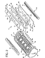
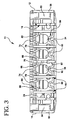
- the seat blade 24 includes a top surface 30 and a bottom surface 32. As best shown in FIGS. 2 and 3, the seat blade 24 includes a plurality of large wash-through holes 34. In a preferred embodiment, each of the wash-through holes 34 is larger than the wash-through holes of prior art razor blades, and may encompass a total area of about 8.0-13.0 mm 2 , and is more preferably about 12.3 mm 2 . Of course, in alternate embodiments, the size of the wash-through holes 34 may vary outside of the preferred range. As shown in FIG. 2, the seat blade 24 is supported on the frame 16 in an aligned row of slots 20 of corresponding ribs 18.
- the intermediate blade 36 also includes a cutting edge 38, a rear edge 40, a top surface 42 and a bottom surface 44.
- a plurality of wash-through holes 46 are arranged between the cutting and rear edges 38 and 40 so as to create a passageway between the top and bottom surfaces 42-44.
- the wash-through holes 46 are also substantially larger than the wash-through holes of prior art razor blades and each may encompass a total area of about 5.0-7.0 mm 2 , and is more preferably about 6.4 mm 2 .
- the size of the wash-through holes 34 may vary outside of the preferred range.
- wash-through holes 34 of the seat blade 24 are larger than the wash-through holes 46 of the intermediate blade 36.
- the particular geometric configuration and dimensions of wash-through holes 34 and 46 may vary substantially in alternate embodiments of the present invention.
- each of the wash-through holes may encompass a total area of at least 4 mm 2 .
- each of the wash-through holes in the various blades of cartridge 11 may encompass a total area of less than 4 mm 2 .
- the cartridge 11 also includes a top blade 48. Unlike the seat blade 24 and the intermediate blade 36, the top blade 48 need not include any wash-through holes. In a preferred embodiment, the top blade 48 is somewhat conventional in that it includes a cutting edge 50, a rear edge 52, a top surface 54 and a bottom surface 56. However, in alternate embodiments, the top blade 48 may also include wash-through holes.
- the associated razor blades i.e., seat blade 24, intermediate blade 36 and top blade 48
- the present invention is not limited to any particular blade dimension, configuration or geometry.
- the entire razor assembly 10 of the present invention is disposable. However, in alternate embodiments of the present invention, only the cartridge may be disposable.
- wash-through holes 34 and 46 are to facilitate removal of shaving cream and hair which may become lodged between blade surfaces during shaving.
- the cartridge 11 is generally designed to maximize rinsability (i.e., wash-through). While one aspect of the improved wash-through is due to the arrangement of the wash-through holes, another aspect relates to the straight wash-through as discussed below.
- wash-through holes 34 and 46 It is desirable to maximize the overlap of the wash-through holes 34 and 46.
- the wash-through holes 34 of the seat blade 24 are larger than the wash-through holes 46 of the intermediate blade 36, it is desirable to maximize the area of each wash-through hole 34 arranged directly above a corresponding area of one of the wash-through holes 46.
- a relatively small distance may exist between the forward-most portion of wash-through holes 46 and the forward-most edge of intermediate blade 36.
- the edge of intermediate blade 36 may be positioned so that it is actually arranged over a portion of the wash-through holes 46. While this arrangement is desirable from a wash-through perspective, it is difficult to achieve due to desired span and exposure, dimensions and angles.
- each wash-through hole 34 it is also desirable for the side edges of each wash-through hole 34 to be arranged over a corresponding wash-through hole 46. However, in alternate embodiments, it is not necessary for the side edges of wash-through holes 34 to overlap corresponding wash-through holes 46.
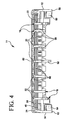
- the cartridge 11 facilitates a straight wash-through (i.e., from the front through the rear of the blades) of otherwise trapped shaving cream and hair in that it does not include a solid rear wall. Instead, the only rear wall sections of the cartridge 11 are those associated with first and second end members 12 and 14 and the rear faces 22 of the ribs 18. As illustrated in FIG. 4, the cartridge 11 includes relatively large open sections 66 through which deposited shaving cream and hair can be rinsed. This aspect of the present invention will also be discussed further below in connection with the operation thereof.
- the open sections 66 encompass a greater width than the solid wall sections, such as the width of rear faces 22 of rib 18.
- each of the open sections 66 may have a width of about 5.2 mm, while the width defined by each of the rear faces 22 of ribs 18 may be about 0.8 mm.
- the first end member 12 includes an arcuate bottom surface 58 and a journalled end member 60 which extends inwardly toward the second side member 14.
- the second side member 14 includes an arcuate bottom surface 62 and a journalled end member 64 which extends inwardly toward the first end member 12.
- the journalled end construction of cartridge 11 is an innovative feature which facilitates improved pivotability between the cartridge 11 and handle assembly 94.
- the journalled end members 60 and 64 are tapered inwardly to allow the cartridge to pivot while it is in a flexed configuration.
- the axis about which the cartridge 11 pivots extends between the cap 80 and guard bar 72, and is located on the shave plane (i.e., a tangent line between the cap and the guard bar). This arrangement optimizes blade contact with a person's skin during shaving.
- journalled end members 60 and 64 are integral with their corresponding side members 12 and 14 and extend inwardly toward the other side member. Further, journalled end members 60 and 64 preferably follow the contour of associated arcuate bottom surfaces 58 and 62, respectively.
- the razor blades 24, 36 and 48 may be secured in assembled position within the cartridge frame 16 by posts (not shown) which extend through corresponding post holes 70 (FIG. 2) arranged near the rear section of all of the blades.
- posts may be formed when the cartridge 11 including the blades are retained in a fixture.
- Outer holes 71 may have the same configuration as post holes 70, but are used to locate the razor blades 24, 36 and 48 during the manufacturing process.
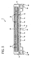
- the cartridge 11 is shown in FIGS. 1, 2 and 5 as including a guard bar 72.
- a guard bar is designed to be the first element of a safety razor to contact a person's skin during the shaving stroke.
- the guard bar 72 will control the manner in which the skin approaches the cutting edge 26 of the seat blade 24.
- the guard bar 72 may be a molded rubber strip 70 having a herring bone design or other desired design to facilitate the flow of skin over the guard bar segments during shaving.
- each of the segments 74 are formed on a portion of a front horizontal beam 84 (described further below), while each of the segments 76 are formed on the forward-most portion of corresponding ribs 18.
- the cartridge 11 also includes a cap 80, which forms a part of frame 16.
- the cap 80 is arranged above and in back of the top blade 48.
- a shaving aid 82 may be arranged on cap 80.
- Various materials have been used in the prior art as shaving aids and may also be used in connection with the present invention.
- the term "shaving aid" as used herein, refers equally either to the active ingredient combined with a delivery system, such as a water-insoluble microporous matrix structure or to the active ingredient alone.
- Previously suggested active ingredients include those in U.S. Patent No. 4,170,821 to Booth, which is hereby incorporated by reference.
- a shaving aid may comprise one of various combinations of the following:
- the shaving aid may comprise one or more of these shaving aids disclosed in U.S. Patent Nos. 5,056,221; 4,044,120; and 5,095,619, which are also incorporated herein by references.
- activate ingredients may include various pigments, e.g., titanium dioxide, fragrances, aloe vera, flavoring agents, mineral oils, essential oils and other oils derived from plants.
- the shaving aids of the present invention may also comprise other compounds or blends of compounds such as water insoluble polymers such as polystyrene and polypropylene.
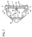
- the razor cartridge 11 is constructed and arranged to flex through an imaginary plane which extends through the shaving aid 82. Such flexing of the razor cartridge 11 is shown in FIGS. 7 and 8. When the razor cartridge 11 flexes, each of the razor blades 24, 36 and 48 bend from their rest position, where they have a substantially planar configuration to a configuration where the top surfaces thereof obtain a concave configuration. However, it should also be appreciated that the razor cartridge 11 may also flex so that the blades obtain a convex configuration with respect to the top surfaces thereof. Such flexing may be desirable in, for example, a women's razor.
- the intermediate and seat blades 36 and 24 slide longitudinally relative to each other within slots 20. This arrangement further facilitates flexibility of the cartridge and allows the vertical spacing between the blades to remain substantially constant during flexing
- the cartridge 11 includes horizontally extending beams, such as front beam 84 and rear beam 88 which facilitate the flexible nature of the cartridge 11.
- the front horizontal beam 84 comprises a plurality of segments 86 which collectively form a saw-tooth pattern.
- the cartridge 11 also includes a rear horizontally extending beam 88 that comprises separate segments 90 which have an appearance substantially similar to the collective appearance of the segments of the front horizontal beam 84.
- the segments 86 and 90 are arranged between respective ribs 18 on the cartridge frame 16.
- the segments 86 of front beam 84 are formed in conjunction with guard bar segments 74, as best illustrated in FIG. 3.
- the structure of the front beam 84 and rear beam 88 are also inventive in various ways including their generally horizontally extending structure.
- the connection between the segments 86 of the front horizontally extending beam 84 and guard bar segments 74 is inventive.
- the front beam 84 and rear beam 88 are generally constructed and arranged to flex along with cartridge frame 16 when an appropriate force is encountered during shaving. Upon flexing, horizontal beams 84 and 88 are placed under tension and thus bias the cartridge frame 16 to return to its at-rest position where the blades 24, 36 and 48 are in a substantially planar configuration. Thus, one function of horizontal beams 84 and 88 is to bias the razor cartridge 11 to return to its at-rest position from a flexed position.
- the razor assembly 10 includes a cartridge 11 which is both flexible and pivotable.
- the center rib 18 includes a downwardly extending bearing surface 92 which, is used, in a preferred embodiment to facilitate pivoting of the cartridge 11 as discussed below.
- the center rib 18 also includes a notch 97 to provide clearance from a contact surface 106 of a spring arm 104 to allow the cartridge 11 to flex where the top surface of the blades obtain a concave configuration.
- the notch 97 includes an upper surface that acts as a stop with respect to the contact surface 106 so that the cartridge 11 will not overflex.
- the razor assembly 10 also includes a handle assembly 94 on which the cartridge 11 is pivotably mounted.
- the handle assembly 94 includes first and second side curved journal members 96 and 100, respectively.
- This aspect of the present invention is shown in FIGS. 1 and 6-10.
- the first side curved journal member 96 includes capture member 98 while the second side curved journal member 100 includes capture member 102.
- the cartridge 11 is mounted on the handle assembly 94 by securing the arcuate journalled end members 60 and 64 on corresponding first and second curved journal members 96 and 100. More particularly, the curved journalled end members 60 and 64 of cartridge 11 are arranged within the curved passageway formed between a corresponding one of the curved journal members 96 and 100 and their respective capture members 98 and 102.
- This mounting structure may be considered a "clam shell" pivot arrangement formed by the cooperating curved journal members 96 and 100 with the curved journalled end members 60 and 64 of the cartridge 11.
- the cartridge 11 of razor assembly 10 is initially biased to its rear-most position.
- this rearward biased cartridge arrangement is also referred to as a "unidirectional" pivot arrangement.
- Such arrangement has certain advantages such as the elimination of deadband (i.e., where the cartridge is not under a spring-loaded or other bias force). The existence of deadband is undesirable because it may result in vibration of the cartridge 11 during handling of the razor assembly 10.
- deadband i.e., where the cartridge is not under a spring-loaded or other bias force
- the existence of deadband is undesirable because it may result in vibration of the cartridge 11 during handling of the razor assembly 10.
- the particular pivot arrangement may be modified in alternate embodiments of the present invention.
- a forward biased (also unidirectional) or center biased pivot arrangement (bidirectional) may be used in place of the rearward biased pivot arrangement.
- an upwardly extending spring arm 104 extends from an end of the handle assembly 94.
- the spring arm 104 includes contact surface 106 at a top portion thereof which engages the downwardly extending bearing surface 92 from the center rib 18 of the cartridge 11. This structure urges the cartridge 11 to pivot to its rear-most position when the razor assembly 10 is not in use.
- the contact surface 106 of spring arm 104 includes two bosses that provide a groove through a central portion of contact surface 106.
- the groove (unnumbered) receives the center rib 18 of the cartridge 11.
- the journalled end members 60 and 64 open up as illustrated in FIG. 7.
- the groove between the bosses maintain the cartridge 11 in a centered position.
- the spring arm 104 has a substantially elongated triangular shape which provides for a desired degree of stiffness to help prevent side-to-side travel of cartridge 11. As best shown in FIGS. 6 and 7, a central portion of the triangular shaped spring arm 104 is cut away to provide the desired spring effect and to allow the center rib 18 of the cartridge 11 to rotate during flexing and/or pivoting of the cartridge 11.
- an integral "pivot frame" 103 is provided.
- the pivot frame 103 includes the spring arm 104 and the first and second curved journal members 96 and 100.
- the integral nature of the pivot frame 103 provides for manufacturing and structural advantages.
- FIGS. 1 and 9 illustrate the razor assembly 10 when arranged in its at rest position prior to shaving.
- the cartridge 11 may pivot forwardly (as shown in FIG. 10) on the clam-shell connector structure formed by the first and second bearing surfaces 96 and 100, and curved capture members 98 and 102 of the handle assembly 94 in combination with the curved journalled end members 60 and 64 of the cartridge 11.
- the cartridge 11 is constructed and arranged to flex through an imaginary plane which extends through the shaving aid 82. Such arrangement is designed to extend the life of the shaving aid 82 by minimizing cracking and wear thereof.
Landscapes
- Life Sciences & Earth Sciences (AREA)
- Forests & Forestry (AREA)
- Engineering & Computer Science (AREA)
- Mechanical Engineering (AREA)
- Packaging Of Annular Or Rod-Shaped Articles, Wearing Apparel, Cassettes, Or The Like (AREA)
- Dry Shavers And Clippers (AREA)
Applications Claiming Priority (2)
| Application Number | Priority Date | Filing Date | Title |
|---|---|---|---|
| US09/295,880 US6182366B1 (en) | 1999-04-21 | 1999-04-21 | Flexible razor assembly and cartridge |
| US295880 | 1999-04-21 |
Publications (2)
| Publication Number | Publication Date |
|---|---|
| EP1046471A1 true EP1046471A1 (fr) | 2000-10-25 |
| EP1046471B1 EP1046471B1 (fr) | 2005-06-29 |
Family
ID=23139606
Family Applications (1)
| Application Number | Title | Priority Date | Filing Date |
|---|---|---|---|
| EP00302936A Expired - Lifetime EP1046471B1 (fr) | 1999-04-21 | 2000-04-07 | Cassette de rasage flexible |
Country Status (6)
| Country | Link |
|---|---|
| US (1) | US6182366B1 (fr) |
| EP (1) | EP1046471B1 (fr) |
| JP (1) | JP2000312782A (fr) |
| AU (1) | AU780867B2 (fr) |
| CA (1) | CA2301466A1 (fr) |
| DE (1) | DE60021014T2 (fr) |
Cited By (6)
| Publication number | Priority date | Publication date | Assignee | Title |
|---|---|---|---|---|
| WO2005007355A1 (fr) * | 2003-07-07 | 2005-01-27 | Eveready Battery Company, Inc. | Cartouche de rasage pivotante et rasoir comprenant ladite cartouche |
| AU780144B2 (en) * | 1999-04-21 | 2005-03-03 | Edgewell Personal Care Brands, Llc | Pivotable and flexible razor assembly and cartridge |
| WO2006081840A1 (fr) * | 2005-02-03 | 2006-08-10 | Bic-Violex Sa | Manche de rasoir comportant une partie de tete reticulee |
| US7874076B2 (en) | 2005-02-03 | 2011-01-25 | Bic Violex Sa | Razor handle having ergonomic ribbed sides |
| US7934320B2 (en) | 2005-02-03 | 2011-05-03 | Bic-Violex Sa | Razor handle having an arcuate profile |
| US7975389B2 (en) | 2005-02-03 | 2011-07-12 | Bic-Violex Sa | Razor handle having ergonomic gripping areas |
Families Citing this family (42)
| Publication number | Priority date | Publication date | Assignee | Title |
|---|---|---|---|---|
| CA2276882C (fr) * | 1999-07-02 | 2000-05-02 | Stephen Macneil | Dispositif pour tailler une barbe ou une moustache |
| US6675479B1 (en) * | 2000-02-29 | 2004-01-13 | The Gillette Company | Shaving razor and blade unit with improved guard |
| USD472017S1 (en) * | 2001-06-07 | 2003-03-18 | American Safety Razor Company | Razor cartridge having a dual purpose soap bar |
| US6854188B1 (en) * | 2002-10-24 | 2005-02-15 | American Safety Razor Company | One-piece spring for razor handle |
| SE0300989D0 (sv) * | 2003-04-04 | 2003-04-04 | Electrolux Ab | Device for a pole saw |
| USD509322S1 (en) | 2004-06-09 | 2005-09-06 | American Safety Razor Company | Razor with protective cap |
| USD527491S1 (en) | 2004-06-09 | 2006-08-29 | American Safety Razor Company | Razor lube bar |
| USD509025S1 (en) | 2004-06-09 | 2005-08-30 | American Safety Razor Company | Razor |
| US8307552B1 (en) | 2005-04-28 | 2012-11-13 | Drouillard Gerald E | Heatable shaving accessory |
| US7748121B2 (en) | 2005-05-06 | 2010-07-06 | Eveready Battery Company, Inc. | Razor blade and support assembly |
| JP2006315965A (ja) * | 2005-05-10 | 2006-11-24 | Shiseido Co Ltd | 油性シェービング用組成物 |
| USD569038S1 (en) | 2007-07-24 | 2008-05-13 | Eveready Battery Company, Inc. | Safety razor |
| USD569551S1 (en) | 2007-07-24 | 2008-05-20 | Eveready Battery Company, Inc. | Safety razor |
| USD588309S1 (en) | 2008-02-15 | 2009-03-10 | American Safety Razor | Razor cartridge |
| USD625883S1 (en) | 2009-11-30 | 2010-10-19 | American Safety Razor | Razor cartridge |
| USD633253S1 (en) | 2010-06-23 | 2011-02-22 | American Safety Razor | Razor cartridge |
| USD640415S1 (en) | 2010-07-07 | 2011-06-21 | American Safety Razor | Razor cartridge |
| USD648075S1 (en) | 2010-07-07 | 2011-11-01 | American Safety Razor | Razor cartridge |
| US8745882B2 (en) | 2010-09-29 | 2014-06-10 | The Gillette Company | Flexible and separable portion of a razor handle |
| US8745883B2 (en) | 2010-09-29 | 2014-06-10 | The Gillette Company | Razor handle with a rotatable portion |
| USD643976S1 (en) | 2010-10-19 | 2011-08-23 | American Safety Razor | Razor cartridge |
| USD643977S1 (en) | 2010-10-19 | 2011-08-23 | American Safety Razor | Razor cartridge |
| US8938885B2 (en) | 2012-05-01 | 2015-01-27 | The Gillette Company | Razor handle with a rotatable portion |
| US9283685B2 (en) | 2012-07-26 | 2016-03-15 | Shavelogic, Inc. | Pivoting razors |
| US9486930B2 (en) | 2012-09-27 | 2016-11-08 | Shavelogic, Inc. | Shaving systems |
| WO2014051842A1 (fr) | 2012-09-27 | 2014-04-03 | Shavelogic, Inc. | Systèmes de rasage |
| WO2014051843A1 (fr) | 2012-09-28 | 2014-04-03 | Shavelogic, Inc. | Systèmes de rasage |
| US9623575B2 (en) | 2012-12-18 | 2017-04-18 | Shavelogic, Inc. | Shaving systems |
| US20150158192A1 (en) | 2013-12-09 | 2015-06-11 | Shavelogic, Inc. | Multi-material pivot return for shaving systems |
| CN203738831U (zh) * | 2013-12-31 | 2014-07-30 | 黄志坚 | 手动剃须刀 |
| WO2015142663A1 (fr) | 2014-03-21 | 2015-09-24 | Shavelogic, Inc. | Rappel par ressort métallique |
| US9527220B1 (en) | 2016-02-10 | 2016-12-27 | Gerald E. Drouillard | Heat-applying shaving device |
| EP3429809B1 (fr) | 2016-03-18 | 2021-07-28 | Personal Care Marketing And Research, Inc. | Cartouche de rasoir |
| US9993931B1 (en) | 2016-11-23 | 2018-06-12 | Personal Care Marketing And Research, Inc. | Razor docking and pivot |
| USD886377S1 (en) * | 2018-07-12 | 2020-06-02 | Shavelogic, Inc. | Razor cartridge |
| USD870380S1 (en) * | 2018-07-12 | 2019-12-17 | Shavelogic, Inc. | Razor cartridge |
| USD870969S1 (en) * | 2018-07-12 | 2019-12-24 | Shavelogic, Inc. | Razor cartridge |
| USD884971S1 (en) | 2019-02-27 | 2020-05-19 | Pcmr International Ltd | Razor cartridge |
| USD884969S1 (en) | 2019-02-27 | 2020-05-19 | Pcmr International Ltd | Combined razor cartridge guard and docking |
| USD884970S1 (en) | 2019-02-27 | 2020-05-19 | PCMR International Ltd. | Razor cartridge guard |
| KR102555477B1 (ko) * | 2020-08-31 | 2023-07-13 | 주식회사 도루코 | 면도기 조립체 |
| US11000960B1 (en) | 2020-11-16 | 2021-05-11 | Personal Care Marketing And Research, Inc. | Razor exposure |
Citations (6)
| Publication number | Priority date | Publication date | Assignee | Title |
|---|---|---|---|---|
| US4044120A (en) | 1974-04-17 | 1977-08-23 | Wilkinson Sword Limited | Compounds having a physiological cooling effect, and compositions containing them |
| US5056221A (en) | 1987-12-19 | 1991-10-15 | Wilkinson Sword Gmbh | Razor and process for manufacturing a surface of low frictional resistance on a razor |
| US5095619A (en) | 1990-09-28 | 1992-03-17 | The Gillette Company | Shaving system |
| WO1995005272A1 (fr) * | 1993-08-16 | 1995-02-23 | Warner-Lambert Company | Tete de rasoir flexible avec aptitude accrue au rinçage |
| US5475923A (en) | 1991-07-18 | 1995-12-19 | Warner-Lambert Company | Segmented guard bar |
| US5781997A (en) * | 1997-01-17 | 1998-07-21 | Warner-Lambert Company | Ultra-flexible shaving cartridge |
Family Cites Families (86)
| Publication number | Priority date | Publication date | Assignee | Title |
|---|---|---|---|---|
| BE364924A (fr) | 1928-11-08 | |||
| US2127881A (en) | 1937-05-10 | 1938-08-23 | Morris Leopold | Safety razor |
| US2487886A (en) | 1945-01-26 | 1949-11-15 | Glenn S Mccune | Multibladed razor |
| US3262206A (en) | 1962-11-28 | 1966-07-26 | Harry F Tomek | Razor blades |
| US3660893A (en) | 1969-03-26 | 1972-05-09 | Norman C Welsh | Replaceable blade unit for a safety razor |
| US3786563A (en) | 1971-08-31 | 1974-01-22 | Gillette Co | Shaving system |
| GB1460732A (en) | 1973-03-01 | 1977-01-06 | Gillette Co | Safety razor |
| US4345374A (en) | 1974-01-14 | 1982-08-24 | The Gillette Company | Razor with means to adjust blade geometry |
| US4026016A (en) | 1975-05-12 | 1977-05-31 | The Gillette Company | Razor blade assembly |
| US3975820A (en) | 1975-05-12 | 1976-08-24 | William Robert Lincoln Torance | Razors and blade cartridge therefore |
| US4069580A (en) * | 1976-08-18 | 1978-01-24 | Warner-Lambert Company | Safety razor with flexible blade cartridge |
| US4146958A (en) | 1976-10-15 | 1979-04-03 | Warner-Lambert Company | Safety razor |
| GB1591095A (en) | 1976-11-16 | 1981-06-17 | Wilkinson Sword Ltd | Shaving units |
| GB2031782B (en) | 1978-10-20 | 1982-06-16 | Wilkinson Sword Ltd | Razors |
| US4227302A (en) | 1979-01-05 | 1980-10-14 | Torrance William L | Shaving apparatus |
| CA1140321A (fr) | 1979-05-25 | 1983-02-01 | John F. Francis | Tetes de rasoirs de surete |
| US4266340A (en) | 1979-06-11 | 1981-05-12 | Warner-Lambert Company | Razor handle for mounting pivotable razor blade cartridges |
| JPS5643437A (en) | 1979-09-12 | 1981-04-22 | Fumitaka Yamaji | Air port apparatus in loom |
| US4288920A (en) | 1979-11-13 | 1981-09-15 | The Gillette Company | Shaving system with pivotally mounted razor cartridge |
| US4270268A (en) | 1979-12-07 | 1981-06-02 | The Gillette Company | Razor blade assembly |
| US4378634A (en) | 1979-12-07 | 1983-04-05 | The Gillette Company | Razor blade assembly |
| US4347663A (en) | 1980-01-16 | 1982-09-07 | Ullmo Andre A | Safety razor having movable head |
| US4407067A (en) | 1980-10-06 | 1983-10-04 | The Gillette Company | Shaving implement |
| BE885872A (fr) | 1980-10-24 | 1981-02-16 | Staar Sa | Dispositif de nettoyage de lames de rasoir et article nouveau comprenant un tel dispositif |
| US4442598A (en) | 1981-01-30 | 1984-04-17 | The Gillette Company | Razor blade assembly |
| US4428116A (en) | 1981-03-02 | 1984-01-31 | Warner-Lambert Company | Support for releasably retaining a blade cartridge |
| JPS583177A (ja) | 1981-06-30 | 1983-01-08 | Fujitsu Ltd | デ−タ処理方式 |
| JPS5888974A (ja) | 1981-11-20 | 1983-05-27 | Olympus Optical Co Ltd | 焦点検出装置 |
| JPS58138572A (ja) | 1982-02-10 | 1983-08-17 | Mitsubishi Heavy Ind Ltd | エレクトロガス溶接方法 |
| JPS58138571A (ja) | 1982-02-15 | 1983-08-17 | Nippon Kokan Kk <Nkk> | ア−ク溶接方法 |
| US4443939A (en) * | 1982-04-30 | 1984-04-24 | Warner-Lambert Company | Flexible razor blade cartridge |
| US4492025A (en) | 1982-09-17 | 1985-01-08 | The Gillette Company | Razor handle assembly |
| US4488357A (en) | 1982-09-17 | 1984-12-18 | The Gillette Company | Safety razor |
| US4534110A (en) | 1982-12-28 | 1985-08-13 | David Mall | Triple-edge safety razor and blade |
| US4501066A (en) | 1983-04-11 | 1985-02-26 | Sceberras Conrad T | Dual headed razor system |
| US4516320A (en) * | 1983-04-28 | 1985-05-14 | Warner-Lambert Company | Dynamic razor |
| JPS602476A (ja) | 1983-05-31 | 1985-01-08 | 日本マタイ株式会社 | 角筒形輸送袋 |
| US4514904A (en) | 1983-09-21 | 1985-05-07 | The Gillette Company | Razor handle |
| JPS60179277A (ja) | 1984-02-28 | 1985-09-13 | Toshiba Corp | プリンタ− |
| US4901437A (en) | 1984-05-25 | 1990-02-20 | American Safety Razor Company | Razor head and method of manufacture |
| US4640012A (en) | 1985-05-28 | 1987-02-03 | Thomas Perry W | Razor construction |
| JPH07100563B2 (ja) | 1986-11-27 | 1995-11-01 | ミノルタ株式会社 | フイニツシヤ付きソ−タ |
| US4797998A (en) | 1986-12-08 | 1989-01-17 | Warner-Lambert Company | Lockable pivotable razor |
| EP0389007B1 (fr) | 1987-01-03 | 1993-12-01 | Wilkinson Sword Gesellschaft mit beschränkter Haftung | Appareil pour rasage humide |
| US4756082A (en) | 1987-05-12 | 1988-07-12 | Apprille Jr Domenic V | Razor blade assembly and handle therefor |
| GB8717216D0 (en) * | 1987-07-21 | 1987-08-26 | Gillette Co | Safety razors |
| US5003694A (en) * | 1987-10-30 | 1991-04-02 | Warner-Lambert Company | Flexible razor head |
| US4813131A (en) | 1987-11-16 | 1989-03-21 | The Gillette Company | Retractable blade safety razor |
| US4980974A (en) | 1989-05-11 | 1991-01-01 | Radcliffe Allan F | Contoured shaving blades |
| US4941492A (en) | 1989-05-18 | 1990-07-17 | Morgan Dale D | Razor blade rinsing device |
| JP2714462B2 (ja) | 1989-08-19 | 1998-02-16 | 松下電工株式会社 | 振動式かみそり |
| AR244587A1 (es) | 1989-11-17 | 1993-11-30 | Warner Lambert Co | Conjunto afeitador de seguridad movible angularmente |
| US5333383A (en) | 1990-04-10 | 1994-08-02 | Warner-Lambert Company | Razor handle mechanism with convex-concave slidable cartridge support |
| US5157834A (en) | 1990-04-10 | 1992-10-27 | Warner-Lambert Company | Razor mechanism with slidable cartridge support |
| US5070614A (en) | 1990-10-03 | 1991-12-10 | Hardin Terrill R | Rotary positionable razor head arrangement |
| US5410810A (en) * | 1990-10-22 | 1995-05-02 | The Gillette Company | Safety razors |
| US5388332A (en) * | 1990-10-22 | 1995-02-14 | The Gillette Company | Razor blade units and blade spacers therefor |
| GB9106860D0 (en) | 1991-04-02 | 1991-05-22 | Gillette Co | Safety razor |
| US5313705A (en) * | 1991-05-13 | 1994-05-24 | Warner-Lambert Company | Segmented guard bar with improved skin flow control |
| CZ285654B6 (cs) | 1991-11-27 | 1999-10-13 | The Gillette Company | Holicí strojek |
| JPH0636577A (ja) | 1992-07-21 | 1994-02-10 | Sharp Corp | 多段階可変コンダクタンス回路およびそれを用いたニューロチップ |
| JPH0639644A (ja) | 1992-07-27 | 1994-02-15 | Seiko Seiki Co Ltd | 研削盤 |
| JPH0655562A (ja) | 1992-08-07 | 1994-03-01 | Kyowa Kogyo Kk | 合成樹脂成形方法と成形装置 |
| US5377409A (en) * | 1992-10-08 | 1995-01-03 | Warner-Lambert Company | One-push cleaning mechanism for flexible wet-shaving razor unit |
| US5343622A (en) | 1993-02-22 | 1994-09-06 | Andrews Edward A | Bi-directional razor device |
| GB9320058D0 (en) | 1993-09-29 | 1993-11-17 | Gillette Co | Savety razors |
| CZ293994B6 (cs) | 1994-04-25 | 2004-09-15 | The Gillette Company | Holicí břit, způsob jeho výroby, a holicí jednotka |
| US5402574A (en) | 1994-05-20 | 1995-04-04 | Milner; Joshua P. | Shaving apparatus |
| US5546660A (en) | 1994-09-30 | 1996-08-20 | Warner-Lambert Company | Dynamic razor head |
| GB9505917D0 (en) | 1995-03-23 | 1995-05-10 | Gillette Co | Safety razors |
| JPH0998906A (ja) | 1995-10-02 | 1997-04-15 | Nobuyoshi Shima | ロールシート保持具 |
| JPH09135972A (ja) | 1995-11-17 | 1997-05-27 | Kaijirushi Hamono Kaihatsu Center:Kk | 安全かみそり |
| JP2757157B2 (ja) | 1995-11-17 | 1998-05-25 | 株式会社貝印刃物開発センター | 安全かみそり |
| JP3195729B2 (ja) | 1995-12-20 | 2001-08-06 | 株式会社貝印刃物開発センター | 剃刀ヘッドにおける刃先のガード構造 |
| JPH09187585A (ja) | 1996-01-08 | 1997-07-22 | Kaijirushi Hamono Kaihatsu Center:Kk | 剃刀ヘッドにおける刃体挟着構造 |
| US5787586A (en) | 1996-04-10 | 1998-08-04 | The Gillette Company | Shaving system and method |
| US5661907A (en) | 1996-04-10 | 1997-09-02 | The Gillette Company | Razor blade assembly |
| JP2906226B2 (ja) | 1996-04-16 | 1999-06-14 | 株式会社貝印刃物開発センター | 安全かみそり |
| JPH09276568A (ja) | 1996-04-17 | 1997-10-28 | Kaijirushi Hamono Kaihatsu Center:Kk | 安全かみそり |
| JP2987688B2 (ja) | 1996-04-19 | 1999-12-06 | 株式会社貝印刃物開発センター | 安全かみそり |
| JP3213692B2 (ja) | 1996-05-21 | 2001-10-02 | 株式会社貝印刃物開発センター | 三枚刃剃刀における刃先構造 |
| JP3213237B2 (ja) | 1996-05-21 | 2001-10-02 | 株式会社貝印刃物開発センター | 三枚刃剃刀における刃先構造 |
| JP3213693B2 (ja) | 1996-05-21 | 2001-10-02 | 株式会社貝印刃物開発センター | 三枚刃剃刀における刃先構造 |
| GB9616402D0 (en) | 1996-08-05 | 1996-09-25 | Gillette Co | Safety razors |
| JP3073176B2 (ja) | 1997-04-18 | 2000-08-07 | 株式会社貝印刃物開発センター | 安全かみそり |
| US6473970B1 (en) | 1997-10-20 | 2002-11-05 | American Safety Razor Company | Razor blade cartridge with lubricating flow paths |
-
1999
- 1999-04-21 US US09/295,880 patent/US6182366B1/en not_active Expired - Lifetime
-
2000
- 2000-03-15 CA CA002301466A patent/CA2301466A1/fr not_active Abandoned
- 2000-03-17 AU AU22362/00A patent/AU780867B2/en not_active Ceased
- 2000-04-07 EP EP00302936A patent/EP1046471B1/fr not_active Expired - Lifetime
- 2000-04-07 DE DE60021014T patent/DE60021014T2/de not_active Expired - Lifetime
- 2000-04-11 JP JP2000109098A patent/JP2000312782A/ja active Pending
Patent Citations (6)
| Publication number | Priority date | Publication date | Assignee | Title |
|---|---|---|---|---|
| US4044120A (en) | 1974-04-17 | 1977-08-23 | Wilkinson Sword Limited | Compounds having a physiological cooling effect, and compositions containing them |
| US5056221A (en) | 1987-12-19 | 1991-10-15 | Wilkinson Sword Gmbh | Razor and process for manufacturing a surface of low frictional resistance on a razor |
| US5095619A (en) | 1990-09-28 | 1992-03-17 | The Gillette Company | Shaving system |
| US5475923A (en) | 1991-07-18 | 1995-12-19 | Warner-Lambert Company | Segmented guard bar |
| WO1995005272A1 (fr) * | 1993-08-16 | 1995-02-23 | Warner-Lambert Company | Tete de rasoir flexible avec aptitude accrue au rinçage |
| US5781997A (en) * | 1997-01-17 | 1998-07-21 | Warner-Lambert Company | Ultra-flexible shaving cartridge |
Cited By (6)
| Publication number | Priority date | Publication date | Assignee | Title |
|---|---|---|---|---|
| AU780144B2 (en) * | 1999-04-21 | 2005-03-03 | Edgewell Personal Care Brands, Llc | Pivotable and flexible razor assembly and cartridge |
| WO2005007355A1 (fr) * | 2003-07-07 | 2005-01-27 | Eveready Battery Company, Inc. | Cartouche de rasage pivotante et rasoir comprenant ladite cartouche |
| WO2006081840A1 (fr) * | 2005-02-03 | 2006-08-10 | Bic-Violex Sa | Manche de rasoir comportant une partie de tete reticulee |
| US7874076B2 (en) | 2005-02-03 | 2011-01-25 | Bic Violex Sa | Razor handle having ergonomic ribbed sides |
| US7934320B2 (en) | 2005-02-03 | 2011-05-03 | Bic-Violex Sa | Razor handle having an arcuate profile |
| US7975389B2 (en) | 2005-02-03 | 2011-07-12 | Bic-Violex Sa | Razor handle having ergonomic gripping areas |
Also Published As
| Publication number | Publication date |
|---|---|
| DE60021014D1 (de) | 2005-08-04 |
| AU2236200A (en) | 2000-10-26 |
| EP1046471B1 (fr) | 2005-06-29 |
| DE60021014T2 (de) | 2005-12-22 |
| AU780867B2 (en) | 2005-04-21 |
| JP2000312782A (ja) | 2000-11-14 |
| CA2301466A1 (fr) | 2000-10-21 |
| US6182366B1 (en) | 2001-02-06 |
Similar Documents
| Publication | Publication Date | Title |
|---|---|---|
| EP1046471B1 (fr) | Cassette de rasage flexible | |
| US6138361A (en) | Pivotable razor assembly and cartridge | |
| US6112412A (en) | Razor assembly and cartridge having improved wash-through | |
| US6772523B1 (en) | Pivotable and flexible razor assembly and cartridge | |
| US20030046819A1 (en) | Razor assembly and cartridge with wash-through holes | |
| EP1046475B1 (fr) | Cassette de rasage avec des trous de rincage | |
| US5781997A (en) | Ultra-flexible shaving cartridge | |
| EP0820368B1 (fr) | Systeme de rasage a lames suspendues elastiquement | |
| US5822862A (en) | Suspended blade shaving system | |
| AU748642B2 (en) | Razor heads having independently flexible blades | |
| AU2005200182B2 (en) | Razor assembly and cartridge having improve wash-through | |
| EP1236547A2 (fr) | Système de rasage qui fléchit une lame activement |
Legal Events
| Date | Code | Title | Description |
|---|---|---|---|
| PUAI | Public reference made under article 153(3) epc to a published international application that has entered the european phase |
Free format text: ORIGINAL CODE: 0009012 |
|
| 17P | Request for examination filed |
Effective date: 20000425 |
|
| AK | Designated contracting states |
Kind code of ref document: A1 Designated state(s): DE FR GB |
|
| AX | Request for extension of the european patent |
Free format text: AL;LT;LV;MK;RO;SI |
|
| AKX | Designation fees paid |
Free format text: DE FR GB |
|
| 17Q | First examination report despatched |
Effective date: 20021118 |
|
| GRAP | Despatch of communication of intention to grant a patent |
Free format text: ORIGINAL CODE: EPIDOSNIGR1 |
|
| RAP1 | Party data changed (applicant data changed or rights of an application transferred) |
Owner name: EVEREADY BATTERY COMPANY, INC. |
|
| GRAS | Grant fee paid |
Free format text: ORIGINAL CODE: EPIDOSNIGR3 |
|
| GRAA | (expected) grant |
Free format text: ORIGINAL CODE: 0009210 |
|
| AK | Designated contracting states |
Kind code of ref document: B1 Designated state(s): DE FR GB |
|
| REG | Reference to a national code |
Ref country code: GB Ref legal event code: FG4D |
|
| REF | Corresponds to: |
Ref document number: 60021014 Country of ref document: DE Date of ref document: 20050804 Kind code of ref document: P |
|
| PLBE | No opposition filed within time limit |
Free format text: ORIGINAL CODE: 0009261 |
|
| STAA | Information on the status of an ep patent application or granted ep patent |
Free format text: STATUS: NO OPPOSITION FILED WITHIN TIME LIMIT |
|
| 26N | No opposition filed |
Effective date: 20060330 |
|
| EN | Fr: translation not filed | ||
| PG25 | Lapsed in a contracting state [announced via postgrant information from national office to epo] |
Ref country code: FR Free format text: LAPSE BECAUSE OF FAILURE TO SUBMIT A TRANSLATION OF THE DESCRIPTION OR TO PAY THE FEE WITHIN THE PRESCRIBED TIME-LIMIT Effective date: 20060825 |
|
| PG25 | Lapsed in a contracting state [announced via postgrant information from national office to epo] |
Ref country code: FR Free format text: LAPSE BECAUSE OF FAILURE TO SUBMIT A TRANSLATION OF THE DESCRIPTION OR TO PAY THE FEE WITHIN THE PRESCRIBED TIME-LIMIT Effective date: 20050629 |
|
| PGFP | Annual fee paid to national office [announced via postgrant information from national office to epo] |
Ref country code: GB Payment date: 20170427 Year of fee payment: 18 |
|
| GBPC | Gb: european patent ceased through non-payment of renewal fee |
Effective date: 20180407 |
|
| PG25 | Lapsed in a contracting state [announced via postgrant information from national office to epo] |
Ref country code: GB Free format text: LAPSE BECAUSE OF NON-PAYMENT OF DUE FEES Effective date: 20180407 |
|
| PGFP | Annual fee paid to national office [announced via postgrant information from national office to epo] |
Ref country code: DE Payment date: 20190429 Year of fee payment: 20 |
|
| REG | Reference to a national code |
Ref country code: DE Ref legal event code: R071 Ref document number: 60021014 Country of ref document: DE |