EP1046576A2 - Plattenbauteil, insbesondere für eine Fussbodenplatte in einem Flugzeug - Google Patents
Plattenbauteil, insbesondere für eine Fussbodenplatte in einem Flugzeug Download PDFInfo
- Publication number
- EP1046576A2 EP1046576A2 EP00106295A EP00106295A EP1046576A2 EP 1046576 A2 EP1046576 A2 EP 1046576A2 EP 00106295 A EP00106295 A EP 00106295A EP 00106295 A EP00106295 A EP 00106295A EP 1046576 A2 EP1046576 A2 EP 1046576A2
- Authority
- EP
- European Patent Office
- Prior art keywords
- plate
- layers
- component according
- panel
- plate component
- Prior art date
- Legal status (The legal status is an assumption and is not a legal conclusion. Google has not performed a legal analysis and makes no representation as to the accuracy of the status listed.)
- Granted
Links
- 238000010438 heat treatment Methods 0.000 claims description 19
- 239000004918 carbon fiber reinforced polymer Substances 0.000 claims description 7
- 239000003822 epoxy resin Substances 0.000 claims description 5
- 229910052751 metal Inorganic materials 0.000 claims description 5
- 239000002184 metal Substances 0.000 claims description 5
- 238000013021 overheating Methods 0.000 claims description 5
- 229920000647 polyepoxide Polymers 0.000 claims description 5
- 229910052782 aluminium Inorganic materials 0.000 claims description 4
- XAGFODPZIPBFFR-UHFFFAOYSA-N aluminium Chemical compound [Al] XAGFODPZIPBFFR-UHFFFAOYSA-N 0.000 claims description 4
- WAKHLWOJMHVUJC-FYWRMAATSA-N (2e)-2-hydroxyimino-1,2-diphenylethanol Chemical compound C=1C=CC=CC=1C(=N/O)\C(O)C1=CC=CC=C1 WAKHLWOJMHVUJC-FYWRMAATSA-N 0.000 claims description 3
- 229920003223 poly(pyromellitimide-1,4-diphenyl ether) Polymers 0.000 claims description 3
- 229910000896 Manganin Inorganic materials 0.000 claims description 2
- 238000012544 monitoring process Methods 0.000 claims description 2
- 238000005266 casting Methods 0.000 claims 1
- 150000001875 compounds Chemical class 0.000 claims 1
- 230000001276 controlling effect Effects 0.000 claims 1
- 230000001105 regulatory effect Effects 0.000 claims 1
- 239000011888 foil Substances 0.000 abstract description 8
- 239000000463 material Substances 0.000 abstract description 6
- 229920000049 Carbon (fiber) Polymers 0.000 abstract description 4
- 239000004917 carbon fiber Substances 0.000 abstract description 4
- 239000003365 glass fiber Substances 0.000 abstract description 4
- 239000004033 plastic Substances 0.000 abstract description 3
- 229920003023 plastic Polymers 0.000 abstract description 3
- 238000010276 construction Methods 0.000 description 6
- 239000004593 Epoxy Substances 0.000 description 5
- 239000002131 composite material Substances 0.000 description 5
- 229910052799 carbon Inorganic materials 0.000 description 4
- OKTJSMMVPCPJKN-UHFFFAOYSA-N Carbon Chemical compound [C] OKTJSMMVPCPJKN-UHFFFAOYSA-N 0.000 description 3
- 238000004519 manufacturing process Methods 0.000 description 3
- VNWKTOKETHGBQD-UHFFFAOYSA-N methane Chemical compound C VNWKTOKETHGBQD-UHFFFAOYSA-N 0.000 description 3
- 239000000853 adhesive Substances 0.000 description 2
- 230000001070 adhesive effect Effects 0.000 description 2
- 230000010354 integration Effects 0.000 description 2
- 230000005855 radiation Effects 0.000 description 2
- 239000004753 textile Substances 0.000 description 2
- 238000012549 training Methods 0.000 description 2
- 239000013585 weight reducing agent Substances 0.000 description 2
- 101100390736 Danio rerio fign gene Proteins 0.000 description 1
- 102100040287 GTP cyclohydrolase 1 feedback regulatory protein Human genes 0.000 description 1
- 101710185324 GTP cyclohydrolase 1 feedback regulatory protein Proteins 0.000 description 1
- 101100390738 Mus musculus Fign gene Proteins 0.000 description 1
- 238000004378 air conditioning Methods 0.000 description 1
- 239000000956 alloy Substances 0.000 description 1
- 229910045601 alloy Inorganic materials 0.000 description 1
- 239000012876 carrier material Substances 0.000 description 1
- 230000006735 deficit Effects 0.000 description 1
- 238000013461 design Methods 0.000 description 1
- 238000011161 development Methods 0.000 description 1
- 230000018109 developmental process Effects 0.000 description 1
- 238000005265 energy consumption Methods 0.000 description 1
- 239000011152 fibreglass Substances 0.000 description 1
- 239000002657 fibrous material Substances 0.000 description 1
- 230000010006 flight Effects 0.000 description 1
- 230000008014 freezing Effects 0.000 description 1
- 238000007710 freezing Methods 0.000 description 1
- 238000009413 insulation Methods 0.000 description 1
- 239000000203 mixture Substances 0.000 description 1
- 239000002245 particle Substances 0.000 description 1
- 230000000149 penetrating effect Effects 0.000 description 1
- 239000002984 plastic foam Substances 0.000 description 1
- 239000011120 plywood Substances 0.000 description 1
- 238000004382 potting Methods 0.000 description 1
- 230000001681 protective effect Effects 0.000 description 1
- 239000011208 reinforced composite material Substances 0.000 description 1
- 238000007789 sealing Methods 0.000 description 1
- 229920003002 synthetic resin Polymers 0.000 description 1
- 239000000057 synthetic resin Substances 0.000 description 1
- 230000007704 transition Effects 0.000 description 1
Images
Classifications
-
- F—MECHANICAL ENGINEERING; LIGHTING; HEATING; WEAPONS; BLASTING
- F24—HEATING; RANGES; VENTILATING
- F24D—DOMESTIC- OR SPACE-HEATING SYSTEMS, e.g. CENTRAL HEATING SYSTEMS; DOMESTIC HOT-WATER SUPPLY SYSTEMS; ELEMENTS OR COMPONENTS THEREFOR
- F24D13/00—Electric heating systems
- F24D13/02—Electric heating systems solely using resistance heating, e.g. underfloor heating
- F24D13/022—Electric heating systems solely using resistance heating, e.g. underfloor heating resistances incorporated in construction elements
- F24D13/024—Electric heating systems solely using resistance heating, e.g. underfloor heating resistances incorporated in construction elements in walls, floors, ceilings
-
- B—PERFORMING OPERATIONS; TRANSPORTING
- B64—AIRCRAFT; AVIATION; COSMONAUTICS
- B64C—AEROPLANES; HELICOPTERS
- B64C1/00—Fuselages; Constructional features common to fuselages, wings, stabilising surfaces or the like
- B64C1/18—Floors
-
- B—PERFORMING OPERATIONS; TRANSPORTING
- B64—AIRCRAFT; AVIATION; COSMONAUTICS
- B64C—AEROPLANES; HELICOPTERS
- B64C1/00—Fuselages; Constructional features common to fuselages, wings, stabilising surfaces or the like
- B64C1/40—Sound or heat insulation, e.g. using insulation blankets
-
- B—PERFORMING OPERATIONS; TRANSPORTING
- B64—AIRCRAFT; AVIATION; COSMONAUTICS
- B64D—EQUIPMENT FOR FITTING IN OR TO AIRCRAFT; FLIGHT SUITS; PARACHUTES; ARRANGEMENT OR MOUNTING OF POWER PLANTS OR PROPULSION TRANSMISSIONS IN AIRCRAFT
- B64D13/00—Arrangements or adaptations of air-treatment apparatus for aircraft crew or passengers, or freight space
- B64D13/06—Arrangements or adaptations of air-treatment apparatus for aircraft crew or passengers, or freight space the air being conditioned
- B64D13/08—Arrangements or adaptations of air-treatment apparatus for aircraft crew or passengers, or freight space the air being conditioned the air being heated or cooled
-
- Y—GENERAL TAGGING OF NEW TECHNOLOGICAL DEVELOPMENTS; GENERAL TAGGING OF CROSS-SECTIONAL TECHNOLOGIES SPANNING OVER SEVERAL SECTIONS OF THE IPC; TECHNICAL SUBJECTS COVERED BY FORMER USPC CROSS-REFERENCE ART COLLECTIONS [XRACs] AND DIGESTS
- Y02—TECHNOLOGIES OR APPLICATIONS FOR MITIGATION OR ADAPTATION AGAINST CLIMATE CHANGE
- Y02B—CLIMATE CHANGE MITIGATION TECHNOLOGIES RELATED TO BUILDINGS, e.g. HOUSING, HOUSE APPLIANCES OR RELATED END-USER APPLICATIONS
- Y02B30/00—Energy efficient heating, ventilation or air conditioning [HVAC]
-
- Y—GENERAL TAGGING OF NEW TECHNOLOGICAL DEVELOPMENTS; GENERAL TAGGING OF CROSS-SECTIONAL TECHNOLOGIES SPANNING OVER SEVERAL SECTIONS OF THE IPC; TECHNICAL SUBJECTS COVERED BY FORMER USPC CROSS-REFERENCE ART COLLECTIONS [XRACs] AND DIGESTS
- Y02—TECHNOLOGIES OR APPLICATIONS FOR MITIGATION OR ADAPTATION AGAINST CLIMATE CHANGE
- Y02T—CLIMATE CHANGE MITIGATION TECHNOLOGIES RELATED TO TRANSPORTATION
- Y02T50/00—Aeronautics or air transport
- Y02T50/40—Weight reduction
-
- Y—GENERAL TAGGING OF NEW TECHNOLOGICAL DEVELOPMENTS; GENERAL TAGGING OF CROSS-SECTIONAL TECHNOLOGIES SPANNING OVER SEVERAL SECTIONS OF THE IPC; TECHNICAL SUBJECTS COVERED BY FORMER USPC CROSS-REFERENCE ART COLLECTIONS [XRACs] AND DIGESTS
- Y02—TECHNOLOGIES OR APPLICATIONS FOR MITIGATION OR ADAPTATION AGAINST CLIMATE CHANGE
- Y02T—CLIMATE CHANGE MITIGATION TECHNOLOGIES RELATED TO TRANSPORTATION
- Y02T50/00—Aeronautics or air transport
- Y02T50/50—On board measures aiming to increase energy efficiency
Definitions
- the invention relates to a panel component, in particular for a floor panel in an aircraft, the component consisting essentially of several layers is constructed and at least one honeycomb core and at least one lower and has at least one upper cover layer, the cover layers being made of GRP and / or CFRP layers.
- honeycomb sandwich structures Such plate components are called sandwich structures in honeycomb construction, also called honeycomb sandwich structures, and consist of a honeycomb core and at least one lower and one upper cover layer.
- the cover layers are usually carbon fiber reinforced and / or glass fiber reinforced composite material (CFRP, GFRP), which are connected to the honeycomb core in an autoclave by applying heat and pressure.
- CFRP carbon fiber reinforced and / or glass fiber reinforced composite material
- the dimensions of the honeycomb core and the top layers must be selected in accordance with the intended use and the necessary strength.
- An example of a honeycomb sandwich structure is the magazine Flight International ", April 17, 1982, pages 988 and 989.
- Such plate components are used in particular in aircraft construction, since the low weight combined with high strength is of particular importance here.
- So floor panels in the aircraft are made from such panel components.
- Plastic floor coverings are used to cover the floor panels in the passenger cabin NTF "(Non Textile Floor) or textile carpets is provided.
- NTF Non Textile Floor
- a plate component in which an electrical Heater is embedded.
- the plate member is preferably as Plywood panel designed and for use in house construction or Household area provided.
- the heater is a plurality of band-shaped electrodes and a plastic radiation body layer are formed, carbon particle heaters are used for the radiation body layer.
- Such a heating device is not for use in aircraft construction suitable because such carbon mixtures due to their fire behavior for the application in the passenger area is out of the question or only through elaborate security measures could be used, the additional weight and cost.
- the invention is therefore based on the object of a generic To create plate component that is in the area of aircraft doors within a Passenger cabin or other cold rooms used in the floor area can be used to achieve homogeneous floor surface temperatures, preferably to reach in the range of + 20 ° C to + 35 ° C, and in particular a Weight reduction compared to previous solutions.
- the embodiment of claim 4 shows a cover plate, on the one hand, protection against damage and mechanical stress and on the other hand a homogeneous heat distribution on the surface of the plate component enables.
- the measures according to claim 5 and 6 ensure a Temperature control of the plate component according to the heat requirement, in the event of a fault, an auxiliary regulation and protection as a safety measure is provided against overheating.
- the measure according to claim 8 shows a possibility of protecting the Component plate against penetrating moisture.
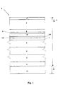
- a plate component 1 shows the structure of a plate component 1.
- a plate component 1 also referred to as a honeycomb sandwich structure, consists of a honeycomb core 2 and a plurality of cover layers 3, 4, 5, 6 and 7.
- the cover layers 3, 4, 5, 6 and 7 are in accordance with the intended use and the necessary ones Select strength in thickness and design.
- the cover layers 3 and 4 are provided as lower cover layers, the layer 3 closest to the honeycomb core 2 being a carbon fiber prepreg material layer and the layer 4 underneath being a glass fiber reinforced prepreg material layer ( gfk-pf-prepreg) 4.
- a carbon fiber-reinforced prepreg material layer (CFRP plate) and cover layers 6 and 7 made of prepreg layers, such as fiberglass-epoxy prepreg, are provided as the top cover layer 5.
- CFRP plate carbon fiber-reinforced prepreg material layer
- cover layers 6 and 7 made of prepreg layers, such as fiberglass-epoxy prepreg are provided as the top cover layer 5.
- Prepreg refers to fiber material pre-impregnated with curable synthetic resin.
- Such a panel component 1 for use as a floor panel has an essential advantage for use in an aircraft due to its lightness and strength. In certain areas of the aircraft floor, in particular in the door area of the aircraft, it is necessary to provide heating devices since, especially on long-haul flights at high altitudes, aircraft outer skin temperatures down to -55 ° C in the floor area can result in freezing temperatures down to -15 ° C.
- a film heater 8 is introduced between the upper cover layers 6 and 7.
- the foil heater 8 is preferably formed from Kapton / Cupron foil heating elements.
- Kapton is the carrier material for such heating foils
- Cupron (alloy) is a heating material.
- Manganin can be used as an alternative heating material.
- the heating elements for the foil heater 8 have a linear temperature coefficient and can achieve local individual performances in order to achieve the necessary homogeneous temperature distribution.
- the film heating elements 8 are arranged and glued between the fiberglass epoxy prepreg layers 6 and 7 by means of epoxy resin layers (epoxy film adhesive) 9 and 10.
- the component plate 1 contains as a top cover a heat-conducting cover plate 11 as protection against mechanical stress and for heat distribution.
- a relatively thin, approx. 0.5 mm thick surface-coated metal plate is provided, preferably made of aluminum.
- the aluminum plate 11 enables rapid heat transport and homogeneous heat distribution.
- the metal cover plate 11 is glued to the other layers as a composite.
- an electronic temperature control unit is provided, which uses a PTC sensor 12A to determine the temperature distribution in the plate component 1 and regulates the thermal output of the film heater 8 for a homogeneous temperature distribution. If this regulation fails, an overtemperature switch 12B with two switch-off stages is provided to prevent the plate 1 from overheating. When the top level is reached, for example at 80 ° C, the plate heating is switched off for as long as there is voltage.
- the lower stage of the overtemperature switch controls the film heater 8 at a certain temperature level.
- a bimetal switch can be used, the z. B. controls the heating circuit in a temperature range from 30 ° C to 60 ° C (with a certain tolerance of approx. +/- 5 ° C).
- the upper stage of the overtemperature switch 12B is thus provided as a safety shutdown in the event of overheating and is only used when the lower stage of the overtemperature switch 12B has also failed.
- the PTC sensor 12A and the overtemperature switch 12B are also integrated in the component plate 1. It is preferable to use film elements which have been introduced between the epoxy resin layer (epoxy film adhesive) 10 and the fiberglass-epoxy prepreg layer 6.
- the CFRP plates 3 and 5 and the metal cover plate 11 are electrically on Ground potential to ensure safe shutdown in the event of a short circuit, for example, if the plate is damaged. In addition, should electronic monitoring of the heating current in the temperature control unit be provided so that the circuit is interrupted in the event of a short circuit.
- the component plate 1 is produced as a composite of the various layers in an autoclave at the appropriate temperature and preferably under vacuum. With the production under vacuum one avoids air pockets in the component plate 1, which is disadvantageous for the application of the same with changing pressure conditions during the use of the aircraft.
- the strength of the component panel 1, which is necessary for use as an aircraft floor panel, is ensured by the structure with carbon fiber reinforced and glass fiber reinforced cover layers 3, 4, 5, 6 and 7, the honeycomb core 2 and the cover plate 11.
- Such a component plate 1 has a thickness of approximately 9.5 mm.
- An approximately 10 mm thick insulating layer 21, for example made of plastic foam, can be arranged below this composite in order to reduce heat losses.
- the composite building board 1 can be varied in structure and layer thickness.
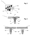
- FIG. 2 is a plan view of a section of an inventive Plate component 1 shown in the area of a cable connection.
- a bundle of cables 13 is connected to the heater foil 8 via individual lines (for example 14).
- a Connection to the measuring and switch elements is also provided. It a printed circuit can also be used, which is connected to lines of the Cable bundle 13 is connected.
- a connection to is also necessary Case ground (CASE GND) 14A, d. H. a connection to the aluminum plate 11.
- Das Cable bundle 13 is by means of a cable tie 13A on the holder 13B Component plate 1 attached.
- Fig. 3 is the side view of the area of the plate member 1 with the Cable bundle 13 can be seen.
- For the cable connection is in the plate 1
- Corresponding free space 15 is provided to manufacture the electrical Enable connections.
- a shrink tube 16 is called Protective measure pulled over the cable bundle 13.
- After completion of the Connections is the free space 15 and a transition area 17 between Outer surface of the plate 1 and cable bundle 13 with a waterproof potting Mistake.
- the use of epoxy resin is advantageous here. So that's one sufficient moisture tightness and skydrol resistance achieved.
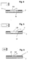
- Figs. 4 to 6 is the integration of the PTC sensor 12A and the Overtemperature switch 12B can be seen in the component plate 1.
- Fig. 4 shows the Floor recess 18 for the first stage of the overtemperature switch 12B and
- FIG. 5 shows the recess 19 for the second stage of the overtemperature switch 12B.
- a recess 20 is shown in the plate 1. This Recess 20 is provided for the PTC sensor 12A.
- the electronic components 12A and 12B are preferably each glued to the cover plate 11 and to the heating foil 8 connected. In all cases, after making a working Connection of the electrical components preferably with the recesses Epoxy resin can be cast.
Landscapes
- Engineering & Computer Science (AREA)
- Mechanical Engineering (AREA)
- Aviation & Aerospace Engineering (AREA)
- Pulmonology (AREA)
- General Health & Medical Sciences (AREA)
- Physics & Mathematics (AREA)
- Thermal Sciences (AREA)
- Chemical & Material Sciences (AREA)
- Combustion & Propulsion (AREA)
- Health & Medical Sciences (AREA)
- General Engineering & Computer Science (AREA)
- Central Heating Systems (AREA)
- Surface Heating Bodies (AREA)
- Laminated Bodies (AREA)
Abstract
Description

Als Alternativlösung wurden separat beheizbare Metallfußbodenplatten auf herkömmliche Fußbodenplatten aufgeschraubt. Auch eine solche Lösung ist mit einem hohen Gewicht sowie einem hohen Energieverbrauch verbunden.
- Fig. 1
- den Aufbau eines Plattenbauteils,
- Fig. 2
- das erfindungsgemäße Plattenbauteil im Bereich eines elektrischen Anschlußelementes in der Draufsicht,
- Fig. 3
- das elektrische Anschlußelement gemäß Fig. 2 in einer Seitenansicht und
- Fign. 4 bis 6
- die Aussparungen im Plattenbauteil für Sensor- und Schaltelemente.
Die Bauteilplatte 1 enthält als obere Abdeckung eine wärmeleitende Deckplatte 11 als Schutz gegenüber mechanischer Beanspruchung und zur Wärmeverteilung. Vorgesehen ist dafür eine relativ dünne, ca. 0,5 mm starke oberflächenvergütete Metallplatte, vorzugsweise aus dem Werkstoff Aluminium. Die Aluminiumplatte 11 ermöglicht einen schnellen Wärmetransport und eine homogene Wärmeverteilung. Die Metalldeckplatte 11 wird mit den anderen Schichten als Composite verklebt.
Zur Temperaturregelung an dem Plattenbauteil 1 ist eine elektronische Temperaturregeleinheit vorgesehen, die mittels eines PTC-Sensors 12A die Temperaturverteilung im Plattenbauteil 1 ermittelt und die Wärmeleistung des Folienheizers 8 für eine homogene Temperaturverteilung regelt. Bei Ausfall dieser Regelung ist zur Verhinderung einer Überhitzung der Platte 1 ein Übertemperaturschalter 12B mit zwei Abschaltstufen vorgesehen. Bei Erreichen der obersten Stufe, beispielsweise bei 80°C, wird die Plattenbeheizung solange abgeschaltet wie Spannung anliegt. Somit ist eine Überhitzung der Platte 1 ausgeschlossen und der entsprechende Folienheizer 8 ist ausgeschaltet. Die untere Stufe des Übertemperaturschalters regelt den Folienheizer 8 in einem bestimmten Temperaturniveau. Vorzugsweise kann ein Bimetall-Schalter verwendet werden, der z. B. in einem Temperaturbereich von 30°C bis 60°C (mit einer gewissen Toleranz von ca. +/- 5°C) den Heizkreis regelt. Die obere Stufe des Übertemperaturschalters 12B ist somit als Sicherheitsabschaltung bei einer Überhitzung vorgesehen und kommt erst zum Einsatz, wenn auch die untere Stufe des Übertemperaturschalters 12B ausgefallen ist.
Der PTC-Sensor 12A sowie der Übertemperaturschalter 12B sind ebenfalls in die Bauteilplatte 1 integriert. Vorzugsweise sind Folienelemente zu verwenden, die zwischen der Epoxidharzschicht (epoxy film adhesive) 10 und der Fiberglass-epoxy-prepreg-Lage 6 eingebracht wurden.
Für andere Einsatzzwecke mit anderen Festigkeitsanforderungen kann die Verbundbauplatte 1 im Aufbau und den Schichtdicken variiert werden.
Claims (11)
- Plattenbauteil, insbesondere für eine Fußbodenplatte in einem Flugzeug, wobei das Bauteil im wesentlichen aus mehreren Schichten aufgebaut ist und zumindest einen Wabenkern und mindestens eine untere und mindestens eine obere Deckschicht aufweist, wobei die Deckschichten aus GFK und/oder CFK-Lagen bestehen, dadurch gekennzeichnet, daß ein Folienheizer (8) zumindest bereichsweise in das Plattenbauteil (1) eingebracht ist und eine wärmeleitende obere Deckplatte (11) vorgesehen ist.
- Plattenbauteil nach Anspruch 1,
dadurch gekennzeichnet, daß
der Folienheizer (8) zwischen zwei oberen Deckschichten (6, 7) aus GFK-Lagen angeordnet ist und eine weitere obere Deckschicht (5) zwischen Wabenkern (6) und GFK-Lagen (6, 7) eine CFK-Lage bildet. - Plattenbauteil nach einem der Ansprüche 1 oder 2,
dadurch gekennzeichnet, daß
der Folienheizer (8) aus Kapton/Cupron (bzw. Manganin)-Folien-Heizelementen gebildet ist. - Plattenbauteil nach einem der Ansprüche 1 bis 3,
dadurch gekennzeichnet, daß
als wärmeleitende obere Deckplatte (11) eine Aluminiumplatte, die als Deckschicht mit den anderen Schichten verklebt wird, vorgesehen ist. - Plattenbauteil nach einem der Ansprüche 1 bis 4,
dadurch gekennzeichnet, daß
eine Temperaturregeleinheit zur Regelung des Folienheizers (8) vorgesehen ist, wobei ein PTC-Sensor (12A) sowie mindestens ein Übertemperaturschalter (12B) in das Plattenbauteil (1) integriert ist. - Plattenbauteil nach Anspruch 5,
dadurch gekennzeichnet, daß
der Übertemperaturschalter (12B) zweistufig ausgebildet ist, wobei eine erste Abschaltstufe innerhalb eines vorbestimmten Temperaturbereiches Mittel zum Regeln aufweist und eine zweite Abschaltstufe bei Erreichen einer Überhitzungstemperatur abschaltet. - Plattenbauteil nach einem der Ansprüche 1 bis 6,
dadurch gekennzeichnet, daß
Aussparungen (15, 18, 19, 20) im Plattenbauteil (1) zur Aufnahme zumindest der Anschlußleitungen (14) des Kabelbündels (13), des PTC-Sensors (12A) sowie des Übertemperaturschalters (12B) vorgesehen sind. - Plattenbauteil nach einem der Ansprüche 1 bis 7,
dadurch gekennzeichnet, daß
die vorhandenen Aussparungen (15, 18, 19, 20) am Plattenbauteil (1) und/oder Kabelanschlußstellen (17) mit einem wasserdichten Verguß, vorzugsweise Epoxidharz, versehen sind. - Plattenbauteil nach einem der Ansprüche 1 bis 8,
dadurch gekennzeichnet, daß
die CFK-Lagen (3, 5) und/oder die Metalldeckplatte (11) elektrisch auf Massepotential gelegt werden. - Plattenbauteil nach einem der Ansprüche 1 bis 9,
dadurch gekennzeichnet, daß
die Temperaturregeleinheit weiterhin ein Mittel zur Überwachung des Heizstromes, die im Kurzschlußfall abschalten, aufweist. - Plattenbauteil nach einem der Ansprüche 1 bis 10,
dadurch gekennzeichnet, daß
eine Isolierschicht (21) als weitere Lage im Plattenbauteilverbund, vorzugsweise unterhalb der Sandwichstruktur vorgesehen ist.
Applications Claiming Priority (2)
| Application Number | Priority Date | Filing Date | Title |
|---|---|---|---|
| DE19918736A DE19918736C2 (de) | 1999-04-24 | 1999-04-24 | Plattenbauteil, insbesondere für eine Fußbodenplatte in einem Flugzeug |
| DE19918736 | 1999-04-24 |
Publications (3)
| Publication Number | Publication Date |
|---|---|
| EP1046576A2 true EP1046576A2 (de) | 2000-10-25 |
| EP1046576A3 EP1046576A3 (de) | 2000-11-02 |
| EP1046576B1 EP1046576B1 (de) | 2006-10-04 |
Family
ID=7905789
Family Applications (1)
| Application Number | Title | Priority Date | Filing Date |
|---|---|---|---|
| EP00106295A Expired - Lifetime EP1046576B1 (de) | 1999-04-24 | 2000-03-23 | Plattenbauteil, insbesondere für eine Fussbodenplatte in einem Flugzeug |
Country Status (4)
| Country | Link |
|---|---|
| EP (1) | EP1046576B1 (de) |
| JP (1) | JP2000356358A (de) |
| DE (2) | DE19918736C2 (de) |
| ES (1) | ES2272210T3 (de) |
Cited By (9)
| Publication number | Priority date | Publication date | Assignee | Title |
|---|---|---|---|---|
| WO2001017850A1 (en) * | 1999-09-10 | 2001-03-15 | Bfgoodrich Company | Aircraft heated floor panel |
| GB2423224A (en) * | 2004-12-23 | 2006-08-16 | Goodrich Corp | Heated floor panel for aircraft |
| US8371526B2 (en) | 2006-01-12 | 2013-02-12 | Goodrich Corporation | Aircraft heater floor panel |
| EP1588941A3 (de) * | 2004-04-24 | 2013-09-18 | ESW GmbH | Vorrichtung zur Beheizung von Verriegelungselementen in Flugzeugen |
| CN105564630A (zh) * | 2014-10-29 | 2016-05-11 | 空中客车运作有限责任公司 | 一种用于飞机的地板以及具备这种地板的飞机 |
| EP3095690A3 (de) * | 2015-05-21 | 2017-02-08 | Goodrich Corporation | Flugzeugdeck |
| US9567754B2 (en) | 2012-08-21 | 2017-02-14 | Milwaukee Composites, Inc. | Flooring assembly with heat dissipation layer |
| EP3339013A1 (de) * | 2016-12-20 | 2018-06-27 | Goodrich Corporation | Beheizte bodenplatten mit wärmeleitenden und elektrisch isolierendem gewebe |
| WO2020187441A1 (de) * | 2019-03-15 | 2020-09-24 | Lufthansa Technik Ag | Heizmatte zur verwendung in einem fussbodenaufbau, fussbodenaufbau und verfahren zu dessen herstellung |
Families Citing this family (19)
| Publication number | Priority date | Publication date | Assignee | Title |
|---|---|---|---|---|
| DE20213020U1 (de) * | 2002-08-24 | 2004-01-15 | Westag & Getalit Ag | Selbsttragende Verbundplatte |
| DE10332052A1 (de) | 2003-07-15 | 2005-02-03 | Heinrich Strunz Gmbh | Verfahren zur Herstellung eines Laminats, Vorrichtung zum Durchführen des Verfahrens und erhaltenes Laminat |
| DE10361655B4 (de) | 2003-12-30 | 2007-10-04 | Airbus Deutschland Gmbh | Vorrichtung und Verfahren zur Fußbodenheizung in einem Flugzeug |
| DE102004001080A1 (de) | 2004-01-05 | 2005-08-04 | Airbus Deutschland Gmbh | Anordnung zur Innenverkleidung einer Passagierkabine eines Flugzeuges |
| DE102006012647B4 (de) * | 2006-03-20 | 2008-01-31 | Airbus Deutschland Gmbh | Heizungssystem und Bauteil mit einem derartigen Heizungssystem |
| US8630534B2 (en) | 2006-03-20 | 2014-01-14 | Airbus Operations Gmbh | Heating system and component with such a heating system |
| DE102007062082A1 (de) * | 2007-12-21 | 2009-07-23 | Airbus Deutschland Gmbh | Kernverbundstruktur |
| JP2013511021A (ja) * | 2009-11-13 | 2013-03-28 | アールティーアール テクノロジーズ,インコーポレイテッド | 多層構造加熱パネル |
| DE102010046079A1 (de) | 2010-09-20 | 2012-03-22 | Forster Smt Gmbh | Fußbodenaufbau für Schienenfahrzeuge |
| DE102011101356A1 (de) | 2011-05-12 | 2012-11-15 | Airbus Operations Gmbh | Flächenheizsystem und Fahrzeug mit einem Flächenheizsystem |
| DE102015005945B3 (de) * | 2015-05-12 | 2016-08-11 | Esw Gmbh | Bodenelement für ein Flugzeug, Verfahren zum Betreiben eines Bodenelements für ein Flugzeug, Heizsystem für ein Flugzeug und Verfahren zum Herstellen eines Bodenelements für ein Flugzeug |
| DE102016221268B3 (de) * | 2016-10-28 | 2018-02-08 | Airbus Defence and Space GmbH | Kabinenstrukturbauteil, Verfahren zum Herstellen eines Kabinenstrukturbauteils, Kabinenanordnung und Verkehrsmittel |
| DE102017004106A1 (de) | 2017-04-30 | 2018-10-31 | Neotech AMT GmbH | Verbundwerkstoff in Sandwichstruktur mit auf mindestens einer Deckschicht angeordneten gedruckten Strukturen und/oder Schaltungen mit Anschlussmittel und Herstellungsverfahren hierzu |
| DE102018002917A1 (de) | 2018-04-10 | 2019-10-10 | Airbus Operations Gmbh | Beheizbare Fußbodenplatte und Fußbodenheizsystem für ein Flugzeug |
| BR122023020216A2 (pt) * | 2018-05-03 | 2024-01-16 | Qarbon Aerospace (Foundation), Llc | Aeroestrutura |
| US11040765B2 (en) * | 2018-06-27 | 2021-06-22 | Goodrich Corporation | Advanced composite heated floor panel |
| DE102018132123A1 (de) * | 2018-09-14 | 2020-03-19 | Elbe Flugzeugwerke Gmbh | Fußbodensystem mit Heizeinheit |
| DE102018009218B4 (de) | 2018-11-23 | 2025-04-10 | Airbus Operations Gmbh | Verkleidungselement mit Heizschicht in Sandwichbauweise |
| WO2020108724A1 (de) * | 2018-11-26 | 2020-06-04 | Michael Plasch | Modulares plattenelement zum erstellen einer wandheizung und system zum modularen erstellen einer wand aus wandheizungselementen |
Citations (1)
| Publication number | Priority date | Publication date | Assignee | Title |
|---|---|---|---|---|
| DE3922465A1 (de) | 1988-07-08 | 1990-01-11 | Nippon Basic Technology Lab | Elektrische heizvorrichtung fuer bodenbelaege und dergleichen und bodenbelag mit eingebetteter elektrischer heizvorrichtung |
Family Cites Families (16)
| Publication number | Priority date | Publication date | Assignee | Title |
|---|---|---|---|---|
| US3697728A (en) * | 1968-12-13 | 1972-10-10 | Air Plastic Service Gmbh | Heating devices |
| JPS54114338U (de) * | 1978-01-23 | 1979-08-11 | ||
| JPS5758290U (de) * | 1980-09-25 | 1982-04-06 | ||
| JPH0129709Y2 (de) * | 1981-06-15 | 1989-09-11 | ||
| JPS5884825A (ja) * | 1981-11-13 | 1983-05-21 | Toho Rayon Co Ltd | プリプレグ |
| WO1984004727A1 (en) * | 1983-05-27 | 1984-12-06 | Boeing Co | Lightweight, fire-retardant structural panel |
| DE3342755A1 (de) * | 1983-11-25 | 1985-06-05 | Reinhard 8088 Eching Ursprung | Heizelement fuer waermegeraete, verfahren zu dessen herstellung und heisskleber-pistole mit heizelement |
| JPH0116171Y2 (de) * | 1985-09-12 | 1989-05-12 | ||
| JPS63309433A (ja) * | 1987-06-10 | 1988-12-16 | Fuji Kiko Kk | 異方向多層ハニカムコア |
| JPH01243389A (ja) * | 1988-03-25 | 1989-09-28 | Furukawa Electric Co Ltd:The | 床暖房パネル |
| JPH0731052Y2 (ja) * | 1989-03-13 | 1995-07-19 | 三菱化学エムケーブイ株式会社 | 床暖房用パネルヒータ |
| JP2599887Y2 (ja) * | 1992-01-07 | 1999-09-20 | 菱有工業株式会社 | パネルヒーター |
| JPH0564624U (ja) * | 1992-01-27 | 1993-08-27 | 松下電工株式会社 | 床暖房用ヒーター |
| JPH0646210U (ja) * | 1992-11-18 | 1994-06-24 | 日本高圧電気株式会社 | 床暖房用セラミックヒーター |
| JPH06342686A (ja) * | 1993-06-01 | 1994-12-13 | Matsushita Electric Ind Co Ltd | 電気発熱装置 |
| JPH0732518A (ja) * | 1993-07-16 | 1995-02-03 | Dairin Shoji:Kk | 建築用複合建材 |
-
1999
- 1999-04-24 DE DE19918736A patent/DE19918736C2/de not_active Expired - Fee Related
-
2000
- 2000-03-23 EP EP00106295A patent/EP1046576B1/de not_active Expired - Lifetime
- 2000-03-23 DE DE50013535T patent/DE50013535D1/de not_active Expired - Lifetime
- 2000-03-23 ES ES00106295T patent/ES2272210T3/es not_active Expired - Lifetime
- 2000-04-21 JP JP2000121242A patent/JP2000356358A/ja active Pending
Patent Citations (1)
| Publication number | Priority date | Publication date | Assignee | Title |
|---|---|---|---|---|
| DE3922465A1 (de) | 1988-07-08 | 1990-01-11 | Nippon Basic Technology Lab | Elektrische heizvorrichtung fuer bodenbelaege und dergleichen und bodenbelag mit eingebetteter elektrischer heizvorrichtung |
Non-Patent Citations (1)
| Title |
|---|
| FLIGHT INTERNATIONAL, 17 April 1982 (1982-04-17), pages 988 - 989 |
Cited By (15)
| Publication number | Priority date | Publication date | Assignee | Title |
|---|---|---|---|---|
| US6834159B1 (en) | 1999-09-10 | 2004-12-21 | Goodrich Corporation | Aircraft heated floor panel |
| WO2001017850A1 (en) * | 1999-09-10 | 2001-03-15 | Bfgoodrich Company | Aircraft heated floor panel |
| EP1588941A3 (de) * | 2004-04-24 | 2013-09-18 | ESW GmbH | Vorrichtung zur Beheizung von Verriegelungselementen in Flugzeugen |
| GB2423224A (en) * | 2004-12-23 | 2006-08-16 | Goodrich Corp | Heated floor panel for aircraft |
| GB2423224B (en) * | 2004-12-23 | 2008-04-02 | Goodrich Corp | Aircraft floor panel |
| US8371526B2 (en) | 2006-01-12 | 2013-02-12 | Goodrich Corporation | Aircraft heater floor panel |
| US9567754B2 (en) | 2012-08-21 | 2017-02-14 | Milwaukee Composites, Inc. | Flooring assembly with heat dissipation layer |
| CN105564630A (zh) * | 2014-10-29 | 2016-05-11 | 空中客车运作有限责任公司 | 一种用于飞机的地板以及具备这种地板的飞机 |
| CN105564630B (zh) * | 2014-10-29 | 2018-04-27 | 空中客车运作有限责任公司 | 一种用于飞机的地板以及具备这种地板的飞机 |
| EP3095690A3 (de) * | 2015-05-21 | 2017-02-08 | Goodrich Corporation | Flugzeugdeck |
| US10279886B2 (en) | 2015-05-21 | 2019-05-07 | Goodrich Corporation | Aircraft floor panel |
| EP3339013A1 (de) * | 2016-12-20 | 2018-06-27 | Goodrich Corporation | Beheizte bodenplatten mit wärmeleitenden und elektrisch isolierendem gewebe |
| US10425989B2 (en) | 2016-12-20 | 2019-09-24 | Goodrich Corporation | Heated floor panels with thermally conductive and electrically insulating fabric |
| WO2020187441A1 (de) * | 2019-03-15 | 2020-09-24 | Lufthansa Technik Ag | Heizmatte zur verwendung in einem fussbodenaufbau, fussbodenaufbau und verfahren zu dessen herstellung |
| US12287100B2 (en) | 2019-03-15 | 2025-04-29 | Lufthansa Technik AG; | Heating mat for use in a floor structure, floor structure, and method for producing same |
Also Published As
| Publication number | Publication date |
|---|---|
| DE19918736C2 (de) | 2002-12-05 |
| DE50013535D1 (de) | 2006-11-16 |
| ES2272210T3 (es) | 2007-05-01 |
| EP1046576A3 (de) | 2000-11-02 |
| DE19918736A1 (de) | 2000-11-02 |
| JP2000356358A (ja) | 2000-12-26 |
| EP1046576B1 (de) | 2006-10-04 |
Similar Documents
| Publication | Publication Date | Title |
|---|---|---|
| DE19918736C2 (de) | Plattenbauteil, insbesondere für eine Fußbodenplatte in einem Flugzeug | |
| EP3449689B1 (de) | Heizvorrichtung und verfahren zum herstellen derselben | |
| DE60031864T2 (de) | Geheitzte flugzeugfussbodenplatte | |
| DE69327373T2 (de) | Innere Schicht einer Schutsumkehrvorrichtung aus nichtmetallischen, wärmeleitender Honigwabenstruktur | |
| DE69101703T2 (de) | Elektrisch leitendes laminat für temperaturregelung von oberflächen. | |
| DE60010951T2 (de) | Verfahren für die Simulation der äusseren Wärmeströme, die von den Abstrahlelementen eines Raumfahrzeuges während des Fluges absorbiert werden, und Raumfahrzeug für die Durchführung dieses Verfahrens | |
| EP2602455A1 (de) | Windenergieanlagenrotorblatt mit einem elektrischen Heizelement | |
| DE102014206861A1 (de) | Temperiervorrichtung für eine elektrische Energieversorgungseinheit | |
| WO2012159608A2 (de) | Verbundstruktur mit eisschutzvorrichtung sowie herstellverfahren | |
| EP1168463A1 (de) | Faserverbundwerkstoff mit darin integriertem piezoelektrischem Sensor oder Aktor | |
| DE2153434B2 (de) | Befestigung von erosionsschutzkanten an flugzeugprofilen | |
| DE3015998C2 (de) | Anordnung zur Beheizung großflächiger Laminatformkörper | |
| DE102016221268B3 (de) | Kabinenstrukturbauteil, Verfahren zum Herstellen eines Kabinenstrukturbauteils, Kabinenanordnung und Verkehrsmittel | |
| DE102016117916B4 (de) | Heizeinrichtung, Rotorblatt mit solch einer Heizeinrichtung und Windenergieanlage mit solch einem Rotorblatt sowie Verfahren zur Herstellung solch einer Heizeinrichtung | |
| EP3884155A1 (de) | Rotorblatt einer windenergieanlage mit einer isolatorlage und einer schutzlage | |
| EP2617080B1 (de) | Batteriegehäuse, batterie mit batteriegehäuse und kraftfahrzeug mit einer entsprechenden batterie | |
| EP1902944A2 (de) | Schiffsantrieb | |
| DE102018009218B4 (de) | Verkleidungselement mit Heizschicht in Sandwichbauweise | |
| DE2559099A1 (de) | Leichtgewichtiges heizgewebe | |
| DE102021105409A1 (de) | Brandfeste Sandwichstruktur | |
| EP3938715B1 (de) | Heizmatte zur verwendung in einem fussbodenaufbau, fussbodenaufbau und verfahren zu dessen herstellung | |
| DE2628731A1 (de) | Elektrisches widerstands-heizelement, insbesondere zur verwendung an flugzeugprofilen oder hubschrauberrotorblaettern als bestandteil einer enteisungsanlage fuer flugzeuge bzw. hubschrauber | |
| DE102004020662B3 (de) | Vorrichtung zur Beheizung von Verriegelungselementen in Flugzeugen | |
| DE102014111926A1 (de) | Dachelement | |
| DE102021207802A1 (de) | Gehäuseelement eines Batteriemoduls und Verfahren zur Herstellung eines solchen |
Legal Events
| Date | Code | Title | Description |
|---|---|---|---|
| PUAI | Public reference made under article 153(3) epc to a published international application that has entered the european phase |
Free format text: ORIGINAL CODE: 0009012 |
|
| PUAL | Search report despatched |
Free format text: ORIGINAL CODE: 0009013 |
|
| AK | Designated contracting states |
Kind code of ref document: A2 Designated state(s): DE ES FR GB NL |
|
| AX | Request for extension of the european patent |
Free format text: AL;LT;LV;MK;RO;SI |
|
| AK | Designated contracting states |
Kind code of ref document: A3 Designated state(s): AT BE CH CY DE DK ES FI FR GB GR IE IT LI LU MC NL PT SE |
|
| AX | Request for extension of the european patent |
Free format text: AL;LT;LV;MK;RO;SI |
|
| RAP1 | Party data changed (applicant data changed or rights of an application transferred) |
Owner name: EADS AIRBUS GMBH |
|
| 17P | Request for examination filed |
Effective date: 20001016 |
|
| AKX | Designation fees paid |
Free format text: DE ES FR GB NL |
|
| RAP1 | Party data changed (applicant data changed or rights of an application transferred) |
Owner name: AIRBUS DEUTSCHLAND GMBH |
|
| 17Q | First examination report despatched |
Effective date: 20050110 |
|
| GRAP | Despatch of communication of intention to grant a patent |
Free format text: ORIGINAL CODE: EPIDOSNIGR1 |
|
| RIC1 | Information provided on ipc code assigned before grant |
Ipc: H05B 3/26 20060101ALI20060322BHEP Ipc: B64C 1/40 20060101ALI20060322BHEP Ipc: F24D 13/02 20060101ALI20060322BHEP Ipc: B64C 1/18 20060101AFI20060322BHEP |
|
| GRAS | Grant fee paid |
Free format text: ORIGINAL CODE: EPIDOSNIGR3 |
|
| GRAA | (expected) grant |
Free format text: ORIGINAL CODE: 0009210 |
|
| AK | Designated contracting states |
Kind code of ref document: B1 Designated state(s): DE ES FR GB NL |
|
| PG25 | Lapsed in a contracting state [announced via postgrant information from national office to epo] |
Ref country code: NL Free format text: LAPSE BECAUSE OF FAILURE TO SUBMIT A TRANSLATION OF THE DESCRIPTION OR TO PAY THE FEE WITHIN THE PRESCRIBED TIME-LIMIT Effective date: 20061004 |
|
| REG | Reference to a national code |
Ref country code: GB Ref legal event code: FG4D Free format text: NOT ENGLISH |
|
| REF | Corresponds to: |
Ref document number: 50013535 Country of ref document: DE Date of ref document: 20061116 Kind code of ref document: P |
|
| GBT | Gb: translation of ep patent filed (gb section 77(6)(a)/1977) |
Effective date: 20061221 |
|
| NLV1 | Nl: lapsed or annulled due to failure to fulfill the requirements of art. 29p and 29m of the patents act | ||
| ET | Fr: translation filed | ||
| REG | Reference to a national code |
Ref country code: ES Ref legal event code: FG2A Ref document number: 2272210 Country of ref document: ES Kind code of ref document: T3 |
|
| PLBE | No opposition filed within time limit |
Free format text: ORIGINAL CODE: 0009261 |
|
| STAA | Information on the status of an ep patent application or granted ep patent |
Free format text: STATUS: NO OPPOSITION FILED WITHIN TIME LIMIT |
|
| 26N | No opposition filed |
Effective date: 20070705 |
|
| REG | Reference to a national code |
Ref country code: ES Ref legal event code: PC2A Owner name: AIRBUS OPERATIONS GMBH Effective date: 20110930 |
|
| REG | Reference to a national code |
Ref country code: FR Ref legal event code: CD Owner name: AIRBUS OPERATIONS GMBH Effective date: 20111118 |
|
| REG | Reference to a national code |
Ref country code: FR Ref legal event code: PLFP Year of fee payment: 17 |
|
| PGFP | Annual fee paid to national office [announced via postgrant information from national office to epo] |
Ref country code: ES Payment date: 20160309 Year of fee payment: 17 |
|
| REG | Reference to a national code |
Ref country code: FR Ref legal event code: PLFP Year of fee payment: 18 |
|
| REG | Reference to a national code |
Ref country code: FR Ref legal event code: PLFP Year of fee payment: 19 |
|
| REG | Reference to a national code |
Ref country code: ES Ref legal event code: FD2A Effective date: 20180629 |
|
| PG25 | Lapsed in a contracting state [announced via postgrant information from national office to epo] |
Ref country code: ES Free format text: LAPSE BECAUSE OF NON-PAYMENT OF DUE FEES Effective date: 20170324 |
|
| PGFP | Annual fee paid to national office [announced via postgrant information from national office to epo] |
Ref country code: GB Payment date: 20190320 Year of fee payment: 20 Ref country code: FR Payment date: 20190322 Year of fee payment: 20 Ref country code: DE Payment date: 20190321 Year of fee payment: 20 |
|
| REG | Reference to a national code |
Ref country code: DE Ref legal event code: R071 Ref document number: 50013535 Country of ref document: DE |
|
| REG | Reference to a national code |
Ref country code: GB Ref legal event code: PE20 Expiry date: 20200322 |
|
| PG25 | Lapsed in a contracting state [announced via postgrant information from national office to epo] |
Ref country code: GB Free format text: LAPSE BECAUSE OF EXPIRATION OF PROTECTION Effective date: 20200322 |