EP1046732A1 - Zange für Baumwollkämmaschinen - Google Patents
Zange für Baumwollkämmaschinen Download PDFInfo
- Publication number
- EP1046732A1 EP1046732A1 EP19990890120 EP99890120A EP1046732A1 EP 1046732 A1 EP1046732 A1 EP 1046732A1 EP 19990890120 EP19990890120 EP 19990890120 EP 99890120 A EP99890120 A EP 99890120A EP 1046732 A1 EP1046732 A1 EP 1046732A1
- Authority
- EP
- European Patent Office
- Prior art keywords
- nipper
- ratchet
- feed
- ratchet gear
- lever
- Prior art date
- Legal status (The legal status is an assumption and is not a legal conclusion. Google has not performed a legal analysis and makes no representation as to the accuracy of the status listed.)
- Withdrawn
Links
- 241000347389 Serranus cabrilla Species 0.000 title abstract description 16
- 229920000742 Cotton Polymers 0.000 title description 3
- 230000007246 mechanism Effects 0.000 abstract description 10
- 230000008859 change Effects 0.000 abstract description 4
- 230000009471 action Effects 0.000 abstract description 2
- 230000003213 activating effect Effects 0.000 abstract description 2
- 238000004140 cleaning Methods 0.000 abstract description 2
- 230000006978 adaptation Effects 0.000 description 3
- 239000000463 material Substances 0.000 description 3
- 241000219146 Gossypium Species 0.000 description 2
- 240000000047 Gossypium barbadense Species 0.000 description 2
- 235000009429 Gossypium barbadense Nutrition 0.000 description 2
- 238000000034 method Methods 0.000 description 2
- 230000008569 process Effects 0.000 description 2
- 241000364051 Pima Species 0.000 description 1
- 238000013459 approach Methods 0.000 description 1
- 230000008901 benefit Effects 0.000 description 1
- 230000001627 detrimental effect Effects 0.000 description 1
- 238000000605 extraction Methods 0.000 description 1
- 239000000835 fiber Substances 0.000 description 1
- 230000005484 gravity Effects 0.000 description 1
- 238000009434 installation Methods 0.000 description 1
- 238000004519 manufacturing process Methods 0.000 description 1
- 239000004753 textile Substances 0.000 description 1
- 210000002268 wool Anatomy 0.000 description 1
Images



Classifications
-
- D—TEXTILES; PAPER
- D01—NATURAL OR MAN-MADE THREADS OR FIBRES; SPINNING
- D01G—PRELIMINARY TREATMENT OF FIBRES, e.g. FOR SPINNING
- D01G19/00—Combing machines
- D01G19/06—Details
- D01G19/26—Driving arrangements
Definitions
- This invention relates to a nipper of a combing machine.
- the nipper of course should be advantageous for newly manufactured combers as well.
- a nipper of a combing machine comprising a lower nipper with a nipper plate and an upper nipper with a knife, jointed on said lower nipper, a feed roll with a ratchet gear arranged on said lower nipper, a backward feed ratchet lever jointed on said upper nipper, a spring forcing said backward feed ratchet lever against said ratchet gear, first guide means arranged on said lower nipper, second guide means arranged on said backward feed ratchet lever, wherein said first guide means and said second guide means co-operate during opening and closing movement of said upper nipper, restricting upward movement of said backward feed ratchet lever during opening movement and guiding said backward feed ratchet lever to pass said ratchet gear during closing movement, wherein said first guide means and said second guide means being out of contact in the closed operating position of said upper nipper.
- a nipper of a combing machine comprising a lower nipper with a nipper plate and an upper nipper with a knife, jointed on said lower nipper, a feed roll with a ratchet gear arranged on said lower nipper, and a forward feed ratchet lever located above said ratchet gear and engaging said ratchet gear.
- the nipper of the present invention shifts the lap feed roll forward in the direction of the knife and closer to the detaching rolls.
- the clamping distance between the feed roll and the rear detaching rolls is advantageously adapted to the reduced staple length.
- a ratchet mechanism for activating the feed roll is used which takes into account the limited availability of space.
- the nipper comprises said backward feed ratchet lever and said forward feed ratchet lever, wherein said ratchet gear is engaged by either said backward feed ratchet lever or said forward feed ratchet lever.
- the ratchet gear is of cylindrical shape, one part at one axial end of the cylindrical surface being provided with teeth for engagement with one ratchet lever and the other part on the other axial end being smooth defining a sliding surface for the other ratchet lever.
- the knife may be opened and closed again without any further attention of the operator to the ratchet mechanism. Doing this the feed roll can be taken out and the change from one kind of feed operation to another kind is possible in a simple and straightforward manner.
- the inventive mechanism might be adapted to equipment already in use or to newly manufactured ones.
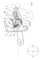
- Fig. 1 shows a side view of a nipper and a ratchet mechanism which drives a feed roll 5.
- the nipper comprises a lower nipper with a nipper plate 1 and an upper nipper with a knife 2 pivotable about axis 23 on the lower nipper.
- the lower nipper is guided by a front support 3 and driven by a rear support 24 oscillating about axis 18 along line 19 and arrow 20.
- Rear support 24 further is connected through a spring 25 to the upper nipper.
- the spring 25 is connected to the upper nipper by a rod 29 and a bolt passing through bore 22 at the backward end of upper nipper.
- the other end of the spring 25 is connected to the rear support 24.
- the rod 29 is guided in a slide 27, whereas said slide 27 is attached to rear support 24 by a rigid tube 28.
- Fig. 1 shows the nipper in the most forward position. In this position the knife 2 is opened. When the nipper moves backward the knife 2 will be closed and thus clamping the lap to be processed. When the nipper swings back and the detaching rolls 4 move forward the lap is detached.
- a feed roll 5 moves the lap (not shown) passing between feed roll 5 and nipper plate 1 forward in a discontinuous way.
- Backward feed or feeding while detaching means that the feed roll 5 is turning while the nipper swings back and the knife 2 is closing.
- Forward feed or feeding before detaching means that the feed roll 5 is turning while the nipper swings forward and the knife 2 is opening.
- a backward feed ratchet gear 6 Coaxially attached to the feed roll 5 is a backward feed ratchet gear 6.
- the ratchet gear 6 is activated by a backward feed ratchet lever 7.
- the backward feed ratchet lever 7 is pivoted by means of a bolt 8 to the upper nipper with knife 2 and thus follows the movement of said knife 2.
- a spring 9 forces the ratchet lever 7 towards the ratchet gear 6.
- knife 2 is closing the backward feed ratchet lever 7 turns the ratchet gear 6 forward by one tooth. This gives the feed roll 5 a turn of defined angle thus delivering a defined length of the lap.
- the ratchet gear 6 is interchangeable with ratchet gears of different number of teeth thus allowing different amounts of lap feed.
- the backward feed ratchet lever 7 comprises at its bottom end a pin 10.
- a guide plate 11 is attached to the lower nipper with nipper plate 1. During normal operation of combing the pin 10 is not in contact with the guide plate 11.
- a spiral spring 12 comprises at one end an extension 13. This extension 13 is forced by spring 12 towards the feed roll 5 thus holding the feed roll 5 in place and clamping the lap (not shown). The other end of spiral spring 12 is connected to the upper nipper.
- the system further incorporates a forward feed ratchet lever 16 pivoted by the bolt 8 to the upper nipper and positioned above ratchet gear 6.
- the forward feed ratchet lever 16 is held on ratchet gear 6 by gravity.
- This forward feed ratchet lever 16 may act on a ratchet gear 17 similar to its counterpart backward feed ratchet lever 7. Anyhow those two levers 7, 16 are not in engagement with ratchet gear 6 at the same time. This is accomplished by exchange of ratchet gear 6, as is explained later with reference to Fig. 3 and 4.
- Fig. 2 shows the same side view as Fig. 1 but the upper nipper with knife 2 is now in an entirely opened position. This however is not a normal operating and combing position, respectively, but a service position.
- the spiral spring 12 with extension 13 is rotated through the action of a pin 15 engaging a bent end 14 of spiral spring 12 projecting from extension 13.
- Pin 15 is attached to the upper nipper with knife 2. While the upper nipper with knife 2 is opened pin 15 activates the spiral spring 12 in the manner shown in Fig. 2.
- Feed roll 5 with ratchet gear 6 may now be easily removed by an operator (not shown). This operation of removal of the feed roll 5 is advantageous for easy cleaning and maintaining the feed roll 5 and exchange of ratchet gear 6.
- the forward feed ratchet lever 16 is also lifted in the shown open position of the upper nipper.
- Fig. 3 is a top view of the backward feed ratchet gear 6.
- the backward feed ratchet gear 6 has teeth cut only partially as shown on its cylindrical surface. Therefore only the backward feed ratchet lever 7 can engage ratchet gear 6 while the forward feed ratchet lever 16 is in contact with the smooth cylindrical surface part. Therefore the forward feed ratchet lever 16 does not activate the backward feed ratchet gear 6 and might be omitted.
- Fig. 4 the backward feed ratchet gear 6 has been replaced by a forward feed ratchet gear 17. Now the situation is reversed.
- the forward feed ratchet gear 17 has teeth cut only partially on the other side of its cylindrical surface as shown. Therefore only the forward feed ratchet lever 16 actually can engage forward feed ratchet gear 17 while the backward feed ratchet lever 7 is in contact with the smooth cylindrical surface part. Therefore backward feed ratchet lever 7 does not activate the forward feed ratchet gear 17 and might be omitted.
- the ratchet gears 6 and 17 have an outer diameter of approximately 20 to 30 millimetres and approximately 12 to 18 teeth.
- the spring 9 acts with a force of approximately 1 Newton towards the ratchet lever 7.
Landscapes
- Engineering & Computer Science (AREA)
- Textile Engineering (AREA)
- Preliminary Treatment Of Fibers (AREA)
Priority Applications (1)
| Application Number | Priority Date | Filing Date | Title |
|---|---|---|---|
| EP19990890120 EP1046732A1 (de) | 1999-04-13 | 1999-04-13 | Zange für Baumwollkämmaschinen |
Applications Claiming Priority (1)
| Application Number | Priority Date | Filing Date | Title |
|---|---|---|---|
| EP19990890120 EP1046732A1 (de) | 1999-04-13 | 1999-04-13 | Zange für Baumwollkämmaschinen |
Publications (1)
| Publication Number | Publication Date |
|---|---|
| EP1046732A1 true EP1046732A1 (de) | 2000-10-25 |
Family
ID=8243974
Family Applications (1)
| Application Number | Title | Priority Date | Filing Date |
|---|---|---|---|
| EP19990890120 Withdrawn EP1046732A1 (de) | 1999-04-13 | 1999-04-13 | Zange für Baumwollkämmaschinen |
Country Status (1)
| Country | Link |
|---|---|
| EP (1) | EP1046732A1 (de) |
Cited By (2)
| Publication number | Priority date | Publication date | Assignee | Title |
|---|---|---|---|---|
| CN102330195A (zh) * | 2011-08-22 | 2012-01-25 | 山西鸿基科技股份有限公司 | 精梳机棉卷不粘卷喂入机构 |
| CN111850742A (zh) * | 2020-08-31 | 2020-10-30 | 济南永信新材料科技有限公司 | 提升纤维握持力度的梳理机延棉喂入装置 |
Citations (4)
| Publication number | Priority date | Publication date | Assignee | Title |
|---|---|---|---|---|
| FR1282002A (fr) * | 1960-11-28 | 1962-01-19 | Alsacienne Constr Meca | Dispositif de contrôle du mouvement alternatif de rotation d'un cylindre d'arrachage de peigneuse rectiligne |
| CH485873A (de) * | 1966-10-10 | 1970-02-15 | Maremont Corp | Kämmaschine |
| DE3336812A1 (de) * | 1982-12-16 | 1984-06-20 | Veb Kombinat Textima, Ddr 9010 Karl-Marx-Stadt | Speisewalzenantrieb fuer kaemmaschinen |
| JPH02169730A (ja) * | 1988-12-22 | 1990-06-29 | Tokyu Kk | コーマ機のラップ送り出し装置 |
-
1999
- 1999-04-13 EP EP19990890120 patent/EP1046732A1/de not_active Withdrawn
Patent Citations (4)
| Publication number | Priority date | Publication date | Assignee | Title |
|---|---|---|---|---|
| FR1282002A (fr) * | 1960-11-28 | 1962-01-19 | Alsacienne Constr Meca | Dispositif de contrôle du mouvement alternatif de rotation d'un cylindre d'arrachage de peigneuse rectiligne |
| CH485873A (de) * | 1966-10-10 | 1970-02-15 | Maremont Corp | Kämmaschine |
| DE3336812A1 (de) * | 1982-12-16 | 1984-06-20 | Veb Kombinat Textima, Ddr 9010 Karl-Marx-Stadt | Speisewalzenantrieb fuer kaemmaschinen |
| JPH02169730A (ja) * | 1988-12-22 | 1990-06-29 | Tokyu Kk | コーマ機のラップ送り出し装置 |
Non-Patent Citations (1)
| Title |
|---|
| PATENT ABSTRACTS OF JAPAN vol. 14, no. 435 (C - 0760) 18 September 1990 (1990-09-18) * |
Cited By (2)
| Publication number | Priority date | Publication date | Assignee | Title |
|---|---|---|---|---|
| CN102330195A (zh) * | 2011-08-22 | 2012-01-25 | 山西鸿基科技股份有限公司 | 精梳机棉卷不粘卷喂入机构 |
| CN111850742A (zh) * | 2020-08-31 | 2020-10-30 | 济南永信新材料科技有限公司 | 提升纤维握持力度的梳理机延棉喂入装置 |
Similar Documents
| Publication | Publication Date | Title |
|---|---|---|
| JP5313560B2 (ja) | 織物繊維を含む繊維束を繊維分類又は繊維選択するための、特にコーミングするための装置 | |
| EP1046732A1 (de) | Zange für Baumwollkämmaschinen | |
| US4222154A (en) | Fibre flock material feed apparatus for opening rolls | |
| CS9000652A2 (en) | Method and device for spinning mechanism spinning-in for break spinning | |
| CN113247337B (zh) | 捆扎机 | |
| US4069655A (en) | Open end spinning assembly with an opener roll | |
| CS214750B2 (en) | Facility for spinning over the yearn on the spindleless afterspinning machine | |
| US5044048A (en) | Combing machine | |
| EP2400048B1 (de) | Kämmmaschine | |
| US3400431A (en) | Comber nipper feed system | |
| JP2683928B2 (ja) | コーマ機のラップ送り出し装置 | |
| CH681629A5 (de) | ||
| US6591458B1 (en) | Top comb | |
| US4972667A (en) | Apparatus for and method of stopping fiber-material feed | |
| JPH04327221A (ja) | コーマ機のラップ送り出し方法 | |
| CN213681029U (zh) | 一种后罗拉锁罩及细纱断头粗纱停喂装置 | |
| CZ297410B6 (cs) | Podávací ústrojí pramene vláken pro rotorové doprádací zarízení | |
| DE102007019733A1 (de) | Offenend-Spinnvorrichtung mit einer Bremseinrichtung für eine Auflösewalze | |
| CN112111814B (zh) | 自由端纺纱装置的纤维条开松机构和开松机构的喂料板 | |
| JPH11189928A (ja) | 梳綿機の繊維剥離装置 | |
| US1197984A (en) | Cotton-comber. | |
| Auer | Combing Principles | |
| US1292717A (en) | Top-feed-roll holder for cotton-combers. | |
| JP7140541B2 (ja) | 綿繰り機 | |
| EP3865610A1 (de) | Finnisseur für spinnverfahren mit einer vorgarnwickelanordnung |
Legal Events
| Date | Code | Title | Description |
|---|---|---|---|
| PUAI | Public reference made under article 153(3) epc to a published international application that has entered the european phase |
Free format text: ORIGINAL CODE: 0009012 |
|
| AK | Designated contracting states |
Kind code of ref document: A1 Designated state(s): AT BE CH CY DE DK ES FI FR GB GR IE IT LI LU MC NL PT SE |
|
| AX | Request for extension of the european patent |
Free format text: AL;LT;LV;MK;RO;SI |
|
| AKX | Designation fees paid | ||
| STAA | Information on the status of an ep patent application or granted ep patent |
Free format text: STATUS: THE APPLICATION IS DEEMED TO BE WITHDRAWN |
|
| 18D | Application deemed to be withdrawn |
Effective date: 20010426 |
|
| REG | Reference to a national code |
Ref country code: DE Ref legal event code: 8566 |