EP1046810A2 - Dispositif de montage d'injecteurs de carburant - Google Patents
Dispositif de montage d'injecteurs de carburant Download PDFInfo
- Publication number
- EP1046810A2 EP1046810A2 EP00102276A EP00102276A EP1046810A2 EP 1046810 A2 EP1046810 A2 EP 1046810A2 EP 00102276 A EP00102276 A EP 00102276A EP 00102276 A EP00102276 A EP 00102276A EP 1046810 A2 EP1046810 A2 EP 1046810A2
- Authority
- EP
- European Patent Office
- Prior art keywords
- fuel injector
- fuel
- cup
- lip
- pair
- Prior art date
- Legal status (The legal status is an assumption and is not a legal conclusion. Google has not performed a legal analysis and makes no representation as to the accuracy of the status listed.)
- Granted
Links
Images

Classifications
-
- F—MECHANICAL ENGINEERING; LIGHTING; HEATING; WEAPONS; BLASTING
- F02—COMBUSTION ENGINES; HOT-GAS OR COMBUSTION-PRODUCT ENGINE PLANTS
- F02M—SUPPLYING COMBUSTION ENGINES IN GENERAL WITH COMBUSTIBLE MIXTURES OR CONSTITUENTS THEREOF
- F02M69/00—Low-pressure fuel-injection apparatus ; Apparatus with both continuous and intermittent injection; Apparatus injecting different types of fuel
- F02M69/46—Details, component parts or accessories not provided for in, or of interest apart from, the apparatus covered by groups F02M69/02 - F02M69/44
- F02M69/462—Arrangement of fuel conduits, e.g. with valves for maintaining pressure in the pipes after the engine being shut-down
- F02M69/465—Arrangement of fuel conduits, e.g. with valves for maintaining pressure in the pipes after the engine being shut-down of fuel rails
-
- F—MECHANICAL ENGINEERING; LIGHTING; HEATING; WEAPONS; BLASTING
- F02—COMBUSTION ENGINES; HOT-GAS OR COMBUSTION-PRODUCT ENGINE PLANTS
- F02M—SUPPLYING COMBUSTION ENGINES IN GENERAL WITH COMBUSTIBLE MIXTURES OR CONSTITUENTS THEREOF
- F02M61/00—Fuel-injectors not provided for in groups F02M39/00 - F02M57/00 or F02M67/00
- F02M61/14—Arrangements of injectors with respect to engines; Mounting of injectors
- F02M61/145—Arrangements of injectors with respect to engines; Mounting of injectors the injection nozzle opening into the air intake conduit
-
- F—MECHANICAL ENGINEERING; LIGHTING; HEATING; WEAPONS; BLASTING
- F02—COMBUSTION ENGINES; HOT-GAS OR COMBUSTION-PRODUCT ENGINE PLANTS
- F02M—SUPPLYING COMBUSTION ENGINES IN GENERAL WITH COMBUSTIBLE MIXTURES OR CONSTITUENTS THEREOF
- F02M69/00—Low-pressure fuel-injection apparatus ; Apparatus with both continuous and intermittent injection; Apparatus injecting different types of fuel
- F02M69/08—Low-pressure fuel-injection apparatus ; Apparatus with both continuous and intermittent injection; Apparatus injecting different types of fuel characterised by the fuel being carried by compressed air into main stream of combustion-air
-
- F—MECHANICAL ENGINEERING; LIGHTING; HEATING; WEAPONS; BLASTING
- F02—COMBUSTION ENGINES; HOT-GAS OR COMBUSTION-PRODUCT ENGINE PLANTS
- F02M—SUPPLYING COMBUSTION ENGINES IN GENERAL WITH COMBUSTIBLE MIXTURES OR CONSTITUENTS THEREOF
- F02M2200/00—Details of fuel-injection apparatus, not otherwise provided for
- F02M2200/85—Mounting of fuel injection apparatus
- F02M2200/853—Mounting of fuel injection apparatus involving use of quick-acting mechanism, e.g. clips
Definitions
- Particular fuel injection systems employ an air-assist system to encourage atomization of fuel that is metered out of a fuel injector into the air intake stream within an air induction device.
- the fuel injector needs to form operative seals with a plurality of structural members.
- the fuel injector needs to form at least one fuel seal and at least one atmosphere seal.
- the fuel seal being located between the fuel rail and the fuel injector.
- the atmosphere seal being located between the sub-atmospheric air in an air-assist passage of the air-assist system and the atmosphere air external to the air induction device.
- a known manner of forming the atmosphere seal is to provide a face seal on the portion of the fuel injector installed in an aperture in the air induction device.
- the face seal engages and mates with a surface within the aperture to form the required atmosphere seal when an axial load is applied to the fuel injector.
- fuel pressure is applied to the fuel injector, which axial moves the fuel injector.
- fuel injectors in known systems are positioned proximate the fuel rail without being secured to the fuel rail.
- the present invention provides a mounting arrangement having a fuel rail; a fuel injector cup connected to the fuel rail, the fuel injector cup having a fuel communication area defining a longitudinal axis, a fuel rail mounting section, and a retaining surface; a fuel injector including a fuel metering end and a fuel inlet end, the fuel inlet end being exposed to the communication area; and a fastener that secures the fuel injector to the fuel injector cup and allows the fuel injector to reciprocate along the longitudinal axis of the fuel injector cup.
- the fuel injector cup preferably, comprises a cylindrical tube with a fuel rail mounting section being located at a first end of the tube, and the retaining surface being located at a second end of the tube.
- the retaining surface preferably, comprises a lip located at the second end of cylindrical tube extending away from the longitudinal axis.
- he fuel injector comprises a housing having a retention groove.
- the retention groove preferably, comprises a channel that partially encircles the housing of the fuel injector.
- the fastener preferably, comprises a dip having a wall and a pair of legs projecting from the wall. The pair of legs straddles both the fuel injector cup and the fuel injector.
- Each leg has a tab and a window.
- the tab has a mating surface that engages the channel of the fuel injector housing.
- the mounting arrangement of the present invention also includes an air induction device having an aperture.
- the metering end of the fuel injector has a face seal that mates with the aperture when the fuel injector is located at one of the first position and the second position along the longitudinal axis.
- the mounting arrangement of the present invention preferably, comprises a production assembly having the clip installed by an automated process.
- the production assembly is capable of satisfying at least an appropriate assembly integrity test and environmental vibration test.
- the present invention also provides a mounting arrangement with a fuel rail; a plurality of fuel injector cups connected to the fuel rail, each of the fuel injector cups including a cylindrical tube defining a longitudinal axis, a fuel rail mounting section disposed at a first end of the tube, and a lip at a second end of the tube; a plurality of fuel injectors, each fuel injector corresponding to one of the plurality of fuel injector cups , each fuel injector having a housing including a fuel metering end, a fuel inlet end, and a retention groove, the fuel inlet end of the fuel injector being disposed within the cylindrical tube of the fuel injection cup; and a clip that engages both the lip of the fuel injector cup and the retention groove in the housing of the fuel injector to secure the fuel injector to the fuel injector cup and allow the fuel injector to reciprocate along the longitudinal axis extending through the cylindrical tube of the fuel injector cup.
- the present invention also provides a clip that secures a fuel injector to a fuel injector cup on a fuel rail.
- the clip comprises a wall having a first end and a second end; a first leg projecting from the first end of the wall, the first leg including a first tab and a first window; and a second leg projecting from the second end of the wall, the first leg and the second leg being substantially parallel, the second leg including a second tab and a second window.
- the first tab and the second tab of the clip have a corresponding mating surface configuration adapted to engage the retention groove in a housing of the fuel injector.
- the first window and the second window of the clip each have a substantially similar frame adapted to engage a lip of the fuel injector cup.
- Each of the frames has a pair of landing edges extending along the corresponding leg. The pair of landing edges on each of the frames is spaced so that engagement of one of the landing edges with the lip of the fuel injector cup is exclusive of engagement of the lip of the fuel injector cup with the other of the landing edges.
- the present invention also provides a method of mounting a fuel injector to a fuel injector cup on a fuel rail so that the fuel injector is secured to the fuel injector cup and the fuel injector can be positioned along a longitudinal axis defined by the fuel injector cup.
- the method comprises: providing a fuel rail with at least one fuel injector cup, the at least one fuel injector cup including a retaining surface; locating at least one fuel injector proximate the at least one fuel injector cup, the at least one fuel injector having a housing with a retention groove; and securing the at least one fuel injector to the at least one fuel injector cup with a fastener that engages both the retention surface of the fuel injector cup and the retention groove in the housing of the fuel injector.
- the method of the present invention also includes installing the clip with an automated process so that the at least one fuel rail, the at least one fuel injector, and the clip comprise a production assembly capable of satisfying at least an appropriate assembly integrity test and environmental vibration test.
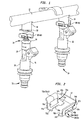
- Fig. 1 illustrates the mounting arrangement 10 of the present invention.
- the mounting arrangement 10 includes a fuel rail 12, fuel injector cups 14 connected to a fuel rail 12, a plurality fuel injectors 16, and a fastener 18 for each fuel injector 16.
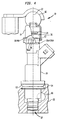
- Each of the fuel injector cups 14 has a fuel communication area 20 defining a longitudinal axis 22, illustrated in Figs.3 and 4.
- the fuel injector cup is a cylindrical tube 24.
- the cylindrical tube 24 is formed from stamped metal.
- a fuel rail mounting section 26 is located at a first end 24a of the cylindrical tube 24 that mounts the fuel injector cup 14 to the fuel rail 12.
- the fuel rail mounting section 26 is, preferably, brazed to the fuel rail 12, which is also metal.
- a retaining surface is located at a second end 24b of the cylindrical tube 24.
- the retaining surface preferably, comprises a lip 28 extending away from the longitudinal axis 22.
- Each of the fuel injectors 16 includes a housing 30 having a fuel metering end 32 and a fuel inlet end 34.
- the fuel inlet end 32 is exposed to the communication area 20.
- An O-ring 36 is positioned on the housing 30 proximate the fuel inlet end 34.
- the O-ring 36 forms a fuel tight seal with an inner surface 24c of the cylindrical tube 24 of the fuel injector cup 14.
- the housing 30 of the fuel injector 16 is provided with a retention groove.
- the retention groove is a channel 38 that partially encircles the housing 30 of the fuel injector 16.
- the channel includes a first end 38a and a second end 38b.
- Each fastener 18 secures a fuel injector 16 to a fuel injector cup 14 and allows the fuel injector 16 to reciprocate along the longitudinal axis 22 of the fuel injector cup 14.
- the fastener 18, preferably, is a stamped metal spring clip.
- the clip 40 has a wall 42 and a pair of legs 44, 46 projecting from the wall. The pair of legs 44a, 44b straddles both the fuel injector cup 14 and the fuel injector 16.
- the wall 42 has a first end 42a and a second end 42b.
- the pair of legs includes a first leg 44a and a second leg 44b.
- the first leg 44a projects from the first end 42a of the wall 42.
- the first leg including a first tab 46a and a first window 48a.
- the second leg 44b projects from the second end 42b of the wall 42.
- the second leg 46b includes a second tab 46b, and a second window 48b.
- the first leg 44a and the second leg 44b are substantially parallel.
- Each of the first tab 46a and the second tab 46b has a mating surface 50a, 50b that engages the retention groove of the fuel injector housing.
- each of the tabs 46a, 46b has a mating surface 50a, 50b that corresponds to the channel 38 that serves the retention groove in the fuel injector housing 30.
- Each tab includes a stop 52a, 52b that abuts the first end 38a and the second end 38b of the channel 38, respectively, to constrain relative rotation between the fuel injector 16 and the fuel injector cup 14.
- Each of the first window 48a and the second window 48b has a substantially similar frame 54a, 54b that engages the retention surface of the fuel injector cup.
- the frame 54a, 54b of each the first window 48a and the second window 48b is adapted to engage the lip 28 of the fuel injector cup 14, which serves as the retention surface.
- Each of the frames 54a, 54b has a pair of landing edges 56a (56a1, 56a2), 56b (56b1, 56b2) extending along the corresponding leg 44a, 44b.
- the frame 54a, 54b of each of the legs 44a, 44b further includes a pair of side edges 58a, 58b between the landing edges 56a, 56b so that the frame 54a, 54b has a substantially rectangular configuration.
- a substantially rectangular configuration is used for the frame, it is to be understood that other configurations, such as an oval, could be employed as long as the employed configuration includes a pair of landing edges.
- Each of the pair of side edges 58a, 58b between the landing edges 56a, 56b has a length approximately half the length of one of the pair of landing edges 56a, 56b.
- the pair of landing edges 56a, 56b on each of the frames 54a, 54b are spaced so that engagement of one of the landing edges of the pair of landing edges with the lip 28 of the fuel injector cup 14 is exclusive of engagement of the lip 28 of the fuel injector cup 14 with the other of the landing edges of the pair of landing edges.
- the lip 28 of the fuel injector cup 14 engages one of the pair of landing edges 56a1, 56b1 provided on each of the frames 54a, 54b.
- the landing edge 56a1 56ba furthest from the fuel rail 12.
- the lip 28 of the fuel injector cup 14 engages the other landing edge 56a2, 56b2 of the pair of landing edges 56a, 56b.
- the landing edge 56a2, 56b2 closest to the fuel rail.
- the fuel injector 16 is located at the second position 62 along the longitudinal axis 22, from an axial load created by an applied fuel pressure. When in the second position 62, the fuel injector 16 applies the appropriate sealing load to a face seal 63 on the metering end 32 of the fuel injector 16 so that the face seal 63 mates with an aperture 64 in an air induction device 65.
- the air induction device preferably, comprises a manifold with an air assist passage 66..
- the manifold includes a head pocket that serves as the aperture.
- the fuel injector 16 Prior to installation of the mounting assembly in a vehicle proximate an air induction device, the fuel injector 16 can reciprocate along the longitudinal axis 22, such that the lip 28 of the fuel injector cup 14 engages either of the landing edges 56a1, and 56b1, or 56a2, and 56b2 of the pair of landing edges 56a, 56b. Although the fuel injector 16 is free to move along the longitudinal axis, the fuel injector 16 remains secured to the fuel injector cup 14 due to the engagement of the first tab 46a and the second tab 46b with the channel 38 of the fuel injector housing 30.
- the mounting arrangement 10 comprises a production assembly having the clip 40 installed by an automated process.
- the clip 40 is manually installed onto the fuel injector housing 30 so that the first tab 46a and the second tab 46b engage the channel 38.
- the fuel injectors 16 are placed into pockets attached to air cylinders.
- the number of pockets of the air cylinder corresponds to the number of fuel injector cups 14 located on the fuel rail 12.
- the fuel rail 12 is lubricated and clamped to a fixture at a fuel injector insertion station.
- the air cylinders are actuated to push the fuel injectors 16 by their associated clip 40 into the fuel injector cups on the fuel rail 12.
- the clip 40 springs open and stretches over the lip 28 of the fuel injector cup 14, and snaps closed as the frame 54a, 54b of the window 48a, 48b passes over the lip 28 of the fuel injector cup 14.
- the air cylinders retract while pulling on the clips 40 to ensure that the clips 40 have been installed properly. That is, the first frame 54a and the second frame 54b have engaged the lip 28 of the fuel injector cup 14.
- the fuel rail is situated such that the fuel injectors are allowed to hang freely and the assembly is subjected to production assembly testing.
- This testing also verifies that the clip has fully engaged both the fuel injector and the fuel injector cup. If the clip was not properly installed, the clip would be thrown off the production assembly during testing, and the assembly would fail the appropriate production assembly test.
- the production assembly is capable of satisfying at least an appropriate assembly integrity test and environmental vibration test.
- the assembly integrity test includes: (1) an air leakage test in which the production assembly must have an air leakage rate of no greater than 2.5 cc/min when the production assembly is pressurized to no greater than 600 kPa; and (2) a liquid immersion test in which the production assembly when at a stable pressure of no greater than 500 kPa and submerged in a test fluid for 30 seconds no bubbles appear in the test fluid.
- the environmental vibration test includes, while vibrating the production assembly for a minimum of 15 hours in a longitudinal, lateral, and vertical direction at varying frequencies no greater than 600 Hz sinusoidal, subjecting the production assembly to at least: (1) a thermal cycle test over a range of approximately -40 to 140°C; and (2) a pressure cycle test of at least 30,000 cycles over a range of approximately 0 to 1500 kPa.
- the present invention also includes a method of mounting the fuel injector to the fuel injector cup on a fuel rail so that the fuel injector is secured to the fuel injector cup and the fuel injector can be positioned along a longitudinal axis defined by the fuel injector cup.
- the method is achieved by providing a fuel rail with at least one fuel injector cup, the at least one fuel injector cup including a retaining surface; locating at least one fuel injector proximate the at least one fuel injector cup, the at least one fuel injector having a housing with a retention groove; and securing the at least one fuel injector to the at least one fuel injector cup with a fastener that engages both the retention surface of the fuel injector cup and the retention groove in the housing of the fuel injector.
- the method further includes installing the clip with an automated process so that at least one fuel rail, and at least one fuel injector, and the clip comprise a production assembly capable of satisfying at least an appropriate assembly integrity test and environmental vibration test.
Landscapes
- Engineering & Computer Science (AREA)
- Chemical & Material Sciences (AREA)
- Combustion & Propulsion (AREA)
- Mechanical Engineering (AREA)
- General Engineering & Computer Science (AREA)
- Fuel-Injection Apparatus (AREA)
Applications Claiming Priority (4)
| Application Number | Priority Date | Filing Date | Title |
|---|---|---|---|
| US313407 | 1989-02-21 | ||
| US13021499P | 1999-04-20 | 1999-04-20 | |
| US130214P | 1999-04-20 | ||
| US09/313,407 US6874477B1 (en) | 1999-04-20 | 1999-05-18 | Fuel injector mounting arrangement |
Publications (3)
| Publication Number | Publication Date |
|---|---|
| EP1046810A2 true EP1046810A2 (fr) | 2000-10-25 |
| EP1046810A3 EP1046810A3 (fr) | 2004-01-07 |
| EP1046810B1 EP1046810B1 (fr) | 2005-11-16 |
Family
ID=26828256
Family Applications (1)
| Application Number | Title | Priority Date | Filing Date |
|---|---|---|---|
| EP00102276A Expired - Lifetime EP1046810B1 (fr) | 1999-04-20 | 2000-02-17 | Dispositif de montage d'injecteurs de carburant |
Country Status (3)
| Country | Link |
|---|---|
| US (1) | US6874477B1 (fr) |
| EP (1) | EP1046810B1 (fr) |
| DE (1) | DE60023980T2 (fr) |
Cited By (4)
| Publication number | Priority date | Publication date | Assignee | Title |
|---|---|---|---|---|
| WO2002066826A1 (fr) * | 2001-02-21 | 2002-08-29 | Robert Bosch Gmbh | Etirer de montage et procede de montage d"une soupape d"injection de carburant |
| EP1529955A1 (fr) * | 2003-11-06 | 2005-05-11 | Renault s.a.s. | Moyens de serrage d'un injecteur de carburant |
| WO2007040850A1 (fr) * | 2005-09-30 | 2007-04-12 | Caterpillar Inc. | Système fluide comportant un collecteur monté en fourreau |
| EP2388469A1 (fr) * | 2010-05-18 | 2011-11-23 | Continental Automotive GmbH | Capuchon de carburant |
Families Citing this family (20)
| Publication number | Priority date | Publication date | Assignee | Title |
|---|---|---|---|---|
| DE10256668A1 (de) * | 2002-12-04 | 2004-07-29 | Robert Bosch Gmbh | Stützelement |
| ES2282364T3 (es) * | 2002-12-14 | 2007-10-16 | BEHR GMBH & CO. KG | Abrazadera para la fijacion y la conexion de tubos. |
| EP1510687A2 (fr) * | 2003-08-28 | 2005-03-02 | Siemens VDO Automotive Corporation | Collecteur d'admission comprenant des injecteurs et une rampe de carburant fixée |
| DE102004037541B4 (de) * | 2004-08-03 | 2016-12-29 | Robert Bosch Gmbh | Brennstoffeinspritzventil |
| US7107969B2 (en) * | 2004-09-28 | 2006-09-19 | Ford Global Technologies, Llc | Twist-lock fuel injector assembly |
| US7360524B2 (en) * | 2004-12-03 | 2008-04-22 | Millenium Industries, Inc. | Fuel injector retention clip |
| JP4592661B2 (ja) * | 2006-08-31 | 2010-12-01 | 本田技研工業株式会社 | 燃料噴射装置 |
| EP1967728B1 (fr) * | 2007-03-08 | 2009-10-14 | Continental Automotive GmbH | Dispositif de couplage et agencement d'alimentation en carburant |
| US7556022B1 (en) | 2008-01-04 | 2009-07-07 | Millennium Industries | Attachment for fuel injectors in direct injection fuel systems |
| US7810471B2 (en) * | 2008-01-14 | 2010-10-12 | Millennium Industries | Two-piece injector cup and method of manufacturing same |
| US9157401B2 (en) * | 2008-01-14 | 2015-10-13 | Millennium Industries | Apparatus for coupling components of a fuel delivery system |
| US7516735B1 (en) * | 2008-01-16 | 2009-04-14 | Millennium Industries | Attachment for fuel injectors in a fuel delivery system |
| JP5682787B2 (ja) * | 2011-09-26 | 2015-03-11 | 株式会社デンソー | 燃料噴射装置 |
| DE102011086209A1 (de) * | 2011-11-11 | 2013-05-16 | Robert Bosch Gmbh | Brennstoffverteiler |
| WO2015135732A1 (fr) * | 2014-03-14 | 2015-09-17 | Continental Automotive Gmbh | Ensemble d'injection de carburant |
| US9567961B2 (en) * | 2015-03-16 | 2017-02-14 | Delphi Technologies, Inc. | Arrangement for retaining a fuel injector to a fuel rail socket |
| US9574534B2 (en) | 2015-05-19 | 2017-02-21 | Millennium Industries Corporation | Reinforced end cap assembly for pressure vessel |
| EP3109454A1 (fr) * | 2015-06-22 | 2016-12-28 | Continental Automotive GmbH | Ensemble coupelle d'injecteur pour un moteur à combustion |
| EP3279464B1 (fr) * | 2016-08-04 | 2023-07-12 | Vitesco Technologies GmbH | Ensemble d'injection de carburant pour un moteur à combustion interne |
| US11674488B2 (en) | 2019-05-29 | 2023-06-13 | Robert Bosch Gmbh | Fluid injector mounting cup |
Family Cites Families (13)
| Publication number | Priority date | Publication date | Assignee | Title |
|---|---|---|---|---|
| DE2829057A1 (de) * | 1978-07-01 | 1980-01-10 | Bosch Gmbh Robert | Kraftstoffeinspritzanlage |
| DE2926490A1 (de) | 1979-06-30 | 1981-02-05 | Bosch Gmbh Robert | Kraftstoffeinspritzanlage |
| DE3918410A1 (de) * | 1989-06-06 | 1990-12-13 | Bosch Gmbh Robert | Kraftstoffeinspritzeinrichtung fuer brennkraftmaschinen |
| GB8926363D0 (en) * | 1989-11-22 | 1990-01-10 | Lucas Ind Plc | Fuel injection system |
| US5035224A (en) * | 1990-07-06 | 1991-07-30 | Siemens Automotive L.P. | Clip retention of a split-stream fuel injector to a fuel rail cup including circumferential locator |
| US5146896A (en) | 1991-07-25 | 1992-09-15 | Siemens Automotive L.P. | Mounting fuel injection system components on a fuel rail |
| JP3316148B2 (ja) * | 1996-03-01 | 2002-08-19 | 愛三工業株式会社 | 燃料分配装置 |
| US5718205A (en) * | 1996-06-27 | 1998-02-17 | Kia Motors Corporation | Fuel injection system with variable injection position |
| JP3765336B2 (ja) * | 1996-10-15 | 2006-04-12 | 株式会社デンソー | 燃料供給装置およびその製造方法 |
| US5752487A (en) * | 1997-06-11 | 1998-05-19 | Caterpillar Inc. | Injector combustion gas seal |
| US5803052A (en) | 1997-06-27 | 1998-09-08 | Siemens Automotive Corporation | Spring clip for retaining a fuel injector in a fuel rail cup |
| US6053149A (en) * | 1998-05-28 | 2000-04-25 | Siemens Automotive Corporation | Fuel injector clip retention arrangement |
| US6019089A (en) * | 1998-10-14 | 2000-02-01 | Ford Motor Company | Arrangement for orienting a fuel injector to a fuel manifold cup |
-
1999
- 1999-05-18 US US09/313,407 patent/US6874477B1/en not_active Expired - Fee Related
-
2000
- 2000-02-17 EP EP00102276A patent/EP1046810B1/fr not_active Expired - Lifetime
- 2000-02-17 DE DE60023980T patent/DE60023980T2/de not_active Expired - Lifetime
Cited By (10)
| Publication number | Priority date | Publication date | Assignee | Title |
|---|---|---|---|---|
| WO2002066826A1 (fr) * | 2001-02-21 | 2002-08-29 | Robert Bosch Gmbh | Etirer de montage et procede de montage d"une soupape d"injection de carburant |
| EP1529955A1 (fr) * | 2003-11-06 | 2005-05-11 | Renault s.a.s. | Moyens de serrage d'un injecteur de carburant |
| WO2007040850A1 (fr) * | 2005-09-30 | 2007-04-12 | Caterpillar Inc. | Système fluide comportant un collecteur monté en fourreau |
| CN101273195A (zh) * | 2005-09-30 | 2008-09-24 | 卡特彼勒公司 | 具有套筒式安装的歧管的流体系统 |
| US7469680B2 (en) | 2005-09-30 | 2008-12-30 | Caterpillar Inc. | Fluid system having quill-mounted manifold |
| EP2388469A1 (fr) * | 2010-05-18 | 2011-11-23 | Continental Automotive GmbH | Capuchon de carburant |
| WO2011144411A1 (fr) * | 2010-05-18 | 2011-11-24 | Continental Automotive Gmbh | Cuvette à carburant |
| CN102884305A (zh) * | 2010-05-18 | 2013-01-16 | 欧陆汽车有限责任公司 | 燃料杯 |
| CN102884305B (zh) * | 2010-05-18 | 2015-02-04 | 大陆汽车有限公司 | 燃料杯 |
| US9970401B2 (en) | 2010-05-18 | 2018-05-15 | Continental Automotive Gmbh | Fuel cup |
Also Published As
| Publication number | Publication date |
|---|---|
| EP1046810A3 (fr) | 2004-01-07 |
| DE60023980D1 (de) | 2005-12-22 |
| EP1046810B1 (fr) | 2005-11-16 |
| US6874477B1 (en) | 2005-04-05 |
| DE60023980T2 (de) | 2006-06-22 |
Similar Documents
| Publication | Publication Date | Title |
|---|---|---|
| EP1046810B1 (fr) | Dispositif de montage d'injecteurs de carburant | |
| US4394853A (en) | Engine oil pan isolation mounting | |
| US5341773A (en) | Joint for an automative air induction system | |
| JPS63306260A (ja) | ガスケットサブアッセンブリ | |
| US9109563B2 (en) | Cradled fuel injector mount assembly | |
| US8444733B2 (en) | Filter device, especially air filter | |
| US20100066033A1 (en) | Oil Pan Baffle | |
| CN104340012B (zh) | 车辆 | |
| JP4597424B2 (ja) | ガスケットの装着構造 | |
| US20040232626A1 (en) | Reduced load gasket | |
| RU2734392C2 (ru) | Полый фильтрующий элемент, в частности, для фильтрации газа | |
| CN1084840C (zh) | 供油设备用的装置 | |
| JP4040109B2 (ja) | 燃料ユニットに用いられる装置 | |
| EP3366913B1 (fr) | Ensemble de montage de composant de système de carburant comportant un élément de rétention | |
| JP2004003620A (ja) | 自動車用噴射水導管接続装置 | |
| KR20160128352A (ko) | 부속품 및 이 부속품을 설치하는 방법 | |
| KR20050085342A (ko) | 지지 소자 | |
| JP2004518855A (ja) | 組付けクリップおよび燃料噴射弁を組み付けるための方法 | |
| US20110152022A1 (en) | Tensioner unit | |
| US20090188470A1 (en) | Hold-down device | |
| CN204476621U (zh) | 带分体式导轨的多燃料进气歧管喷射器安装装置 | |
| CA2618119C (fr) | Plaque de retenue pour fixer un composant | |
| CN104884783B (zh) | 燃料供给设备、为发动机提供这种设备的方法和发动机 | |
| JPH11511063A (ja) | エアフィルタ | |
| WO1989008212A1 (fr) | Systeme de joint d'etancheite |
Legal Events
| Date | Code | Title | Description |
|---|---|---|---|
| PUAI | Public reference made under article 153(3) epc to a published international application that has entered the european phase |
Free format text: ORIGINAL CODE: 0009012 |
|
| AK | Designated contracting states |
Kind code of ref document: A2 Designated state(s): AT BE CH CY DE DK ES FI FR GB GR IE IT LI LU MC NL PT SE |
|
| AX | Request for extension of the european patent |
Free format text: AL;LT;LV;MK;RO;SI |
|
| RAP1 | Party data changed (applicant data changed or rights of an application transferred) |
Owner name: SIEMENS VDO AUTOMOTIVE CORPORATION |
|
| PUAL | Search report despatched |
Free format text: ORIGINAL CODE: 0009013 |
|
| AK | Designated contracting states |
Kind code of ref document: A3 Designated state(s): AT BE CH CY DE DK ES FI FR GB GR IE IT LI LU MC NL PT SE |
|
| AX | Request for extension of the european patent |
Extension state: AL LT LV MK RO SI |
|
| RIC1 | Information provided on ipc code assigned before grant |
Ipc: 7F 02M 69/46 B Ipc: 7F 02M 61/14 A Ipc: 7F 02M 55/00 B Ipc: 7F 02M 69/08 B |
|
| 17P | Request for examination filed |
Effective date: 20040202 |
|
| AKX | Designation fees paid |
Designated state(s): DE FR GB IT |
|
| 17Q | First examination report despatched |
Effective date: 20050309 |
|
| GRAP | Despatch of communication of intention to grant a patent |
Free format text: ORIGINAL CODE: EPIDOSNIGR1 |
|
| GRAS | Grant fee paid |
Free format text: ORIGINAL CODE: EPIDOSNIGR3 |
|
| GRAA | (expected) grant |
Free format text: ORIGINAL CODE: 0009210 |
|
| AK | Designated contracting states |
Kind code of ref document: B1 Designated state(s): DE FR GB IT |
|
| REG | Reference to a national code |
Ref country code: GB Ref legal event code: FG4D |
|
| REF | Corresponds to: |
Ref document number: 60023980 Country of ref document: DE Date of ref document: 20051222 Kind code of ref document: P |
|
| PGFP | Annual fee paid to national office [announced via postgrant information from national office to epo] |
Ref country code: IT Payment date: 20060228 Year of fee payment: 7 |
|
| ET | Fr: translation filed | ||
| PLBE | No opposition filed within time limit |
Free format text: ORIGINAL CODE: 0009261 |
|
| STAA | Information on the status of an ep patent application or granted ep patent |
Free format text: STATUS: NO OPPOSITION FILED WITHIN TIME LIMIT |
|
| 26N | No opposition filed |
Effective date: 20060817 |
|
| PGFP | Annual fee paid to national office [announced via postgrant information from national office to epo] |
Ref country code: GB Payment date: 20070208 Year of fee payment: 8 |
|
| PGFP | Annual fee paid to national office [announced via postgrant information from national office to epo] |
Ref country code: FR Payment date: 20070216 Year of fee payment: 8 |
|
| GBPC | Gb: european patent ceased through non-payment of renewal fee |
Effective date: 20080217 |
|
| REG | Reference to a national code |
Ref country code: FR Ref legal event code: ST Effective date: 20081031 |
|
| PG25 | Lapsed in a contracting state [announced via postgrant information from national office to epo] |
Ref country code: FR Free format text: LAPSE BECAUSE OF NON-PAYMENT OF DUE FEES Effective date: 20080229 |
|
| PG25 | Lapsed in a contracting state [announced via postgrant information from national office to epo] |
Ref country code: GB Free format text: LAPSE BECAUSE OF NON-PAYMENT OF DUE FEES Effective date: 20080217 |
|
| PG25 | Lapsed in a contracting state [announced via postgrant information from national office to epo] |
Ref country code: IT Free format text: LAPSE BECAUSE OF NON-PAYMENT OF DUE FEES Effective date: 20070217 |
|
| PGFP | Annual fee paid to national office [announced via postgrant information from national office to epo] |
Ref country code: DE Payment date: 20130228 Year of fee payment: 14 |
|
| REG | Reference to a national code |
Ref country code: DE Ref legal event code: R119 Ref document number: 60023980 Country of ref document: DE |
|
| REG | Reference to a national code |
Ref country code: DE Ref legal event code: R119 Ref document number: 60023980 Country of ref document: DE Effective date: 20140902 |
|
| PG25 | Lapsed in a contracting state [announced via postgrant information from national office to epo] |
Ref country code: DE Free format text: LAPSE BECAUSE OF NON-PAYMENT OF DUE FEES Effective date: 20140902 |