EP1046817A2 - Butée de palier pour un compresseur à plateau en biais - Google Patents
Butée de palier pour un compresseur à plateau en biais Download PDFInfo
- Publication number
- EP1046817A2 EP1046817A2 EP20000108546 EP00108546A EP1046817A2 EP 1046817 A2 EP1046817 A2 EP 1046817A2 EP 20000108546 EP20000108546 EP 20000108546 EP 00108546 A EP00108546 A EP 00108546A EP 1046817 A2 EP1046817 A2 EP 1046817A2
- Authority
- EP
- European Patent Office
- Prior art keywords
- piston
- housing
- race
- drive shaft
- pistons
- Prior art date
- Legal status (The legal status is an assumption and is not a legal conclusion. Google has not performed a legal analysis and makes no representation as to the accuracy of the status listed.)
- Withdrawn
Links
- 230000005489 elastic deformation Effects 0.000 claims abstract description 8
- 238000006073 displacement reaction Methods 0.000 claims description 19
- 238000005096 rolling process Methods 0.000 claims description 5
- 239000003507 refrigerant Substances 0.000 description 8
- 230000006835 compression Effects 0.000 description 7
- 238000007906 compression Methods 0.000 description 7
- 238000005452 bending Methods 0.000 description 4
- 230000007423 decrease Effects 0.000 description 4
- 238000004378 air conditioning Methods 0.000 description 3
- 244000145845 chattering Species 0.000 description 3
- 238000001816 cooling Methods 0.000 description 3
- 230000003247 decreasing effect Effects 0.000 description 2
- 230000001154 acute effect Effects 0.000 description 1
- 238000007599 discharging Methods 0.000 description 1
- 230000002093 peripheral effect Effects 0.000 description 1
Images




Classifications
-
- F—MECHANICAL ENGINEERING; LIGHTING; HEATING; WEAPONS; BLASTING
- F04—POSITIVE - DISPLACEMENT MACHINES FOR LIQUIDS; PUMPS FOR LIQUIDS OR ELASTIC FLUIDS
- F04B—POSITIVE-DISPLACEMENT MACHINES FOR LIQUIDS; PUMPS
- F04B27/00—Multi-cylinder pumps specially adapted for elastic fluids and characterised by number or arrangement of cylinders
- F04B27/08—Multi-cylinder pumps specially adapted for elastic fluids and characterised by number or arrangement of cylinders having cylinders coaxial with, or parallel or inclined to, main shaft axis
- F04B27/10—Multi-cylinder pumps specially adapted for elastic fluids and characterised by number or arrangement of cylinders having cylinders coaxial with, or parallel or inclined to, main shaft axis having stationary cylinders
- F04B27/1036—Component parts, details, e.g. sealings, lubrication
- F04B27/1054—Actuating elements
- F04B27/1063—Actuating-element bearing means or driving-axis bearing means
-
- F—MECHANICAL ENGINEERING; LIGHTING; HEATING; WEAPONS; BLASTING
- F16—ENGINEERING ELEMENTS AND UNITS; GENERAL MEASURES FOR PRODUCING AND MAINTAINING EFFECTIVE FUNCTIONING OF MACHINES OR INSTALLATIONS; THERMAL INSULATION IN GENERAL
- F16C—SHAFTS; FLEXIBLE SHAFTS; ELEMENTS OR CRANKSHAFT MECHANISMS; ROTARY BODIES OTHER THAN GEARING ELEMENTS; BEARINGS
- F16C19/00—Bearings with rolling contact, for exclusively rotary movement
- F16C19/22—Bearings with rolling contact, for exclusively rotary movement with bearing rollers essentially of the same size in one or more circular rows, e.g. needle bearings
- F16C19/30—Bearings with rolling contact, for exclusively rotary movement with bearing rollers essentially of the same size in one or more circular rows, e.g. needle bearings for axial load mainly
Definitions
- the present invention relates to a piston-type compressor used, for example, in vehicle air-conditioners.
- FIGs. 9 and 10 show a typical variable displacement compressor.
- a compressor housing 101 includes a crank chamber 102 and a rotatably supported drive shaft 103.
- a lug plate 104 is fixed to the drive shaft 103 in the crank chamber 102.
- a swash plate 105 is coupled to the lug plate 104 through a hinge mechanism 106. The lug plate 104 and the hinge mechanism 106 cause the swash plate 105 to rotate integrally with the drive shaft 103 and to incline relative to the drive shaft 103.
- Six cylinder bores 107 are formed in the housing 101 and are arranged about the axis L of the drive shaft 103 at equal intervals.
- a piston 108 is accommodated in each cylinder bore 107 and is coupled to the swash plate 105 through shoes 109.
- an external drive source such as a vehicle engine
- rotates the drive shaft 103 the swash plate is rotated by the lug plate 104 and the hinge mechanism 106.
- Rotation of the swash plate 105 is converted into reciprocation of the pistons 108 through the shoes 109.
- the reciprocation of the pistons 108 repeats a cycle of drawing refrigerant gas to the cylinder bores 107, compressing the refrigerant gas, and discharging the refrigerant gas from the cylinder bores 107.
- a thrust bearing 110 is located between the housing 101 and the lug plate 104.
- the thrust bearing 110 receives a compression load, which is applied to the lug plate 104 through the pistons 108, the shoes 109, the swash plate 105, and the hinge mechanism 106.
- a displacement control valve 111 which is an electromagnetic valve, varies the pressure in the crank chamber 102 and the compressor displacement in accordance with external signals, which are determined by the cooling load and the On/Off state of the air-conditioning switch.
- the swash plate 105 includes a location D1 corresponding to the top dead center position of the pistons 108 and a location D2 corresponding to the bottom dead center position of the pistons 108.
- the pistons 108 are in the compression stroke when coupled to the part from the top dead center location D1 to the bottom dead center location D2 in the rotation direction of the swash plate 105 (or drive shaft 103). That is, the pistons 108 that are coupled to the right side of the swash plate 105 from the imaginary plane H in Fig. 10 are in the compression stroke.
- the pistons 108 are in the suction stroke when coupled to the part from the bottom dead center location D2 to the top dead center location D1 in the rotation direction of the drive shaft 103.
- the imaginary plane H includes the top dead center location D1, the bottom dead center location D2, and tie axis L.
- a pressing force directed toward the lug plate 104 is applied from the pistons 108 to the compression stroke side of the swash plate 105.
- a tractive force directed toward the cylinder bores 107 is applied from the pistons 108 to the suction stroke side of the swash plate 105. The tractive force is caused by the negative pressure in the cylinder bores 107.
- the force applied to one side of the swash plate 105 relative to the plane H is opposite to that applied to the other side. Accordingly, an inclination moment is applied to the piston-driving parts, which include the swash plate 105, the hinge mechanism 106, and the lug plate 104. This may incline the piston-driving parts relative to the housing 101 and may form a space between the lug plate 104 and the thrust bearing 110 and between the thrust bearing 110 and the housing 101. As a result, the rotation of the lug plate 104 may become unstable from chattering of the thrust bearing 110, and the lug plate 104 drives the thrust bearing 110 against the housing 101. This causes noise and vibration.
- the illustrated compressor has a variable displacement.
- the control valve 111 increases the pressure in the crank chamber 102.
- the difference between the pressure in the crank chamber 102 applied to the front of the pistons 108 coupled to the compression stroke side and that in the cylinder bores 107 applied to the rear of the same pistons 108 decreases.
- the difference between the pressure in the crank chamber 102 applied to the front of the pistons 108 coupled to the suction stroke side and that in the cylinder bores 107 applied to the rear of the same pistons 108 increases. This increases the inclination moment applied to the piston-driving parts 104-106 and causes the previously mentioned problems.
- control valve 111 which is an electromagnetic valve controlled by the external signals, increases the pressure in the crank chamber 102 even if the cooling load is great.
- the displacement is decreased when the discharge pressure is high.
- the pressure in the crank chamber 102 increases to a very high level against the high pressure in the cylinder bores 107, which further increases the inclination moment applied to the piston-driving parts 104-106.
- An objective of the present invention is to provide a piston-type compressor that reduces noise and vibration caused by the inclination of the piston-driving parts relative to the compressor housing.
- a housing includes a crank chamber and cylinder bores. Pistons are located in the corresponding cylinder bores.
- a drive shaft is supported by the housing and passes through the crank chamber.
- a piston-driving part is supported by the drive shaft in the crank chamber to rotate integrally with the drive shaft.
- the pistons are coupled to the piston-driving part. Gas in the cylinder bores is compressed when rotation of the drive shaft is converted into reciprocation of the pistons through the piston-driving part.
- a thrust bearing is located between the housing and the piston-driving part and receives a thrust load applied to the piston-driving part.
- the thrust bearing includes front and rear races and rolling elements located between the races.
- the front race is located between the rear race and the housing and the rear race is located between the front race and the piston-driving part.
- a front seat is formed on the housing for supporting the front race.
- a rear seat is formed on the piston-driving part for supporting the rear race. The diameters of the front and rear seats are different, which causes elastic deformation of the races when a thrust load is applied to the thrust bearing.
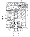
- a front housing member 11 is coupled to the front of a cylinder block 12.
- a rear housing member 13 is coupled to the rear of the cylinder block 12.
- the front housing member 11, the cylinder block 12, and the rear housing member 13 form a compressor housing.
- a crank chamber 14 is defined by the front housing member 11 and the cylinder block 12.
- the drive shaft 15 passes through the crank chamber 14 and is supported by the front housing member 11 and the cylinder block 12.
- a lug plate 16 is fixed to the drive shaft 15 in the crank chamber 14.
- a swash plate 17 is located in the crank chamber 14.
- a hinge mechanism 18 is located between the lug plate 16 and the swash plate 17. The lug plate 16 and the hinge mechanism 18 cause the swash plate 17 to rotate integrally with the drive shaft 15 and to incline relative to the axis L of the drive shaft 15. As shown by the broken line in Fig. 1, when the central part of the swash plate 17 slides toward the cylinder block 12, the inclination of the swash plate 17 decreases. When the central part of the swash plate 17 slides toward the lug plate 16, the inclination of the swash plate 17 increases.
- cylinder bores 19 are equally spaced from the axis L and are arranged at equal intervals.
- Single head pistons 20 are accommodated in the cylinder bores 19.
- the pistons 20 are coupled to the periphery of the swash plate 17 through the shoes 21. Rotation of the drive shaft 15 is converted into reciprocation of the pistons 20 through the lug plate 16, the hinge mechanism 18, the swash plate 17, and the shoes 21.
- the lug plate 16, the swash plate 17, and the hinge mechanism 18 form piston-driving parts.
- a suction chamber 22 and a discharge chamber 23 are formed in the rear housing member 13.
- An external drive source such as a vehicle engine (not shown) rotates the drive shaft 15, which reciprocates the pistons 20.
- refrigerant gas in the suction chamber 22 is drawn to the corresponding cylinder bore 19 through a corresponding suction valve 24.
- refrigerant gas in the corresponding cylinder bore 19 is compressed to a predetermined pressure and is discharged to the discharge chamber 23 through a corresponding discharge valve 25.
- a pressurizing passage 26 connects the discharge chamber 23 to the crank chamber 14.
- the control valve 27 opens and closes the pressurizing passage 26 by exciting and de-exciting a solenoid 27a in accordance with external signals, which are determined by the cooling load and the On/Off state of an air-conditioning switch (not shown).
- the control valve 27 adjusts the opening size of the pressurizing passage 26 and the flow rate of high pressure refrigerant gas to the crank chamber 14, which varies the pressure in the crank chamber 14. Accordingly, the difference between the pressure in the crank chamber 14 and that in the cylinder bores 19 is varied, which varies the inclination of the swash plate 17 and controls the displacement.
- a thrust bearing 30, which is a roller bearing, includes a front (left in Fig. 1) annular race 31, a rear annular race 32, and rolling elements, or rollers 33, which are radially arranged about the axis L between the races 31, 32.
- a front annular seat 34 is concentric with the drive shaft 15 and is formed on an inner wall 11a of the front housing member 11.
- a rear annular seat 35 is concentric with the drive shaft 15 and is formed on the front-end surface of the lug plate 16.
- the front race 31 is seated on the front annular seat 34, and the rear race 32 is seated on the rear annular seat 35. Accordingly, the thrust bearing 30 is held by the front and rear annular seats 34, 35 and is located between the front housing member 11 and the lug plate 16.
- the front annular seat 34 includes a flat pressure-receiving surface 34a.
- the rear annular seat 35 includes a flat pressure-receiving surface 35a.
- the diameter of the front annular seat 34 is different from that of the rear annular seat 35.
- the front annular seat 34 is located radially outward of the rear annular seat 35. Accordingly, the pressure-receiving surface 34a of the front seat 34 contacts a peripheral front surface of the front race 31, and the pressure-receiving surface 35a of the rear seat 35 contacts an inner rear surface of the rear race 32.
- the rollers 33 in the thrust bearing 30 roll on the front and rear races 31, 32 about the axis L.
- the inner diameter R1 of the contact area between the pressure-receiving surface 34a and the front race 31 is substantially equal to the outer diameter R2 of the path of the rollers 33.
- the outer diameter R3 of the contact area between the pressure-receiving surface 35a and the rear race 32 is substantially equal to the inner diameter R4 of the path of the rollers 33.
- the thrust bearing 110 is rigidly held between the housing 101 and the lug plate 104.
- the inclination of the piston-driving parts 104-106 causes a part of the lug plate 16 to contact the thrust bearing 110 in the manner of a fulcrum.
- An opposite part of the lug plate 16 is separated from the housing 101 by a significant distance.
- a part of the lug plate 16 opposite to a part of the lug plate 16 pressing the thrust bearing 30 acts as a fulcrum. Accordingly, the change of the distance from the opposite part to the front housing member 11 is small, that is, the thrust bearing 30, which is held between the opposite part and the front housing member 11, is stable.
- the illustrated embodiment has the following advantages.
- FIGs. 5 and 6 show a second embodiment.
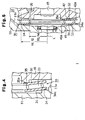
- a front annular limit portion 41 is located on the inner wall 11a of the front housing 11 radially inward of the front annular seat 34.
- a rear annular limit portion 42 is located on the front-end surface of the lug plate 16 radially outward of the rear annular seat 35.
- the front and rear limit portions 41, 42 respectively have limit surfaces 41a, 42a, which face the corresponding surfaces of the races 31, 32.
- the limit surface 41a of the front limit portion 41 is connected to the pressure-receiving surface 34a of the front annular seat 34 and has a tapered surface that increases in distance from the thrust bearing 30 toward the axis L of the drive shaft 15.
- the limit surface 42a of the rear limit portion 42 is connected to the pressure-receiving surface 35a of the rear annular seat 35 and has a tapered surface that increases in distance from the thrust bearing 30 in a radially outward direction.
- the present embodiment has the following advantages in addition to those of the first embodiment.
- the present invention can further be embodied as follows.
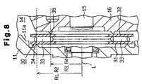
- the front annular seat 34 may be located radially inward of the rear annular seat 35.
- the outer diameter R5 of the contact area between the pressure-receiving surface 34a and the front race 31 is substantially equal to the inner diameter R6 of the path of the rollers 33.
- the inner diameter R7 of the contact area between the pressure-receiving surface 35a and the rear race 32 is substantially equal to the outer diameter R8 of the path of the rollers 33.
- the front and rear annular seats 34, 35 may be acute projections.
- the present embodiment has the same advantages as the first embodiment.
- balls may be used instead of the rollers 33 in the thrust bearing 30.
- the present invention may be applied to fixed displacement compressors.
- the present invention may also be applied to wobble piston-type compressors.
- a housing includes a crank chamber and cylinder bores. Pistons are accommodated in the cylinder bores.
- a drive shaft is supported by the housing to pass through the crank chamber.
- a lug plate is fixed to the drive shaft. The pistons are coupled to the lug plate, which converts rotation of the drive shaft into reciprocation of the pistons and compresses gas in the cylinder bores.
- a thrust bearing is located between the housing and the lug plate and transmits a thrust load applied to the lug plate.
- the thrust bearing includes a front race located next to the housing, a rear race located next to the lug plate, and rollers located between the front and rear races.
- a front seat for supporting the front race is formed on the housing.
- a rear seat for supporting the rear race is formed on the lug plate. The diameters of the front and rear seats are different, which causes elastic deformation of the races when a thrust load is applied.
Landscapes
- Engineering & Computer Science (AREA)
- General Engineering & Computer Science (AREA)
- Mechanical Engineering (AREA)
- Compressors, Vaccum Pumps And Other Relevant Systems (AREA)
Applications Claiming Priority (2)
| Application Number | Priority Date | Filing Date | Title |
|---|---|---|---|
| JP11112227A JP2000303951A (ja) | 1999-04-20 | 1999-04-20 | ピストン式圧縮機 |
| JP11222799 | 1999-04-20 |
Publications (2)
| Publication Number | Publication Date |
|---|---|
| EP1046817A2 true EP1046817A2 (fr) | 2000-10-25 |
| EP1046817A3 EP1046817A3 (fr) | 2001-03-21 |
Family
ID=14581444
Family Applications (1)
| Application Number | Title | Priority Date | Filing Date |
|---|---|---|---|
| EP00108546A Withdrawn EP1046817A3 (fr) | 1999-04-20 | 2000-04-19 | Butée de palier pour un compresseur à plateau en biais |
Country Status (3)
| Country | Link |
|---|---|
| US (1) | US6338613B1 (fr) |
| EP (1) | EP1046817A3 (fr) |
| JP (1) | JP2000303951A (fr) |
Cited By (4)
| Publication number | Priority date | Publication date | Assignee | Title |
|---|---|---|---|---|
| EP1281866A3 (fr) * | 2001-07-31 | 2004-03-24 | Kabushiki Kaisha Toyota Jidoshokki | Mécanisme d'amortissement des vibrations pour compresseur |
| EP1270942A3 (fr) * | 2001-06-30 | 2004-06-30 | Halla Climate Control Corporation | Palier de poussée pour le plateau en biais d'un compresseur |
| US6979182B2 (en) | 2001-07-31 | 2005-12-27 | Kabushiki Kaisha Toyota Jidoshokki | Vibration damping mechanism for piston type compressor |
| CN117345770A (zh) * | 2023-12-05 | 2024-01-05 | 中国航发四川燃气涡轮研究院 | 一种压气机试验器进气舱室系统 |
Families Citing this family (5)
| Publication number | Priority date | Publication date | Assignee | Title |
|---|---|---|---|---|
| JP2004124876A (ja) * | 2002-10-04 | 2004-04-22 | Toyota Industries Corp | 容量可変型斜板式圧縮機 |
| JP4654136B2 (ja) * | 2006-02-16 | 2011-03-16 | サンデン株式会社 | 往復動型流体機械 |
| EP2325489B1 (fr) * | 2008-10-27 | 2016-11-30 | Panasonic Corporation | Compresseur hermétique |
| DE102010033122B4 (de) * | 2010-08-03 | 2015-03-26 | Schaeffler Technologies Gmbh & Co. Kg | Axialwälzlager, insbesondere Axialnadellager |
| KR101426586B1 (ko) * | 2011-12-26 | 2014-08-05 | 한라비스테온공조 주식회사 | 압축기 |
Citations (3)
| Publication number | Priority date | Publication date | Assignee | Title |
|---|---|---|---|---|
| US3652188A (en) | 1970-06-01 | 1972-03-28 | Maruyama Mfg Co | High pressure pump |
| US3809508A (en) | 1971-12-06 | 1974-05-07 | Maruyama Mfg Co | Pump |
| US3920356A (en) | 1973-04-02 | 1975-11-18 | Cat Pumps Corp | Reciprocating pump |
Family Cites Families (10)
| Publication number | Priority date | Publication date | Assignee | Title |
|---|---|---|---|---|
| US3393022A (en) * | 1965-06-25 | 1968-07-16 | Rollway Bearing Company Inc | Cantilever thrust bearing |
| US4428718A (en) * | 1982-02-25 | 1984-01-31 | General Motors Corporation | Variable displacement compressor control valve arrangement |
| JP2946717B2 (ja) * | 1990-10-08 | 1999-09-06 | 株式会社豊田自動織機製作所 | 揺動斜板型圧縮機の軸受装置 |
| US5094590A (en) * | 1990-10-09 | 1992-03-10 | General Motors Corporation | Variable displacement compressor with shaft end play compensation |
| US5233913A (en) | 1992-08-31 | 1993-08-10 | General Motors Corporation | Swash plate compressor with spring thrust bearing assembly |
| JP3094720B2 (ja) * | 1993-02-15 | 2000-10-03 | 株式会社豊田自動織機製作所 | 斜板式圧縮機 |
| JP3417047B2 (ja) | 1994-05-02 | 2003-06-16 | 株式会社豊田自動織機 | 両頭斜板式圧縮機 |
| JPH08189464A (ja) * | 1994-11-11 | 1996-07-23 | Toyota Autom Loom Works Ltd | 可変容量型圧縮機 |
| KR100215157B1 (ko) * | 1996-06-19 | 1999-08-16 | 이소가이 지세이 | 가변용량 압축기 및 그 부착방법 |
| JP3787903B2 (ja) | 1996-08-05 | 2006-06-21 | 株式会社豊田自動織機 | 可変容量型圧縮機 |
-
1999
- 1999-04-20 JP JP11112227A patent/JP2000303951A/ja active Pending
-
2000
- 2000-04-19 EP EP00108546A patent/EP1046817A3/fr not_active Withdrawn
- 2000-04-19 US US09/552,274 patent/US6338613B1/en not_active Expired - Fee Related
Patent Citations (3)
| Publication number | Priority date | Publication date | Assignee | Title |
|---|---|---|---|---|
| US3652188A (en) | 1970-06-01 | 1972-03-28 | Maruyama Mfg Co | High pressure pump |
| US3809508A (en) | 1971-12-06 | 1974-05-07 | Maruyama Mfg Co | Pump |
| US3920356A (en) | 1973-04-02 | 1975-11-18 | Cat Pumps Corp | Reciprocating pump |
Cited By (7)
| Publication number | Priority date | Publication date | Assignee | Title |
|---|---|---|---|---|
| EP1270942A3 (fr) * | 2001-06-30 | 2004-06-30 | Halla Climate Control Corporation | Palier de poussée pour le plateau en biais d'un compresseur |
| EP1281866A3 (fr) * | 2001-07-31 | 2004-03-24 | Kabushiki Kaisha Toyota Jidoshokki | Mécanisme d'amortissement des vibrations pour compresseur |
| US6932582B2 (en) | 2001-07-31 | 2005-08-23 | Kabushiki Kaisha Toyota Jidoshokki | Vibration damping mechanism for piston type compressor |
| US6969241B2 (en) | 2001-07-31 | 2005-11-29 | Kabushiki Kaisha Toyota Jidoshokki | Vibration damping mechanism for piston type compressor |
| US6979182B2 (en) | 2001-07-31 | 2005-12-27 | Kabushiki Kaisha Toyota Jidoshokki | Vibration damping mechanism for piston type compressor |
| CN117345770A (zh) * | 2023-12-05 | 2024-01-05 | 中国航发四川燃气涡轮研究院 | 一种压气机试验器进气舱室系统 |
| CN117345770B (zh) * | 2023-12-05 | 2024-02-20 | 中国航发四川燃气涡轮研究院 | 一种压气机试验器进气舱室系统 |
Also Published As
| Publication number | Publication date |
|---|---|
| US6338613B1 (en) | 2002-01-15 |
| JP2000303951A (ja) | 2000-10-31 |
| EP1046817A3 (fr) | 2001-03-21 |
Similar Documents
| Publication | Publication Date | Title |
|---|---|---|
| AU670526B2 (en) | Variable displacement piston type compressor | |
| JPH0637874B2 (ja) | 可変容量圧縮機 | |
| US6338613B1 (en) | Piston-type compressor | |
| US6629823B2 (en) | Compressors | |
| US6203284B1 (en) | Valve arrangement at the discharge chamber of a variable displacement compressor | |
| US4730987A (en) | Variable delivery compressor | |
| US5704769A (en) | Noise suppressing mechanism in piston-type compressor | |
| US6293182B1 (en) | Piston-type compressor with piston guide | |
| EP1004769B1 (fr) | Compresseur à plateau en biais à capacité variable | |
| US6446540B1 (en) | Bearing for swash plate compressor | |
| US5737997A (en) | Cam plate supporting structure in a cam plate type compressor | |
| US6260469B1 (en) | Piston for use in a compressor | |
| US20030059316A1 (en) | Multistage type piston compressor | |
| EP0823552A2 (fr) | Mécanisme de guidage pour un piston de compresseur | |
| US6336392B1 (en) | Compressor which can be easily and efficiently assembled by facilitating adjustment of an axial clearance of a shaft | |
| EP1067288A2 (fr) | Palier de poussée pour le plateau oscillant d'un compresseur | |
| EP1207300B1 (fr) | Compresseur à plateau en biais | |
| US20070101859A1 (en) | Compressor | |
| US5231915A (en) | Wobble plate type compressor having cantilevered drive mechanism | |
| CN110836173A (zh) | 一种新型斜盘式汽车空调压缩机 | |
| US7168359B2 (en) | Swash plate compressor | |
| US6912948B2 (en) | Swash plate compressor | |
| EP1065375A2 (fr) | Régulation de pression dans la chambre de bielle d'un compresseur à plateau en biais | |
| EP1406013B1 (fr) | Compresseur à capacité variable | |
| US20060222513A1 (en) | Swash plate type variable displacement compressor |
Legal Events
| Date | Code | Title | Description |
|---|---|---|---|
| PUAI | Public reference made under article 153(3) epc to a published international application that has entered the european phase |
Free format text: ORIGINAL CODE: 0009012 |
|
| 17P | Request for examination filed |
Effective date: 20000419 |
|
| AK | Designated contracting states |
Kind code of ref document: A2 Designated state(s): DE FR IT |
|
| AX | Request for extension of the european patent |
Free format text: AL;LT;LV;MK;RO;SI |
|
| PUAL | Search report despatched |
Free format text: ORIGINAL CODE: 0009013 |
|
| AK | Designated contracting states |
Kind code of ref document: A3 Designated state(s): AT BE CH CY DE DK ES FI FR GB GR IE IT LI LU MC NL PT SE |
|
| AX | Request for extension of the european patent |
Free format text: AL;LT;LV;MK;RO;SI |
|
| AKX | Designation fees paid |
Free format text: DE FR IT |
|
| RAP1 | Party data changed (applicant data changed or rights of an application transferred) |
Owner name: KABUSHIKI KAISHA TOYOTA JIDOSHOKKI |
|
| 17Q | First examination report despatched |
Effective date: 20041124 |
|
| STAA | Information on the status of an ep patent application or granted ep patent |
Free format text: STATUS: THE APPLICATION IS DEEMED TO BE WITHDRAWN |
|
| 18D | Application deemed to be withdrawn |
Effective date: 20050405 |