EP1046868A2 - Kälteanlage mit einem ein optimiertes Verbrauch bietenden Kältekreislauf - Google Patents
Kälteanlage mit einem ein optimiertes Verbrauch bietenden Kältekreislauf Download PDFInfo
- Publication number
- EP1046868A2 EP1046868A2 EP20000107058 EP00107058A EP1046868A2 EP 1046868 A2 EP1046868 A2 EP 1046868A2 EP 20000107058 EP20000107058 EP 20000107058 EP 00107058 A EP00107058 A EP 00107058A EP 1046868 A2 EP1046868 A2 EP 1046868A2
- Authority
- EP
- European Patent Office
- Prior art keywords
- auxiliary
- main
- compressor
- condenser
- pressure
- Prior art date
- Legal status (The legal status is an assumption and is not a legal conclusion. Google has not performed a legal analysis and makes no representation as to the accuracy of the status listed.)
- Granted
Links
Images


Classifications
-
- F—MECHANICAL ENGINEERING; LIGHTING; HEATING; WEAPONS; BLASTING
- F25—REFRIGERATION OR COOLING; COMBINED HEATING AND REFRIGERATION SYSTEMS; HEAT PUMP SYSTEMS; MANUFACTURE OR STORAGE OF ICE; LIQUEFACTION SOLIDIFICATION OF GASES
- F25B—REFRIGERATION MACHINES, PLANTS OR SYSTEMS; COMBINED HEATING AND REFRIGERATION SYSTEMS; HEAT PUMP SYSTEMS
- F25B41/00—Fluid-circulation arrangements
-
- F—MECHANICAL ENGINEERING; LIGHTING; HEATING; WEAPONS; BLASTING
- F25—REFRIGERATION OR COOLING; COMBINED HEATING AND REFRIGERATION SYSTEMS; HEAT PUMP SYSTEMS; MANUFACTURE OR STORAGE OF ICE; LIQUEFACTION SOLIDIFICATION OF GASES
- F25B—REFRIGERATION MACHINES, PLANTS OR SYSTEMS; COMBINED HEATING AND REFRIGERATION SYSTEMS; HEAT PUMP SYSTEMS
- F25B49/00—Arrangement or mounting of control or safety devices
- F25B49/02—Arrangement or mounting of control or safety devices for compression type machines, plants or systems
- F25B49/022—Compressor control arrangements
-
- F—MECHANICAL ENGINEERING; LIGHTING; HEATING; WEAPONS; BLASTING
- F25—REFRIGERATION OR COOLING; COMBINED HEATING AND REFRIGERATION SYSTEMS; HEAT PUMP SYSTEMS; MANUFACTURE OR STORAGE OF ICE; LIQUEFACTION SOLIDIFICATION OF GASES
- F25B—REFRIGERATION MACHINES, PLANTS OR SYSTEMS; COMBINED HEATING AND REFRIGERATION SYSTEMS; HEAT PUMP SYSTEMS
- F25B2400/00—Component parts or details not otherwise provided for in this subclass
- F25B2400/03—Suction accumulators with deflectors
-
- F—MECHANICAL ENGINEERING; LIGHTING; HEATING; WEAPONS; BLASTING
- F25—REFRIGERATION OR COOLING; COMBINED HEATING AND REFRIGERATION SYSTEMS; HEAT PUMP SYSTEMS; MANUFACTURE OR STORAGE OF ICE; LIQUEFACTION SOLIDIFICATION OF GASES
- F25B—REFRIGERATION MACHINES, PLANTS OR SYSTEMS; COMBINED HEATING AND REFRIGERATION SYSTEMS; HEAT PUMP SYSTEMS
- F25B2400/00—Component parts or details not otherwise provided for in this subclass
- F25B2400/07—Details of compressors or related parts
- F25B2400/075—Details of compressors or related parts with parallel compressors
-
- F—MECHANICAL ENGINEERING; LIGHTING; HEATING; WEAPONS; BLASTING
- F25—REFRIGERATION OR COOLING; COMBINED HEATING AND REFRIGERATION SYSTEMS; HEAT PUMP SYSTEMS; MANUFACTURE OR STORAGE OF ICE; LIQUEFACTION SOLIDIFICATION OF GASES
- F25B—REFRIGERATION MACHINES, PLANTS OR SYSTEMS; COMBINED HEATING AND REFRIGERATION SYSTEMS; HEAT PUMP SYSTEMS
- F25B2400/00—Component parts or details not otherwise provided for in this subclass
- F25B2400/16—Receivers
- F25B2400/161—Receivers arranged in parallel
-
- F—MECHANICAL ENGINEERING; LIGHTING; HEATING; WEAPONS; BLASTING
- F25—REFRIGERATION OR COOLING; COMBINED HEATING AND REFRIGERATION SYSTEMS; HEAT PUMP SYSTEMS; MANUFACTURE OR STORAGE OF ICE; LIQUEFACTION SOLIDIFICATION OF GASES
- F25B—REFRIGERATION MACHINES, PLANTS OR SYSTEMS; COMBINED HEATING AND REFRIGERATION SYSTEMS; HEAT PUMP SYSTEMS
- F25B2500/00—Problems to be solved
- F25B2500/05—Cost reduction
-
- F—MECHANICAL ENGINEERING; LIGHTING; HEATING; WEAPONS; BLASTING
- F25—REFRIGERATION OR COOLING; COMBINED HEATING AND REFRIGERATION SYSTEMS; HEAT PUMP SYSTEMS; MANUFACTURE OR STORAGE OF ICE; LIQUEFACTION SOLIDIFICATION OF GASES
- F25B—REFRIGERATION MACHINES, PLANTS OR SYSTEMS; COMBINED HEATING AND REFRIGERATION SYSTEMS; HEAT PUMP SYSTEMS
- F25B2600/00—Control issues
- F25B2600/02—Compressor control
- F25B2600/021—Inverters therefor
-
- F—MECHANICAL ENGINEERING; LIGHTING; HEATING; WEAPONS; BLASTING
- F25—REFRIGERATION OR COOLING; COMBINED HEATING AND REFRIGERATION SYSTEMS; HEAT PUMP SYSTEMS; MANUFACTURE OR STORAGE OF ICE; LIQUEFACTION SOLIDIFICATION OF GASES
- F25B—REFRIGERATION MACHINES, PLANTS OR SYSTEMS; COMBINED HEATING AND REFRIGERATION SYSTEMS; HEAT PUMP SYSTEMS
- F25B5/00—Compression machines, plants or systems, with several evaporator circuits, e.g. for varying refrigerating capacity
- F25B5/02—Compression machines, plants or systems, with several evaporator circuits, e.g. for varying refrigerating capacity arranged in parallel
-
- Y—GENERAL TAGGING OF NEW TECHNOLOGICAL DEVELOPMENTS; GENERAL TAGGING OF CROSS-SECTIONAL TECHNOLOGIES SPANNING OVER SEVERAL SECTIONS OF THE IPC; TECHNICAL SUBJECTS COVERED BY FORMER USPC CROSS-REFERENCE ART COLLECTIONS [XRACs] AND DIGESTS
- Y02—TECHNOLOGIES OR APPLICATIONS FOR MITIGATION OR ADAPTATION AGAINST CLIMATE CHANGE
- Y02B—CLIMATE CHANGE MITIGATION TECHNOLOGIES RELATED TO BUILDINGS, e.g. HOUSING, HOUSE APPLIANCES OR RELATED END-USER APPLICATIONS
- Y02B30/00—Energy efficient heating, ventilation or air conditioning [HVAC]
- Y02B30/70—Efficient control or regulation technologies, e.g. for control of refrigerant flow, motor or heating
Definitions
- the present invention relates to a refrigeration system with a refrigeration cycle which provides optimized consumption.
- the invention relates to a refrigeration system which allows to save energy with respect to conventional refrigeration systems, which are adapted to refrigerate enclosed spaces or masses in general and to keep them at a lower temperature than the outside environment by using an external power source.
- vapor-compression type which operates by converting mechanical energy into heat energy by means of the single or multiple reverse thermodynamic cycle in which a refrigerant fluid evolves.
- the fluid is in the superheated saturated vapor phase.
- a certain fraction determined on the basis of the first and second laws of thermodynamics, is used at a temperature below the temperature outside the system in order to refrigerate enclosed spaces or masses.
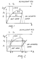
- Figure 1 is an enthalpy chart of the conventional type, in which enthalpy H per unit mass is plotted on the X-axis and the Y-axis plots the logarithm of pressure.
- Figure 1 plots two isothermal lines H1 and H2 on which state transitions occur at a different pressure and with different temperatures.
- wet vapor region The region between the upper and lower limiting curves is known as wet vapor region, since liquid and vapor are simultaneously present. It can also be noted that the enthalpies required to change state vary according to the pressure and tend to decrease (H2 is smaller than H1) as one approaches the critical pressure C, at which the state transition occurs without requiring heat.
- Figure 2 is an enthalpy chart which plots a conventional refrigeration cycle.
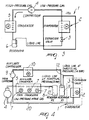
- the refrigeration system comprises a refrigeration cell inside which an evaporator 2 and an expansion valve 3 are arranged.
- the evaporator is connected to a compressor 4, which is in turn connected to a condenser 5 and to a reservoir 6 which is connected to the expansion valve 3.
- connection between the evaporator 2 and the compressor 4 is a connection in which gas at low pressure flows, while the connection between the compressor 4 and the condenser 5 is a connection in which high-pressure gas is present.
- a liquid line is provided between the reservoir 6 and the expansion valve 3.
- the point 1 of the chart corresponds to a step during which the refrigerant gas is at a pressure P1 in the dry saturated steam region; in this condition, it is aspirated by the compressor and compressed to the point 2, which corresponds to a pressure P2 > P1.
- the compression work applied to the gas by the compressor 4 is given by the difference in enthalpy H2-H1 and approximately corresponds to the energy expenditure of the refrigeration system.
- the temperature of the gas at the point 2 increases with respect to the temperature at the point 1: compression normally occurs in a very short time and it is therefore possible to consider this as an adiabatic transformation (i.e., involving no heat exchange).
- the high-pressure gas is then sent to the condenser 5, in which heat is removed.
- Desuperheating occurs in the first part of the condenser 5, and the refrigerant gas passes from the point 2 on the chart of Figure 3 to the point 3 of the same chart, and actual condensation begins, until all the gas is in the liquid state and is therefore subcooled until it reaches the point 4.
- the expansion valve 3, arranged upstream of the evaporator 2, is designed to create a pressure drop at constant enthalpy; i.e., the energy content of the refrigerant gas does not vary in this step.
- the cycle passes from point 4 to point 5, at which it is in the wet vapor region.
- the main variables to be defined are the evaporation pressure and the condensation pressure.
- the evaporation pressure is chosen according to the temperature of the refrigeration cell 1 to be cooled, in which the evaporator 2 is immersed, and according to the characteristics of the evaporator.
- the condensation pressure is instead usually determined by the maximum temperature that can be reached by the medium used to cool the condenser 3 (usually air), plus the temperature difference required by the condenser to operate.
- the condensation pressure corresponds to the temperature of 40°C.
- the temperature of the condensation air can drop considerably, accordingly entailing a decrease in the condensation pressure.
- the values of the condensation pressure may become so low as to prevent the correct operation of the expansion valve 3 and therefore the entire system stalls.
- the purpose of the expansion valve is to provide the isenthalpic expansion of the refrigerant fluid and requires a minimum pressure difference between the inlet and the outlet for its correct operation.
- This problem is normally solved by appropriately varying the ventilation on the condenser 5 so as to maintain a condensation pressure that corresponds to approximately 35°C.
- Ventilation is normally reduced by sequentially shutting down the fans 7, in the case of a multiple-fan condenser, or by reducing the rotation rate of said fans.
- the actual refrigeration cycle therefore, does not occur at the lowest possible condensation pressure (determined by the temperature of the condensation air), but is limited downwards so as to ensure circulation of the refrigerant gas.
- the aim of the present invention is to provide a refrigeration system in which energy consumption is optimized with respect to conventional systems.
- an object of the present invention is to provide a refrigeration system which allows gas refrigeration to occur at the lowest possible pressure.
- Another object of the present invention is to provide a refrigeration system which allows the compressor of the system to operate at lower temperatures and pressures than normally provided in conventional systems, thus reducing the wear of said compressor.
- Another object of the present invention is to provide a refrigeration system whose overall refrigeration capacity is higher than that of conventional systems.
- Another object of the present invention is to provide a refrigeration system in which the main section of the system is subjected to lower operating temperatures than those of conventional systems.
- Another object of the present invention is to provide a refrigeration system in which the main compressors are quieter than the compressors of conventional systems.
- Another object of the present invention is to provide a refrigeration system which can be used as a high-efficiency conditioning system.
- Another object of the present invention is to provide a refrigeration system which can allow to provide high-efficiency heat pumps.
- Another object of the present invention is to provide a refrigeration system which is highly reliable, relatively easy to manufacture and at competitive costs.
- a refrigeration system having a refrigeration cycle which provides optimized consumption, comprising a main section, which comprises at least one main compressor, a main condenser, which is connected between said compressor and at least one expansion valve, and at least one evaporator, which is connected to said expansion valve, characterized in that it comprises an auxiliary section which comprises at least one auxiliary compressor which is connected to a low-pressure intake line of said main compressor, an optional auxiliary condenser which is connected to said auxiliary compressor, and a first auxiliary reservoir and a second auxiliary reservoir which are respectively connected to the output of said optional auxiliary condenser and to the output of said main condenser, for connection to said at least one expansion valve.
- the refrigeration system comprises, like the system shown in Figure 3, a refrigeration cell 1 which internally accommodates an evaporator 2 and an expansion valve 3.
- Figure 4 uses the same reference numerals as Figure 3 to designate corresponding elements.
- At least one main compressor 4 is connected to the evaporator 2 by means of a duct in which intake gas, designated by the reference numeral 20, flows at low pressure.
- the compressor 4 is connected to a main condenser 5, which is provided with ventilation means 7 and is in turn connected to a reservoir 8.
- the refrigeration system according to the invention has a first section, which comprises the main compressor 4, the main condenser 5 and the reservoir 8, and is capable of condensing the gas drawn from the intake line 20 and compressed by the main compressor 4 at the lowest possible temperature allowed by the main condenser 5 (and by its cooling medium).
- the refrigerant fluid in output (at low pressure) accumulates in the reservoir 8, which is initially empty.
- connection between the main condenser 5 and the reservoir 8 is provided by means of a liquid line 21 at the condensation pressure (for example approximately 8 bar).
- the system according to the invention has a second or auxiliary section which is composed of an auxiliary compressor 9, an optional auxiliary condenser 10 and a second or auxiliary reservoir 11.
- auxiliary compressor 9 In order to allow to regulate the throttling pressure it is possible to vary the flow rate of the auxiliary compressor 9 using an inverter or any other adapted device. Instead of using the auxiliary condenser 10, it is possible to use a choke on the intake line toward the auxiliary compressor 9, with the aim of adjusting the throttling pressure, which can also be controlled with other conventional methods.
- the second section instead operates at the throttling pressure, and the second reservoir 11 is connected to the expansion valve 3 by means of a liquid line 12 at the throttling pressure (for example approximately 14 bar).
- the throttling pressure which is kept constant, ensures a delivery pressure of the circuit which is sufficient to feed the expansion valve 3.
- the gas compressed by the auxiliary compressor 9 in fact reaches the reservoir 11 (which is initially full) and pushes the liquid contained therein toward the expansion valve 3 at the throttling pressure.
- the refrigerant liquid that arrives from the main section is at low temperature and pressure, and when functional reservoir swapping occurs it is subjected to the throttling pressure and is therefore greatly subcooled.
- the auxiliary compressor is connected to the low-pressure line 20.
- the main section of the refrigeration system shown in Figure 4 comprises a plurality of main compressors 4 and a plurality of cells 1 which are arranged in parallel to each other.
- FIG 6 is a detailed view of the actual circuit of the refrigeration system according to the invention, illustrated only by way of schematic example in Figure 4.
- Figure 6 illustrates, in particular, a first step of the operation of the refrigeration system according to the invention
- Figures 7 and 8 illustrate further steps of its operation.
- the first reservoir 8 is part of the main section, while the second reservoir 11 is part of the auxiliary section of the refrigeration system according to the invention.
- the first and second reservoirs mutually swap their functions.
- the first or auxiliary reservoir 8 is connected to the auxiliary condenser by means of a valve VS1 and is connected to the output of the main condenser 5 by means of a non-return valve NRV1 and is then connected to the expansion valves 3 by means of a high-pressure line 14 and an additional non-return valve NRV3.
- the second reservoir 11 is connected to the auxiliary condenser 10 by means of a valve VS2 and is then connected to the output of the main condenser 5 by interposing a non-return valve NRV2 and is connected, by means of an additional non-return valve NRV4, to the low-pressure line 14 that leads to the connection to the expansion valves 3.
- each reservoir 8 and 11 is connected to the low-pressure line 20 by means of respective valves VS4 and VS3 and a bypass choke 18.
- the refrigeration system has a main section which comprises one or more main compressors 4, a main condenser 5 and one or more refrigeration cells, the output of the main condenser being connected to the expansion valves of the respective refrigeration cells 1; there is also an auxiliary section, which comprises one or more auxiliary compressors 9, an optional auxiliary condenser 10, and a first auxiliary reservoir 8 and a second auxiliary reservoir 11 which are respectively interposed between the output of the main condenser 5 and the throttling valves 3 of the respective refrigeration cells 1.
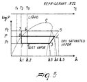
- Figure 5 schematically plots, on the enthalpy chart, the refrigeration cycles that are present in the refrigeration system according to the invention.
- the primary refrigeration cycle instead has a compression energy expenditure equal to H4-H3, with a refrigeration output which is equal to H3-H1 and with a refrigeration efficiency which is much higher than the preceding one, i.e., the following relation applies: (H3-H1)/(H4-H3) much greater than (H3-H2)/(H5-H3).
- the auxiliary compressor 10 draws the refrigerant gas from the intake line and feeds it at high pressure to the auxiliary condenser 10, in which a partial condensation occurs which is regulated (in the case of an air-cooled condenser) by the actuation and deactivation of the fan of the auxiliary condenser 10 (or by a variation in its speed), so as to keep the pressure at values which allow correct throttling in the thermostatic valves.
- the electric valve VS1 is open, while the electric valve VS2 is close, and therefore the gas reaches the auxiliary reservoir 8, where it pressurizes the liquid contained therein; the high-pressure liquid, by flowing along the line LR1, the non-return valve NRD2 and the line 14, reaches the main reservoir 25 (if provided), which rapidly fills.
- the line 14 connects the auxiliary reservoirs 8 and 11 directly to the expansion valves 3.
- the main compressor or compressors 10 in this step operate normally, and the gas drawn from the low-pressure intake line 20 is sent to the main condenser 5, where condensation occurs at the lowest possible pressure.
- the low-pressure refrigerant liquid by flowing along the line in output from the main condenser 5, the non-return valve NRV2 and the line LR2, reaches the auxiliary reservoir 11 and fills it.
- the filling of the reservoir 11 is facilitated by the fact that since the valve VS3 is open (while VS4 is closed), a small amount of the gas, by passing through the bypass choke 18, reaches the intake line, thus contributing to reduce pressure in the auxiliary reservoir 11 thus facilitating filling with the liquid that arrives from the main condenser 5.
- the auxiliary reservoir 11 fills with the liquid at low pressure and low temperature that arrives from the main condenser 5, and simultaneously the main reservoir 25 is emptied of the liquid maintained at high pressure by the auxiliary compressor 9.
- a transfer step then occurs again and the cycle is repeated.
- main compressors 4 constantly have the lowest discharge pressure allowed by the condensation exchanger, and that the auxiliary compressor 9 constantly keeps the liquid air supply pressure at values which are adequate for correct operation of the throttling valves.
- the refrigeration system according to the invention therefore allows the main section of the system to operate in optimum conditions, allowing in theory condensation at any temperature, the only limitation being due to the operating characteristics of the compressor.
- the auxiliary circuit instead ensures the correct supply pressure on the expansion valves in every operating condition and helps to generate cold, with considerable energy savings.
- the intense subcooling of the liquid eliminates the possibility of the so-called flash gas effect in the delivery piping.
- the materials used may be any according to requirements and the state of the art.
Landscapes
- Engineering & Computer Science (AREA)
- Physics & Mathematics (AREA)
- Mechanical Engineering (AREA)
- Thermal Sciences (AREA)
- General Engineering & Computer Science (AREA)
- Compression-Type Refrigeration Machines With Reversible Cycles (AREA)
- Devices That Are Associated With Refrigeration Equipment (AREA)
- Air Conditioning Control Device (AREA)
Applications Claiming Priority (2)
| Application Number | Priority Date | Filing Date | Title |
|---|---|---|---|
| IT1999TV000044A IT1311828B1 (it) | 1999-04-19 | 1999-04-19 | Impianto frigorifero avente ciclo frigorifero a consumo ottimizzato |
| ITTV990044 | 1999-04-19 |
Publications (3)
| Publication Number | Publication Date |
|---|---|
| EP1046868A2 true EP1046868A2 (de) | 2000-10-25 |
| EP1046868A3 EP1046868A3 (de) | 2001-10-24 |
| EP1046868B1 EP1046868B1 (de) | 2005-08-31 |
Family
ID=11420609
Family Applications (1)
| Application Number | Title | Priority Date | Filing Date |
|---|---|---|---|
| EP00107058A Expired - Lifetime EP1046868B1 (de) | 1999-04-19 | 2000-04-04 | Kälteanlage mit einem einen optimierten Verbrauch bietenden Kältekreislauf |
Country Status (8)
| Country | Link |
|---|---|
| US (1) | US6427460B1 (de) |
| EP (1) | EP1046868B1 (de) |
| JP (1) | JP2000304364A (de) |
| AT (1) | ATE303565T1 (de) |
| CA (1) | CA2303669C (de) |
| DE (1) | DE60022251T2 (de) |
| ES (1) | ES2247971T3 (de) |
| IT (1) | IT1311828B1 (de) |
Cited By (3)
| Publication number | Priority date | Publication date | Assignee | Title |
|---|---|---|---|---|
| EP1536192A1 (de) * | 2003-11-28 | 2005-06-01 | Birton A/S | Kälteanlage |
| WO2006044281A2 (en) | 2004-10-18 | 2006-04-27 | Carrier Corporation | Refrigerant cycle with tandem compressors and multiple condensers |
| EP1816415A2 (de) | 2006-02-07 | 2007-08-08 | Birton A/S | Kälteanlage mit Umlauf von flüssigem Kältemittel durch Druck |
Families Citing this family (15)
| Publication number | Priority date | Publication date | Assignee | Title |
|---|---|---|---|---|
| WO2004053401A1 (en) * | 2002-12-09 | 2004-06-24 | Danfoss (New Zealand) Limited | Liquid heating system |
| US6862894B1 (en) | 2004-02-04 | 2005-03-08 | Donald R. Miles | Adaptive auxiliary condensing device and method |
| WO2006015629A1 (en) * | 2004-08-09 | 2006-02-16 | Carrier Corporation | Flashgas removal from a receiver in a refrigeration circuit |
| US20060090505A1 (en) * | 2004-10-28 | 2006-05-04 | Carrier Corporation | Refrigerant cycle with tandem compressors for multi-level cooling |
| WO2006099378A1 (en) * | 2005-03-14 | 2006-09-21 | York International Corporation | Hvac system with powered subcooler |
| EP2087298A4 (de) * | 2006-11-30 | 2012-04-04 | Carrier Corp | Kältemittelladungslagerung |
| EP2283284B1 (de) * | 2008-06-12 | 2018-09-12 | Carrier Corporation | Kältezyklus und betriebsverfahren dafür |
| FR2932553B1 (fr) * | 2008-06-12 | 2013-08-16 | Jean Luc Maire | Systeme reversible de recuperation d'energie calorifique par prelevement et transfert de calories d'un ou plusieurs milieux dans un autre ou plusieurs autres milieux quelconques. |
| WO2010120519A2 (en) * | 2009-03-31 | 2010-10-21 | Johnson Controls Technology Company | Control system for operating condenser fans |
| US10378800B2 (en) * | 2011-09-23 | 2019-08-13 | Lennox Industries Inc. | Multi-staged water manifold system for a water source heat pump |
| CA2790732C (en) | 2011-09-26 | 2020-03-10 | Lennox Industries Inc. | Multi-staged water manifold system for a water source heat pump |
| CN103727705A (zh) * | 2012-10-15 | 2014-04-16 | 深圳市新迪能源科技有限公司 | 双源热泵纳米流体热能技术系统 |
| WO2017144666A1 (en) * | 2016-02-25 | 2017-08-31 | Abb Schweiz Ag | Heat exchanger assembly and method for operating a heat exchanger assembly |
| CN109506381A (zh) * | 2018-10-21 | 2019-03-22 | 武汉富诺尔节能环保科技有限公司 | 一种复叠式节能型制冷系统 |
| CN109682126B (zh) * | 2019-01-28 | 2024-08-09 | 天津商业大学 | 一种可降低制冷剂充注量的制冷系统 |
Family Cites Families (12)
| Publication number | Priority date | Publication date | Assignee | Title |
|---|---|---|---|---|
| US3122003A (en) * | 1962-03-13 | 1964-02-25 | American Radiator & Standard | Sequence changer |
| US3984224A (en) * | 1973-12-10 | 1976-10-05 | Dawkins Claude W | Air conditioning system for a motor home vehicle or the like |
| US3885938A (en) * | 1974-01-18 | 1975-05-27 | Westinghouse Electric Corp | Refrigeration system with capacity control |
| US4317334A (en) * | 1980-06-16 | 1982-03-02 | Silva Restaurant Equipment Co., Inc. | Remote refrigeration system with controlled air flow |
| US4324106A (en) * | 1980-10-03 | 1982-04-13 | H. A. Phillips & Co. | Refrigeration system |
| JPS6218933Y2 (de) * | 1981-04-14 | 1987-05-15 | ||
| US4418548A (en) | 1982-03-29 | 1983-12-06 | Trane Cac, Inc. | Variable capacity multiple compressor refrigeration system |
| JPS61134545A (ja) | 1984-12-01 | 1986-06-21 | 株式会社東芝 | 冷凍サイクル装置 |
| JPH0784110B2 (ja) | 1987-11-30 | 1995-09-13 | 凸版印刷株式会社 | 製本丁合機 |
| JPH02238270A (ja) * | 1989-03-09 | 1990-09-20 | Fuji Electric Co Ltd | 冷凍機のコンデンシングユニット |
| JPH037854A (ja) * | 1989-06-02 | 1991-01-16 | Mitsubishi Electric Corp | 冷凍装置 |
| JP2684814B2 (ja) | 1990-04-11 | 1997-12-03 | ダイキン工業株式会社 | 空気調和装置 |
-
1999
- 1999-04-19 IT IT1999TV000044A patent/IT1311828B1/it active
-
2000
- 2000-03-29 US US09/537,665 patent/US6427460B1/en not_active Expired - Fee Related
- 2000-04-03 JP JP2000100647A patent/JP2000304364A/ja active Pending
- 2000-04-03 CA CA002303669A patent/CA2303669C/en not_active Expired - Fee Related
- 2000-04-04 AT AT00107058T patent/ATE303565T1/de not_active IP Right Cessation
- 2000-04-04 DE DE60022251T patent/DE60022251T2/de not_active Expired - Fee Related
- 2000-04-04 EP EP00107058A patent/EP1046868B1/de not_active Expired - Lifetime
- 2000-04-04 ES ES00107058T patent/ES2247971T3/es not_active Expired - Lifetime
Cited By (4)
| Publication number | Priority date | Publication date | Assignee | Title |
|---|---|---|---|---|
| EP1536192A1 (de) * | 2003-11-28 | 2005-06-01 | Birton A/S | Kälteanlage |
| WO2006044281A2 (en) | 2004-10-18 | 2006-04-27 | Carrier Corporation | Refrigerant cycle with tandem compressors and multiple condensers |
| EP1802923A4 (de) * | 2004-10-18 | 2010-01-06 | Carrier Corp | Kühlmittelkreislauf mit tandemkompressoren und mehreren kondensatoren |
| EP1816415A2 (de) | 2006-02-07 | 2007-08-08 | Birton A/S | Kälteanlage mit Umlauf von flüssigem Kältemittel durch Druck |
Also Published As
| Publication number | Publication date |
|---|---|
| DE60022251T2 (de) | 2006-03-09 |
| ITTV990044A1 (it) | 2000-10-19 |
| ITTV990044A0 (it) | 1999-04-19 |
| JP2000304364A (ja) | 2000-11-02 |
| CA2303669C (en) | 2008-08-12 |
| ES2247971T3 (es) | 2006-03-16 |
| ATE303565T1 (de) | 2005-09-15 |
| DE60022251D1 (de) | 2005-10-06 |
| IT1311828B1 (it) | 2002-03-19 |
| EP1046868A3 (de) | 2001-10-24 |
| EP1046868B1 (de) | 2005-08-31 |
| CA2303669A1 (en) | 2000-10-19 |
| US6427460B1 (en) | 2002-08-06 |
Similar Documents
| Publication | Publication Date | Title |
|---|---|---|
| CA2303669C (en) | Refrigeration system having a refrigeration cycle which provides optimized consumption | |
| US10921030B2 (en) | Thermal energy system and method of operation | |
| US20250109896A1 (en) | Air conditioning system with capacity control and controlled hot water generation | |
| CA1040445A (en) | Heat pump with high efficiency reversible helical screw rotary compressor | |
| KR101155496B1 (ko) | 히트펌프식 급탕장치 | |
| US6817198B2 (en) | Method and apparatus for variable frequency controlled compressor and fan | |
| CN101900455B (zh) | 制冷装置 | |
| US7210303B2 (en) | Transcritical heat pump water heating system using auxiliary electric heater | |
| US20110016897A1 (en) | Air conditioning-hot water supply combined system | |
| KR100776371B1 (ko) | 에너지절감형 고효율 냉동시스템 및 그 제어방법 | |
| KR20060024438A (ko) | 냉각 시스템의 제어 | |
| CN102365510A (zh) | 空调热水供给复合系统 | |
| KR20150000449A (ko) | 급수 가온 시스템 | |
| JP2010127531A (ja) | 冷凍空調装置 | |
| CN102419024A (zh) | 制冷循环装置和热水采暖装置 | |
| CN100443824C (zh) | 制冷剂系统中的回油控制 | |
| CN100507398C (zh) | 冷冻装置 | |
| US3065610A (en) | Charge stabilizer for heat pump | |
| US20090223232A1 (en) | Defrost system | |
| KR200274119Y1 (ko) | 히트 펌프 시스템 | |
| JP5903577B2 (ja) | 冷凍装置 | |
| KR200426762Y1 (ko) | 에너지절감형 고효율 냉동시스템 | |
| AU2020360865B2 (en) | A heat pump | |
| JP2005326131A (ja) | 液冷媒加圧装置 | |
| CN114508874A (zh) | 压缩机冷却系统、冷却方法及空调 |
Legal Events
| Date | Code | Title | Description |
|---|---|---|---|
| PUAI | Public reference made under article 153(3) epc to a published international application that has entered the european phase |
Free format text: ORIGINAL CODE: 0009012 |
|
| AK | Designated contracting states |
Kind code of ref document: A2 Designated state(s): AT BE CH CY DE DK ES FI FR GB GR IE IT LI LU MC NL PT SE |
|
| AX | Request for extension of the european patent |
Free format text: AL;LT;LV;MK;RO;SI |
|
| PUAL | Search report despatched |
Free format text: ORIGINAL CODE: 0009013 |
|
| AK | Designated contracting states |
Kind code of ref document: A3 Designated state(s): AT BE CH CY DE DK ES FI FR GB GR IE IT LI LU MC NL PT SE |
|
| AX | Request for extension of the european patent |
Free format text: AL;LT;LV;MK;RO;SI |
|
| RIC1 | Information provided on ipc code assigned before grant |
Free format text: 7F 25B 1/00 A, 7F 25B 49/02 B, 7F 25B 41/00 B |
|
| 17P | Request for examination filed |
Effective date: 20020322 |
|
| AKX | Designation fees paid |
Free format text: AT BE CH CY DE DK ES FI FR GB GR IE IT LI LU MC NL PT SE |
|
| AXX | Extension fees paid |
Free format text: LT PAYMENT 20020322;LV PAYMENT 20020322;RO PAYMENT 20020322;SI PAYMENT 20020322 |
|
| 17Q | First examination report despatched |
Effective date: 20031124 |
|
| GRAP | Despatch of communication of intention to grant a patent |
Free format text: ORIGINAL CODE: EPIDOSNIGR1 |
|
| GRAS | Grant fee paid |
Free format text: ORIGINAL CODE: EPIDOSNIGR3 |
|
| GRAA | (expected) grant |
Free format text: ORIGINAL CODE: 0009210 |
|
| AK | Designated contracting states |
Kind code of ref document: B1 Designated state(s): AT BE CH CY DE DK ES FI FR GB GR IE IT LI LU MC NL PT SE |
|
| AX | Request for extension of the european patent |
Extension state: LT LV RO SI |
|
| PG25 | Lapsed in a contracting state [announced via postgrant information from national office to epo] |
Ref country code: LI Free format text: LAPSE BECAUSE OF FAILURE TO SUBMIT A TRANSLATION OF THE DESCRIPTION OR TO PAY THE FEE WITHIN THE PRESCRIBED TIME-LIMIT Effective date: 20050831 Ref country code: CH Free format text: LAPSE BECAUSE OF FAILURE TO SUBMIT A TRANSLATION OF THE DESCRIPTION OR TO PAY THE FEE WITHIN THE PRESCRIBED TIME-LIMIT Effective date: 20050831 Ref country code: FI Free format text: LAPSE BECAUSE OF FAILURE TO SUBMIT A TRANSLATION OF THE DESCRIPTION OR TO PAY THE FEE WITHIN THE PRESCRIBED TIME-LIMIT Effective date: 20050831 Ref country code: NL Free format text: LAPSE BECAUSE OF FAILURE TO SUBMIT A TRANSLATION OF THE DESCRIPTION OR TO PAY THE FEE WITHIN THE PRESCRIBED TIME-LIMIT Effective date: 20050831 |
|
| REG | Reference to a national code |
Ref country code: CH Ref legal event code: EP Ref country code: GB Ref legal event code: FG4D |
|
| REG | Reference to a national code |
Ref country code: IE Ref legal event code: FG4D |
|
| REF | Corresponds to: |
Ref document number: 60022251 Country of ref document: DE Date of ref document: 20051006 Kind code of ref document: P |
|
| PG25 | Lapsed in a contracting state [announced via postgrant information from national office to epo] |
Ref country code: SE Free format text: LAPSE BECAUSE OF FAILURE TO SUBMIT A TRANSLATION OF THE DESCRIPTION OR TO PAY THE FEE WITHIN THE PRESCRIBED TIME-LIMIT Effective date: 20051130 Ref country code: GR Free format text: LAPSE BECAUSE OF FAILURE TO SUBMIT A TRANSLATION OF THE DESCRIPTION OR TO PAY THE FEE WITHIN THE PRESCRIBED TIME-LIMIT Effective date: 20051130 Ref country code: DK Free format text: LAPSE BECAUSE OF FAILURE TO SUBMIT A TRANSLATION OF THE DESCRIPTION OR TO PAY THE FEE WITHIN THE PRESCRIBED TIME-LIMIT Effective date: 20051130 |
|
| PG25 | Lapsed in a contracting state [announced via postgrant information from national office to epo] |
Ref country code: PT Free format text: LAPSE BECAUSE OF FAILURE TO SUBMIT A TRANSLATION OF THE DESCRIPTION OR TO PAY THE FEE WITHIN THE PRESCRIBED TIME-LIMIT Effective date: 20060222 |
|
| LTIE | Lt: invalidation of european patent or patent extension |
Effective date: 20050831 |
|
| NLV1 | Nl: lapsed or annulled due to failure to fulfill the requirements of art. 29p and 29m of the patents act | ||
| REG | Reference to a national code |
Ref country code: CH Ref legal event code: PL |
|
| REG | Reference to a national code |
Ref country code: ES Ref legal event code: FG2A Ref document number: 2247971 Country of ref document: ES Kind code of ref document: T3 |
|
| PG25 | Lapsed in a contracting state [announced via postgrant information from national office to epo] |
Ref country code: IE Free format text: LAPSE BECAUSE OF NON-PAYMENT OF DUE FEES Effective date: 20060404 |
|
| PG25 | Lapsed in a contracting state [announced via postgrant information from national office to epo] |
Ref country code: MC Free format text: LAPSE BECAUSE OF NON-PAYMENT OF DUE FEES Effective date: 20060430 |
|
| ET | Fr: translation filed | ||
| PLBE | No opposition filed within time limit |
Free format text: ORIGINAL CODE: 0009261 |
|
| STAA | Information on the status of an ep patent application or granted ep patent |
Free format text: STATUS: NO OPPOSITION FILED WITHIN TIME LIMIT |
|
| 26N | No opposition filed |
Effective date: 20060601 |
|
| REG | Reference to a national code |
Ref country code: IE Ref legal event code: MM4A |
|
| PG25 | Lapsed in a contracting state [announced via postgrant information from national office to epo] |
Ref country code: LU Free format text: LAPSE BECAUSE OF NON-PAYMENT OF DUE FEES Effective date: 20060404 |
|
| PGFP | Annual fee paid to national office [announced via postgrant information from national office to epo] |
Ref country code: AT Payment date: 20080429 Year of fee payment: 9 |
|
| PG25 | Lapsed in a contracting state [announced via postgrant information from national office to epo] |
Ref country code: CY Free format text: LAPSE BECAUSE OF FAILURE TO SUBMIT A TRANSLATION OF THE DESCRIPTION OR TO PAY THE FEE WITHIN THE PRESCRIBED TIME-LIMIT Effective date: 20050831 |
|
| PGFP | Annual fee paid to national office [announced via postgrant information from national office to epo] |
Ref country code: GB Payment date: 20080418 Year of fee payment: 9 |
|
| GBPC | Gb: european patent ceased through non-payment of renewal fee |
Effective date: 20090404 |
|
| PG25 | Lapsed in a contracting state [announced via postgrant information from national office to epo] |
Ref country code: AT Free format text: LAPSE BECAUSE OF NON-PAYMENT OF DUE FEES Effective date: 20090404 |
|
| PGFP | Annual fee paid to national office [announced via postgrant information from national office to epo] |
Ref country code: DE Payment date: 20091022 Year of fee payment: 10 Ref country code: ES Payment date: 20091006 Year of fee payment: 10 |
|
| PGFP | Annual fee paid to national office [announced via postgrant information from national office to epo] |
Ref country code: BE Payment date: 20090929 Year of fee payment: 10 |
|
| PG25 | Lapsed in a contracting state [announced via postgrant information from national office to epo] |
Ref country code: GB Free format text: LAPSE BECAUSE OF NON-PAYMENT OF DUE FEES Effective date: 20090404 |
|
| PGFP | Annual fee paid to national office [announced via postgrant information from national office to epo] |
Ref country code: FR Payment date: 20091019 Year of fee payment: 10 Ref country code: IT Payment date: 20090928 Year of fee payment: 10 |
|
| BERE | Be: lapsed |
Owner name: *ZANON LUCIANO Effective date: 20100430 |
|
| REG | Reference to a national code |
Ref country code: FR Ref legal event code: ST Effective date: 20101230 |
|
| PG25 | Lapsed in a contracting state [announced via postgrant information from national office to epo] |
Ref country code: DE Free format text: LAPSE BECAUSE OF NON-PAYMENT OF DUE FEES Effective date: 20101103 |
|
| PG25 | Lapsed in a contracting state [announced via postgrant information from national office to epo] |
Ref country code: IT Free format text: LAPSE BECAUSE OF NON-PAYMENT OF DUE FEES Effective date: 20100404 Ref country code: BE Free format text: LAPSE BECAUSE OF NON-PAYMENT OF DUE FEES Effective date: 20100430 |
|
| REG | Reference to a national code |
Ref country code: ES Ref legal event code: FD2A Effective date: 20110714 |
|
| PG25 | Lapsed in a contracting state [announced via postgrant information from national office to epo] |
Ref country code: ES Free format text: LAPSE BECAUSE OF NON-PAYMENT OF DUE FEES Effective date: 20110704 |
|
| PG25 | Lapsed in a contracting state [announced via postgrant information from national office to epo] |
Ref country code: ES Free format text: LAPSE BECAUSE OF NON-PAYMENT OF DUE FEES Effective date: 20100405 |
|
| PG25 | Lapsed in a contracting state [announced via postgrant information from national office to epo] |
Ref country code: FR Free format text: LAPSE BECAUSE OF NON-PAYMENT OF DUE FEES Effective date: 20100430 |