EP1046869A1 - Système de réfrigération et d'air conditionné - Google Patents
Système de réfrigération et d'air conditionné Download PDFInfo
- Publication number
- EP1046869A1 EP1046869A1 EP20000303315 EP00303315A EP1046869A1 EP 1046869 A1 EP1046869 A1 EP 1046869A1 EP 20000303315 EP20000303315 EP 20000303315 EP 00303315 A EP00303315 A EP 00303315A EP 1046869 A1 EP1046869 A1 EP 1046869A1
- Authority
- EP
- European Patent Office
- Prior art keywords
- gas
- pressure
- liquid
- liquid mixture
- expander
- Prior art date
- Legal status (The legal status is an assumption and is not a legal conclusion. Google has not performed a legal analysis and makes no representation as to the accuracy of the status listed.)
- Granted
Links
Images


Classifications
-
- F—MECHANICAL ENGINEERING; LIGHTING; HEATING; WEAPONS; BLASTING
- F25—REFRIGERATION OR COOLING; COMBINED HEATING AND REFRIGERATION SYSTEMS; HEAT PUMP SYSTEMS; MANUFACTURE OR STORAGE OF ICE; LIQUEFACTION SOLIDIFICATION OF GASES
- F25B—REFRIGERATION MACHINES, PLANTS OR SYSTEMS; COMBINED HEATING AND REFRIGERATION SYSTEMS; HEAT PUMP SYSTEMS
- F25B9/00—Compression machines, plants or systems, in which the refrigerant is air or other gas of low boiling point
- F25B9/002—Compression machines, plants or systems, in which the refrigerant is air or other gas of low boiling point characterised by the refrigerant
- F25B9/008—Compression machines, plants or systems, in which the refrigerant is air or other gas of low boiling point characterised by the refrigerant the refrigerant being carbon dioxide
-
- F—MECHANICAL ENGINEERING; LIGHTING; HEATING; WEAPONS; BLASTING
- F25—REFRIGERATION OR COOLING; COMBINED HEATING AND REFRIGERATION SYSTEMS; HEAT PUMP SYSTEMS; MANUFACTURE OR STORAGE OF ICE; LIQUEFACTION SOLIDIFICATION OF GASES
- F25B—REFRIGERATION MACHINES, PLANTS OR SYSTEMS; COMBINED HEATING AND REFRIGERATION SYSTEMS; HEAT PUMP SYSTEMS
- F25B1/00—Compression machines, plants or systems with non-reversible cycle
- F25B1/10—Compression machines, plants or systems with non-reversible cycle with multi-stage compression
-
- F—MECHANICAL ENGINEERING; LIGHTING; HEATING; WEAPONS; BLASTING
- F25—REFRIGERATION OR COOLING; COMBINED HEATING AND REFRIGERATION SYSTEMS; HEAT PUMP SYSTEMS; MANUFACTURE OR STORAGE OF ICE; LIQUEFACTION SOLIDIFICATION OF GASES
- F25B—REFRIGERATION MACHINES, PLANTS OR SYSTEMS; COMBINED HEATING AND REFRIGERATION SYSTEMS; HEAT PUMP SYSTEMS
- F25B11/00—Compression machines, plants or systems, using turbines, e.g. gas turbines
- F25B11/02—Compression machines, plants or systems, using turbines, e.g. gas turbines as expanders
-
- F—MECHANICAL ENGINEERING; LIGHTING; HEATING; WEAPONS; BLASTING
- F25—REFRIGERATION OR COOLING; COMBINED HEATING AND REFRIGERATION SYSTEMS; HEAT PUMP SYSTEMS; MANUFACTURE OR STORAGE OF ICE; LIQUEFACTION SOLIDIFICATION OF GASES
- F25B—REFRIGERATION MACHINES, PLANTS OR SYSTEMS; COMBINED HEATING AND REFRIGERATION SYSTEMS; HEAT PUMP SYSTEMS
- F25B2309/00—Gas cycle refrigeration machines
- F25B2309/06—Compression machines, plants or systems characterised by the refrigerant being carbon dioxide
- F25B2309/061—Compression machines, plants or systems characterised by the refrigerant being carbon dioxide with cycle highest pressure above the supercritical pressure
-
- F—MECHANICAL ENGINEERING; LIGHTING; HEATING; WEAPONS; BLASTING
- F25—REFRIGERATION OR COOLING; COMBINED HEATING AND REFRIGERATION SYSTEMS; HEAT PUMP SYSTEMS; MANUFACTURE OR STORAGE OF ICE; LIQUEFACTION SOLIDIFICATION OF GASES
- F25B—REFRIGERATION MACHINES, PLANTS OR SYSTEMS; COMBINED HEATING AND REFRIGERATION SYSTEMS; HEAT PUMP SYSTEMS
- F25B2400/00—Component parts or details not otherwise provided for in this subclass
- F25B2400/13—Economisers
-
- F—MECHANICAL ENGINEERING; LIGHTING; HEATING; WEAPONS; BLASTING
- F25—REFRIGERATION OR COOLING; COMBINED HEATING AND REFRIGERATION SYSTEMS; HEAT PUMP SYSTEMS; MANUFACTURE OR STORAGE OF ICE; LIQUEFACTION SOLIDIFICATION OF GASES
- F25B—REFRIGERATION MACHINES, PLANTS OR SYSTEMS; COMBINED HEATING AND REFRIGERATION SYSTEMS; HEAT PUMP SYSTEMS
- F25B2400/00—Component parts or details not otherwise provided for in this subclass
- F25B2400/23—Separators
-
- F—MECHANICAL ENGINEERING; LIGHTING; HEATING; WEAPONS; BLASTING
- F25—REFRIGERATION OR COOLING; COMBINED HEATING AND REFRIGERATION SYSTEMS; HEAT PUMP SYSTEMS; MANUFACTURE OR STORAGE OF ICE; LIQUEFACTION SOLIDIFICATION OF GASES
- F25B—REFRIGERATION MACHINES, PLANTS OR SYSTEMS; COMBINED HEATING AND REFRIGERATION SYSTEMS; HEAT PUMP SYSTEMS
- F25B40/00—Subcoolers, desuperheaters or superheaters
Definitions
- the present invention relates to a two-phase mechanical refrigeration system and its use in refrigeration and/or air conditioning applications.
- HFCs Hydrofluorocarbons
- Natural refrigerants such as ammonia, are also used quite widely in industrial refrigeration.
- Another natural refrigerant is carbon dioxide. This was used extensively on ships in the early part of this century, but fell out of favour on the introduction of "Freons” or chlorofluorocarbons (CFCs) because of the extremely high pressures generated in the vapour compression cycle.
- CFCs chlorofluorocarbons
- gaseous carbon dioxide is first compressed to a pressure and temperature above its critical point.
- the high pressure gas is then cooled and passed through a throttling device which allows the refrigerant to form a gas/liquid mixture at constant enthalpy.
- the mixture is then finally evaporated back to a gas.
- Increased efficiency is achieved because the internal losses of the cycle are typically lower than that of a conventional vapour compression cycle.
- a two-phase mechanical refrigeration system comprises
- the principal difference between the present invention and a conventional two-phase mechanical refrigerant system is the inclusion of a secondary, or intermediate, compressor to pre-compress gas returning to the primary compressor. This has the effect of reducing the pressure differential across the primary compressor, rendering that compressor more efficient and reducing the work it needs to do to compress the gaseous refrigerant.
- the secondary compressor is itself driven by the work generated in the expander by expansion of the refrigerant material.
- consideration has been given as to whether use may be made of the work generated on expansion.
- One application where the work done on expansion has been used to positive effect is in the so-called "Boot Strap" air conditioning system utilised in aircraft.
- this system is a one phase gas compression system, which utilises the work done on expansion to drive an intermediate compressor rather than to pre-compress the gas for the primary compressor.
- the total cycle efficiency is increased, as judged by the coefficient of performance (COP), compared to conventional two-phase mechanical refrigeration cycles.
- COP coefficient of performance
- the two-phase mechanical refrigeration system described above is incorporated into a refrigeration or air conditioning apparatus or system, or a heat pump.
- a preferred application of the present invention is in vehicle air conditioning, for instance in automobiles, aircraft and ships, most preferably in automobiles.
- the refrigeration system of the present invention may also find use in buildings or on fixed sites, such as industrial plants, for any of the above applications.
- a process for providing refrigeration or air conditioning comprises the following steps:
- the two-phase mechanical refrigeration system of the present invention can be used, with appropriate modification, for a variety of refrigerant materials, above or below the critical point of the respective refrigerant material.
- refrigerant materials include carbon dioxide, ammonia, and chlorofluorocarbon and hydrofluorocarbon refrigerants.
- the system is operated using carbon dioxide as the refrigerant, more preferably under conditions of a trans-critical vapour compression cycle, as it is in this cycle that the most significant improvement in efficiency is observed.
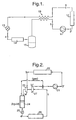
- gaseous carbon dioxide enters a compressor (11) where it is compressed to a pressure and temperature above its critical point.
- the gas is then cooled by cooler (12), throttled by way of expansion valve (13) to reduce its pressure, and then subject to evaporation in evaporator (14).
- the gas/liquid mixture exiting the evaporator enters liquid accumulator (15), and the gas separated is recycled to the primary compressor via heat exchanger (18) , which serves to cool gas en route from cooler (12) to expansion valve (13).
- gaseous carbon dioxide is compressed to a pressure and temperature above its critical point.
- the high pressure gas then enters the gas cooler (22), where its temperature is reduced while maintaining its pressure substantially constant. This can result in the formation of a gas/liquid mixture, depending on the conditions and the refrigerant employed. However, in the case of carbon dioxide generally a cooled high pressure gas will be formed.
- the basic functions of the two phase mechanical refrigeration system of the invention are essentially the same as the standard trans-critical system described in relation to Figure 1.
- substantially all the high pressure gas, or the gas/liquid mixture if appropriate, emerging from the gas cooler then enters an expander (23), where the gas is expanded to a lower, intermediate, pressure and temperature resulting in formation of a gas/liquid mixture at I e '.
- substantially all the gas, or gas/liquid mixture we mean all the gas or gas/liquid mixture other than small amounts, for instance up to 5 wt.%, of refrigerant material that may be lost, for instance, through internal leakage.
- the system of the invention does not include a device for separating off some of the refrigerant material prior to expansion through the expander.
- This mixture then enters a combined gas separator/liquid accumulator (24), which separates the gaseous portion of the mixture for recycling to point X, prior to the primary compressor, and directs the liquid portion of the mixture through an expansion, or throttle, valve (25), and to an evaporator (26).
- a combined gas separator/liquid accumulator 24
- This mixture then enters a combined gas separator/liquid accumulator (24), which separates the gaseous portion of the mixture for recycling to point X, prior to the primary compressor, and directs the liquid portion of the mixture through an expansion, or throttle, valve (25), and to an evaporator (26).
- a liquid accumulator can be positioned after the evaporator, as in the conventional trans-critical cycle shown in Figure 1.
- a simple expansion or throttling valve with no feedback mechanism can be used, although the positioning of liquid accumulator after the evaporator is critical, to prevent liquid entering, and therefore damaging, the compressors used in the cycle.
- Preferably means are provided to separate the gaseous refrigerant from the gas/liquid mixture prior to its entry into the expansion valve. The gas separated in this manner is then recycled to the primary compressor.
- Evaporation and cooling take place in the evaporator (26) as in a conventional refrigeration system, resulting in a gas at relatively low temperature and pressure.
- the gas leaving the evaporator then enters a secondary, or intermediate, compressor (27) which is connected to the expander (23) and the power generated by the expander drives this compressor.
- a secondary power source for instance a motor
- the secondary compressor is directly connected by mechanical means, for instance by a shaft, to the expander.
- the secondary compressor acts to compress gas to a pressure intermediate that of the pressure of the gas exiting the evaporator and the pressure achieved by way of the primary compressor.
- this intermediate pressure would be equal to the pressure of the gas/liquid mixture obtained after expansion in the expander (23). In a real system, however, it is inevitable that some pressure losses will occur. Accordingly, in the context of the present invention, when we refer to this intermediate pressure being substantially equal to the pressure obtained after expansion, we take into account pressure losses typically incurred in operating a mechanical refrigeration cycle. In practice the amount of pressure loss can vary quite considerably, from as low as a few percent on the high pressure side of the cycle to up to 20%, or higher, on the low pressure side of the cycle.
- the expander/secondary compressor unit is self-regulating, in that a balance of pressure will be achieved once the expander power output is equal to the work done in driving the secondary compressor and overcoming the friction associated therewith. This is, therefore, a stable system, with negative feedback, rendering any external controls or regulation unnecessary.
- the gas exiting the secondary compressor under conditions I c ' then mixes with the gas from the liquid gas separator/liquid accumulator, at point X.
- the gas mixture then enters the primary compressor, and the vapour compression cycle is completed.
- the gas from the gas separator/liquid accumulator may be used to cool the gas from the gas cooler, by way of gas-to-gas heat exchanger.
- the gas from the gas separator/liquid accumulator may itself be used to cool a body, or to pre-cool outside air entering a vehicle, for instance by way of an air-to-gas heat exchanger.
- FIG 4 shows an additional, or alternative, position for a heat exchanger to be incorporated into the system shown in Figure 3, across points Y and Z.
- Liquid-to-gas heat exchanger (29) is positioned after the gas separator/accumulator and prior to the expansion valve. It functions by allowing the cold gas exiting the evaporator (26) to pre-cool the liquid flowing from the gas separator to the expansion or throttling valve (25). Again, this has the effect of increasing the overall performance and efficiency of the system.
- the types of components for use in the system of the present invention i.e. the compressors, gas cooler (or condenser), expanders and evaporators may be any of the components conventionally used in vapour compression system.
- the gas cooler is referred to as such because it acts simple to cool the gas, rather than condense a portion of that gas into liquid. Any conventional condenser can be used for this purpose.
- the expander and/or compressors comprise axial or radial turbines, for instance of the type used in engine turbochargers. Radial turbine expanders and compressors are particularly preferred.
- a further consequence of the use of the expander/secondary compressor unit is that the gas returned to the primary compressor, on completion of the refrigeration cycle, is higher and denser than for the standard trans-critical cycle.
- the primary compressor can be reduced in size inversely proportional to the increase in gas density observed, allowing a cost saving.
- the expander and/or compressors may be made of lightweight materials, such as aluminum and plastics reinforced with, for instance, glass or other mineral fibres. The combined benefit of reduced dimensions and reduced material and manufacturing costs makes the use of such turbines particularly attractive in the field of automobile air conditioning.
- a seal should be provided between the expander the secondary compressor, to reduce leakage of refrigerants.
- Any suitable seal may be utilised for this purpose, for instance a lip type dynamic seal.
- the system may include a control device, or feedback mechanism, for the expansion or throttling valve.
- a control device or feedback mechanism, for the expansion or throttling valve.
- the advantage of using a control device is two-fold. First, all the liquid is converted to gas in the evaporator, thereby maximising the available cooling effect. Second, no liquid can return to the compressor, and so the conventional hazards of pumping liquid are avoided.
- An example of an expansion valve which includes a control device of this type is controlled in this manner is a so-called thermostatic expansion valve (TXV).
- TXV thermostatic expansion valve
- the valve is responsive to a sensor positioned after the evaporator which measures the thermodynamic characteristics of the material leaving the evaporator.
- TXV thermostatic expansion valve
- one of the preferred applications of the present invention is in vehicle air conditioning, and in particular automobile air conditioning.
- the system according to the invention may be incorporated as an air conditioning system in the conventional way.
- the system of the invention will be used to provide a cooling effect and will be arranged in parallel with a heating system, behind the dashboard of an automobile.
- Means are provided, typically in the form of air flaps, to vary the amount of air, which enters the automobile from the outside, passing through the system of the present invention and through the heating system arranged in parallel therewith, in order to achieve the desired environment within the automobile.
- Figure 5 shows the pressure/enthalpy diagram for a carbon dioxide trans-critical cycle, marked up to correspond to points on the schematic shown in Figure 1.
- the conditions of pressure, temperature and enthalpy at each of the points in the cycle are listed in Table 1 below, as for an air conditioning system. For simplicity, the contribution made by the heat exchanger (18) is not included.
- Figure 6 shows the pressure/enthalpy diagram for a carbon dioxide trans-critical cycle, marked up to correspond to points on the schematic in Figure 2.
- the conditions of pressure, temperature and enthalpy at each of the points in the cycle are listed in Table 2 below, as for an air conditioning system.
- I vapour represents the gas exiting the gas separator (24), I c ' the gas exiting the intermediate compressor, and I liquid the liquid exiting the gas separator/liquid accumulator.
- the isentropic efficiency of the primary compressor in the systems of Figures 1 and 2 is assumed to be 0.75, which is typical for piston compressor.
- the isentropic efficiency of the secondary compressor in the cycle shown in Figure 2 is assumed to be 0.80, which is typical for a radial turbine compressor.
- the coefficient of performance (COP) for the system of Figure 2 can be calculated to be 2.35.
- the COP calculated for the conventional system shown in Figure 1 can be calculated to be 1.38.
- the system of the present invention is, therefore, considerably more efficient than the conventional system.
- the power produced by the expander is equal to the power absorbed by the compressor and can overcome the normal mechanical losses in operating such equipment.
Landscapes
- Engineering & Computer Science (AREA)
- Physics & Mathematics (AREA)
- Mechanical Engineering (AREA)
- Thermal Sciences (AREA)
- General Engineering & Computer Science (AREA)
- Chemical & Material Sciences (AREA)
- Chemical Kinetics & Catalysis (AREA)
- Air-Conditioning For Vehicles (AREA)
Priority Applications (1)
| Application Number | Priority Date | Filing Date | Title |
|---|---|---|---|
| EP20000303315 EP1046869B1 (fr) | 1999-04-20 | 2000-04-19 | Système de réfrigération et d'air conditionné |
Applications Claiming Priority (3)
| Application Number | Priority Date | Filing Date | Title |
|---|---|---|---|
| EP99303027 | 1999-04-20 | ||
| EP99303027 | 1999-04-20 | ||
| EP20000303315 EP1046869B1 (fr) | 1999-04-20 | 2000-04-19 | Système de réfrigération et d'air conditionné |
Publications (2)
| Publication Number | Publication Date |
|---|---|
| EP1046869A1 true EP1046869A1 (fr) | 2000-10-25 |
| EP1046869B1 EP1046869B1 (fr) | 2005-02-02 |
Family
ID=26073133
Family Applications (1)
| Application Number | Title | Priority Date | Filing Date |
|---|---|---|---|
| EP20000303315 Expired - Lifetime EP1046869B1 (fr) | 1999-04-20 | 2000-04-19 | Système de réfrigération et d'air conditionné |
Country Status (1)
| Country | Link |
|---|---|
| EP (1) | EP1046869B1 (fr) |
Cited By (17)
| Publication number | Priority date | Publication date | Assignee | Title |
|---|---|---|---|---|
| WO2003019085A1 (fr) * | 2001-08-31 | 2003-03-06 | Mærsk Container Industri A/S | Dispositif a cycle de compression de vapeur |
| EP1359379A1 (fr) | 2002-04-15 | 2003-11-05 | Sanden Corporation | Système frigorifique utilisant le dioxyde de carbone comme réfrigérant |
| EP1411308A3 (fr) * | 2002-10-18 | 2004-06-30 | Matsushita Electric Industrial Co., Ltd. | Appareil à cycle frigorifique |
| WO2004055451A1 (fr) * | 2002-12-16 | 2004-07-01 | Lg Electronics Inc. | Systeme de refrigeration et son compresseur |
| EP1467158A3 (fr) * | 2003-04-09 | 2004-12-01 | Hitachi, Ltd. | Appareil a cycle de réfrigération |
| WO2005019743A1 (fr) * | 2003-06-16 | 2005-03-03 | Carrier Corporation | Regulation de pression supercritique d'un systeme de compression de vapeur |
| WO2006015741A1 (fr) * | 2004-08-09 | 2006-02-16 | Linde Kältetechnik Gmbh | Circuit frigorifique et procede de fonctionnement d'un circuit frigorifique |
| JP2006242491A (ja) * | 2005-03-04 | 2006-09-14 | Mitsubishi Electric Corp | 冷凍サイクル装置 |
| EP1855068A3 (fr) * | 2006-05-10 | 2008-11-05 | Sanden Corporation | Cycle de réfrigération à compression de vapeur |
| CN100582603C (zh) * | 2004-08-09 | 2010-01-20 | 林德制冷技术有限责任公司 | 制冷循环回路和用于运行制冷循环回路的方法 |
| EP2097686A4 (fr) * | 2006-12-26 | 2010-03-10 | Carrier Corp | Système de réfrigération à base de co2 équipé de compresseurs en tandem, d'un détendeur et d'un économiseur |
| EP1596140A3 (fr) * | 2004-05-14 | 2010-04-28 | Robert Bosch Gmbh | Dispositif pour l'expansion d'un réfrigérant |
| JP2013092293A (ja) * | 2011-10-25 | 2013-05-16 | Daikin Industries Ltd | 冷凍装置 |
| JP2013092292A (ja) * | 2011-10-25 | 2013-05-16 | Daikin Industries Ltd | 冷凍装置 |
| CN103512256A (zh) * | 2013-09-22 | 2014-01-15 | 孙西峰 | 一种制冷系统及空调 |
| CN106705470A (zh) * | 2016-12-12 | 2017-05-24 | 珠海格力电器股份有限公司 | 一种满液式制冷机组 |
| WO2020194945A1 (fr) * | 2019-03-27 | 2020-10-01 | 三菱重工サーマルシステムズ株式会社 | Dispositif à cycle frigorifique |
Families Citing this family (1)
| Publication number | Priority date | Publication date | Assignee | Title |
|---|---|---|---|---|
| US11105539B2 (en) | 2017-12-01 | 2021-08-31 | Johnson Controls Technology Company | Heating, ventilation, and air conditioning system with primary and secondary heat transfer loops |
Citations (3)
| Publication number | Priority date | Publication date | Assignee | Title |
|---|---|---|---|---|
| US2494120A (en) * | 1947-09-23 | 1950-01-10 | Phillips Petroleum Co | Expansion refrigeration system and method |
| EP0030636A2 (fr) * | 1979-12-10 | 1981-06-24 | Hughes Aircraft Company | Système cryogénique à compresseur et détendeur à vis, muni d'un accouplement magnétique |
| US4896515A (en) * | 1986-03-25 | 1990-01-30 | Mitsui Engineering & Shipbuilding Co. | Heat pump, energy recovery method and method of curtailing power for driving compressor in the heat pump |
-
2000
- 2000-04-19 EP EP20000303315 patent/EP1046869B1/fr not_active Expired - Lifetime
Patent Citations (3)
| Publication number | Priority date | Publication date | Assignee | Title |
|---|---|---|---|---|
| US2494120A (en) * | 1947-09-23 | 1950-01-10 | Phillips Petroleum Co | Expansion refrigeration system and method |
| EP0030636A2 (fr) * | 1979-12-10 | 1981-06-24 | Hughes Aircraft Company | Système cryogénique à compresseur et détendeur à vis, muni d'un accouplement magnétique |
| US4896515A (en) * | 1986-03-25 | 1990-01-30 | Mitsui Engineering & Shipbuilding Co. | Heat pump, energy recovery method and method of curtailing power for driving compressor in the heat pump |
Cited By (25)
| Publication number | Priority date | Publication date | Assignee | Title |
|---|---|---|---|---|
| WO2003019085A1 (fr) * | 2001-08-31 | 2003-03-06 | Mærsk Container Industri A/S | Dispositif a cycle de compression de vapeur |
| EP1359379A1 (fr) | 2002-04-15 | 2003-11-05 | Sanden Corporation | Système frigorifique utilisant le dioxyde de carbone comme réfrigérant |
| EP1411308A3 (fr) * | 2002-10-18 | 2004-06-30 | Matsushita Electric Industrial Co., Ltd. | Appareil à cycle frigorifique |
| US6945066B2 (en) | 2002-10-18 | 2005-09-20 | Matsushita Electric Industrial Co., Ltd. | Refrigeration cycle apparatus |
| WO2004055451A1 (fr) * | 2002-12-16 | 2004-07-01 | Lg Electronics Inc. | Systeme de refrigeration et son compresseur |
| EP1467158A3 (fr) * | 2003-04-09 | 2004-12-01 | Hitachi, Ltd. | Appareil a cycle de réfrigération |
| US6923016B2 (en) | 2003-04-09 | 2005-08-02 | Sunao Funakoshi | Refrigeration cycle apparatus |
| WO2005019743A1 (fr) * | 2003-06-16 | 2005-03-03 | Carrier Corporation | Regulation de pression supercritique d'un systeme de compression de vapeur |
| US6898941B2 (en) | 2003-06-16 | 2005-05-31 | Carrier Corporation | Supercritical pressure regulation of vapor compression system by regulation of expansion machine flowrate |
| EP1596140A3 (fr) * | 2004-05-14 | 2010-04-28 | Robert Bosch Gmbh | Dispositif pour l'expansion d'un réfrigérant |
| CN100582603C (zh) * | 2004-08-09 | 2010-01-20 | 林德制冷技术有限责任公司 | 制冷循环回路和用于运行制冷循环回路的方法 |
| EP2264385A3 (fr) * | 2004-08-09 | 2011-10-19 | Linde Kältetechnik GmbH | Cycle frigorifique et procédé d'operation d'un cycle frigorifique |
| CN101713596B (zh) * | 2004-08-09 | 2012-08-08 | 林德制冷技术有限责任公司 | 制冷循环回路和用于运行制冷循环回路的方法 |
| EP2244040A3 (fr) * | 2004-08-09 | 2011-10-12 | Linde Kältetechnik GmbH | Vidange de vapeur instantanée du réservoir d'un circuit refrigérant |
| WO2006015741A1 (fr) * | 2004-08-09 | 2006-02-16 | Linde Kältetechnik Gmbh | Circuit frigorifique et procede de fonctionnement d'un circuit frigorifique |
| AU2005270472B2 (en) * | 2004-08-09 | 2011-01-06 | Carrier Corporation | Refrigeration circuit and method for operating a refrigeration circuit |
| JP2006242491A (ja) * | 2005-03-04 | 2006-09-14 | Mitsubishi Electric Corp | 冷凍サイクル装置 |
| EP1855068A3 (fr) * | 2006-05-10 | 2008-11-05 | Sanden Corporation | Cycle de réfrigération à compression de vapeur |
| EP2097686A4 (fr) * | 2006-12-26 | 2010-03-10 | Carrier Corp | Système de réfrigération à base de co2 équipé de compresseurs en tandem, d'un détendeur et d'un économiseur |
| JP2013092293A (ja) * | 2011-10-25 | 2013-05-16 | Daikin Industries Ltd | 冷凍装置 |
| JP2013092292A (ja) * | 2011-10-25 | 2013-05-16 | Daikin Industries Ltd | 冷凍装置 |
| CN103512256A (zh) * | 2013-09-22 | 2014-01-15 | 孙西峰 | 一种制冷系统及空调 |
| CN106705470A (zh) * | 2016-12-12 | 2017-05-24 | 珠海格力电器股份有限公司 | 一种满液式制冷机组 |
| CN106705470B (zh) * | 2016-12-12 | 2022-09-23 | 珠海格力电器股份有限公司 | 一种满液式制冷机组 |
| WO2020194945A1 (fr) * | 2019-03-27 | 2020-10-01 | 三菱重工サーマルシステムズ株式会社 | Dispositif à cycle frigorifique |
Also Published As
| Publication number | Publication date |
|---|---|
| EP1046869B1 (fr) | 2005-02-02 |
Similar Documents
| Publication | Publication Date | Title |
|---|---|---|
| EP1046869B1 (fr) | Système de réfrigération et d'air conditionné | |
| US6293108B1 (en) | Regenerative refrigeration system with mixed refrigerants | |
| Groll et al. | Review of recent advances toward transcritical CO2 cycle technology | |
| US6460371B2 (en) | Multistage compression refrigerating machine for supplying refrigerant from subcooler to cool rotating machine and lubricating oil | |
| US8726677B2 (en) | Waste heat air conditioning system | |
| US6425249B1 (en) | High efficiency refrigeration system | |
| US20060242985A1 (en) | Refrigeration/air-conditioning apparatus powered by an engine exhaust gas driven turbine | |
| US20120234026A1 (en) | High efficiency refrigeration system and cycle | |
| US20030177782A1 (en) | Method for increasing efficiency of a vapor compression system by evaporator heating | |
| US20100313582A1 (en) | High efficiency r744 refrigeration system and cycle | |
| US6430937B2 (en) | Vortex generator to recover performance loss of a refrigeration system | |
| US7367202B2 (en) | Refrigerant cycle device with ejector | |
| JP2001221517A (ja) | 超臨界冷凍サイクル | |
| KR102184161B1 (ko) | 팽창-압축 장치를 구비한 냉매 회로 및 상기 냉매 회로를 작동시키기 위한 방법 | |
| EP1509733B1 (fr) | Moteur de machine auxiliaire commande par l'intermediaire d'un detendeur | |
| EP1263619B1 (fr) | Dispositif de climatisation destine en particulier a des vehicules automobiles, et procede pour faire fonctionner ce dispositif | |
| JP4400522B2 (ja) | エジェクタ式冷凍サイクル | |
| WO2001067011A1 (fr) | Systeme frigorifique haute efficacite | |
| JPH0868567A (ja) | 低温生成装置 | |
| US6862897B2 (en) | Vapor-compression refrigerant cycle with ejector | |
| JP3942501B2 (ja) | 車両用空調装置 | |
| JP2002156163A (ja) | 空気調和装置 | |
| Sullivan | Principles of vapour compression heat pumps | |
| JP2010112690A (ja) | エジェクタ式冷凍サイクル | |
| JP2001012810A (ja) | 冷房装置 |
Legal Events
| Date | Code | Title | Description |
|---|---|---|---|
| PUAI | Public reference made under article 153(3) epc to a published international application that has entered the european phase |
Free format text: ORIGINAL CODE: 0009012 |
|
| AK | Designated contracting states |
Kind code of ref document: A1 Designated state(s): DE FR |
|
| AX | Request for extension of the european patent |
Free format text: AL;LT;LV;MK;RO;SI |
|
| 17P | Request for examination filed |
Effective date: 20010420 |
|
| AKX | Designation fees paid |
Free format text: DE FR |
|
| 17Q | First examination report despatched |
Effective date: 20030410 |
|
| GRAP | Despatch of communication of intention to grant a patent |
Free format text: ORIGINAL CODE: EPIDOSNIGR1 |
|
| GRAS | Grant fee paid |
Free format text: ORIGINAL CODE: EPIDOSNIGR3 |
|
| RIN1 | Information on inventor provided before grant (corrected) |
Inventor name: NORRIS, CONRAD WILLIAM HENRY |
|
| GRAA | (expected) grant |
Free format text: ORIGINAL CODE: 0009210 |
|
| AK | Designated contracting states |
Kind code of ref document: B1 Designated state(s): DE FR |
|
| REF | Corresponds to: |
Ref document number: 60017824 Country of ref document: DE Date of ref document: 20050310 Kind code of ref document: P |
|
| PLBE | No opposition filed within time limit |
Free format text: ORIGINAL CODE: 0009261 |
|
| STAA | Information on the status of an ep patent application or granted ep patent |
Free format text: STATUS: NO OPPOSITION FILED WITHIN TIME LIMIT |
|
| 26N | No opposition filed |
Effective date: 20051103 |
|
| ET | Fr: translation filed | ||
| REG | Reference to a national code |
Ref country code: DE Ref legal event code: R082 Ref document number: 60017824 Country of ref document: DE Representative=s name: MEISSNER, BOLTE & PARTNER GBR, DE Ref country code: DE Ref legal event code: R082 Ref document number: 60017824 Country of ref document: DE Representative=s name: MEISSNER BOLTE PATENTANWAELTE RECHTSANWAELTE P, DE |
|
| REG | Reference to a national code |
Ref country code: DE Ref legal event code: R082 Ref document number: 60017824 Country of ref document: DE Representative=s name: MEISSNER, BOLTE & PARTNER GBR, DE |
|
| REG | Reference to a national code |
Ref country code: FR Ref legal event code: PLFP Year of fee payment: 17 |
|
| REG | Reference to a national code |
Ref country code: DE Ref legal event code: R082 Ref document number: 60017824 Country of ref document: DE Representative=s name: MEISSNER, BOLTE & PARTNER GBR, DE Ref country code: DE Ref legal event code: R081 Ref document number: 60017824 Country of ref document: DE Owner name: SANDEN HOLDINGS CORPORATION, LSESAKI-SHI, JP Free format text: FORMER OWNER: SANDEN CORP., ISESAKI, GUNMA, JP Ref country code: DE Ref legal event code: R082 Ref document number: 60017824 Country of ref document: DE Representative=s name: MEISSNER BOLTE PATENTANWAELTE RECHTSANWAELTE P, DE |
|
| REG | Reference to a national code |
Ref country code: FR Ref legal event code: CD Owner name: SANDEN HOLDINGS CORPORATION, JP Effective date: 20160525 |
|
| REG | Reference to a national code |
Ref country code: FR Ref legal event code: PLFP Year of fee payment: 18 |
|
| REG | Reference to a national code |
Ref country code: FR Ref legal event code: PLFP Year of fee payment: 19 |
|
| PGFP | Annual fee paid to national office [announced via postgrant information from national office to epo] |
Ref country code: DE Payment date: 20190418 Year of fee payment: 20 |
|
| PGFP | Annual fee paid to national office [announced via postgrant information from national office to epo] |
Ref country code: FR Payment date: 20190424 Year of fee payment: 20 |
|
| REG | Reference to a national code |
Ref country code: DE Ref legal event code: R071 Ref document number: 60017824 Country of ref document: DE |