EP1046879B1 - Procédé pour le sautage de masses rocheuses - Google Patents
Procédé pour le sautage de masses rocheuses Download PDFInfo
- Publication number
- EP1046879B1 EP1046879B1 EP00107537A EP00107537A EP1046879B1 EP 1046879 B1 EP1046879 B1 EP 1046879B1 EP 00107537 A EP00107537 A EP 00107537A EP 00107537 A EP00107537 A EP 00107537A EP 1046879 B1 EP1046879 B1 EP 1046879B1
- Authority
- EP
- European Patent Office
- Prior art keywords
- blasting
- detonation
- borehole
- velocity
- rock
- Prior art date
- Legal status (The legal status is an assumption and is not a legal conclusion. Google has not performed a legal analysis and makes no representation as to the accuracy of the status listed.)
- Expired - Lifetime
Links
- 239000011435 rock Substances 0.000 title claims description 47
- 238000005422 blasting Methods 0.000 title claims description 44
- 238000000034 method Methods 0.000 title claims description 23
- 230000035939 shock Effects 0.000 claims description 54
- 239000002360 explosive Substances 0.000 claims description 35
- 238000005474 detonation Methods 0.000 claims description 24
- 238000004519 manufacturing process Methods 0.000 claims description 18
- 230000000694 effects Effects 0.000 claims description 11
- 230000001934 delay Effects 0.000 claims description 10
- 238000005259 measurement Methods 0.000 claims description 2
- 238000005094 computer simulation Methods 0.000 claims 1
- 230000004992 fission Effects 0.000 claims 1
- 230000001360 synchronised effect Effects 0.000 claims 1
- 230000009466 transformation Effects 0.000 claims 1
- 238000004880 explosion Methods 0.000 description 17
- 238000010304 firing Methods 0.000 description 9
- 238000007664 blowing Methods 0.000 description 5
- 239000000463 material Substances 0.000 description 5
- 239000003990 capacitor Substances 0.000 description 4
- 238000004146 energy storage Methods 0.000 description 4
- 230000005284 excitation Effects 0.000 description 4
- 239000007787 solid Substances 0.000 description 4
- 230000015572 biosynthetic process Effects 0.000 description 3
- 238000005553 drilling Methods 0.000 description 3
- 238000005755 formation reaction Methods 0.000 description 3
- 230000001960 triggered effect Effects 0.000 description 3
- 230000006835 compression Effects 0.000 description 2
- 238000007906 compression Methods 0.000 description 2
- 230000006378 damage Effects 0.000 description 2
- 238000004090 dissolution Methods 0.000 description 2
- 230000005489 elastic deformation Effects 0.000 description 2
- 238000013467 fragmentation Methods 0.000 description 2
- 238000006062 fragmentation reaction Methods 0.000 description 2
- 230000001902 propagating effect Effects 0.000 description 2
- 230000001850 reproductive effect Effects 0.000 description 2
- 238000004088 simulation Methods 0.000 description 2
- 238000009825 accumulation Methods 0.000 description 1
- 230000003321 amplification Effects 0.000 description 1
- 238000013459 approach Methods 0.000 description 1
- 230000008033 biological extinction Effects 0.000 description 1
- 238000002485 combustion reaction Methods 0.000 description 1
- 238000005056 compaction Methods 0.000 description 1
- 238000010924 continuous production Methods 0.000 description 1
- 230000008878 coupling Effects 0.000 description 1
- 238000010168 coupling process Methods 0.000 description 1
- 238000005859 coupling reaction Methods 0.000 description 1
- 230000001186 cumulative effect Effects 0.000 description 1
- 230000006735 deficit Effects 0.000 description 1
- 230000003111 delayed effect Effects 0.000 description 1
- 230000001419 dependent effect Effects 0.000 description 1
- 238000013461 design Methods 0.000 description 1
- 238000009826 distribution Methods 0.000 description 1
- 229910052500 inorganic mineral Inorganic materials 0.000 description 1
- 230000002452 interceptive effect Effects 0.000 description 1
- 238000011835 investigation Methods 0.000 description 1
- 239000011707 mineral Substances 0.000 description 1
- 238000003032 molecular docking Methods 0.000 description 1
- 238000003199 nucleic acid amplification method Methods 0.000 description 1
- 238000003892 spreading Methods 0.000 description 1
- 230000002889 sympathetic effect Effects 0.000 description 1
- 230000002123 temporal effect Effects 0.000 description 1
- 238000011144 upstream manufacturing Methods 0.000 description 1
Images

Classifications
-
- F—MECHANICAL ENGINEERING; LIGHTING; HEATING; WEAPONS; BLASTING
- F42—AMMUNITION; BLASTING
- F42D—BLASTING
- F42D1/00—Blasting methods or apparatus, e.g. loading or tamping
-
- G—PHYSICS
- G01—MEASURING; TESTING
- G01V—GEOPHYSICS; GRAVITATIONAL MEASUREMENTS; DETECTING MASSES OR OBJECTS; TAGS
- G01V1/00—Seismology; Seismic or acoustic prospecting or detecting
- G01V1/02—Generating seismic energy
- G01V1/104—Generating seismic energy using explosive charges
- G01V1/108—Generating seismic energy using explosive charges by deforming or displacing surfaces of enclosures
Definitions
- the invention relates to a method for blasting Rock masses or similar masses above ground or Underground, after which explosive charges in each borehole associated igniter are used, and then the igniter and their respective delay intervals to each other in Dependence on the mineralogical / geological environment and the resulting seismic speeds as well as taking into account the respective shot pattern be programmed.
- blasting procedures are without adjustment of the respective Delay intervals from practice or European Patent application 0 147 688 A2 and the German published application DE 197 21 839 A1 known.
- a pyrotechnic is regularly used Ignition charge in connection with a glow plug resorted to, which is heated by electrical energy becomes.
- a non-electrical detonator usually consists of a thin plastic tube in which an explosive is included. This hose will blow detonated or in turn by a detonator initiated. The plastic hose will also ignite you pyrotechnic delay set in the actual igniter.
- Electronic detonators come without a pyrotechnic one Ignition charge off. Because they get their energy regularly via an energy store, for example a capacitor. This capacitor is used to ignite a glow plug or another electrically heatable device, such as this is basically in the already mentioned European script or German published patent DE 197 21 839 A1 is described.
- the invention is based on the technical problem to further develop such a process that not only a targeted mutual influence of those of the individual shock holes outgoing shock waves but also the explosive effect in the borehole can be influenced.
- the invention proposes Generic method for blasting rock masses or similar masses before that each in a borehole an electronic ground igniter and an electronic one Head detonators are used and on the same or one deviating ignition timing can be programmed, and that therefore opposite detonation fronts in about Middle of the charge column while doubling the Detonation speed and accelerated implementation of the The charging station meet.
- the set ignition delays preferably correspond between the first and last borehole to one Ignition rate (horizontal ignition rate) which are equal to or greater than the speed of sound in the to be blasted rock (rock speed).
- the energy storage or Downstream capacitor electronic switch (usually in the form of a switching transistor) for the fact that in the conductive state of the energy storage on the an ignition cable connected to the ignition device is discharged.
- the electronic switch or switching transistor with the help of a data control part including a central one Control unit, i.e. a computer in the form of a Microchips, controlled accordingly.
- a data control part including a central one Control unit, i.e. a computer in the form of a Microchips, controlled accordingly.
- the invention proposes to increase the Explosive effect before that individual, from the respective Shock wave fronts emanating from holes to open the Structure of the rock to be blasted together interfere. So there is an interference of the Shock waves and consequently the generated seismic Waves. This clash of the different multiple wave fronts leads to the desired opening of the Structure, that is to say that the bonds in the respective solids due to external excitation solve (at least partially).
- shock waves become themselves spatially spreading abrupt but constant changes of density, pressure and / or temperature of each understood explosive material.
- a shock wave arises when suddenly a large amount of energy is released - namely by the described explosion or detonating the explosive charge in the associated borehole with the help of the (electronic) detonator.
- the front this energy spread represents a shock wave.
- Their propagation speed or the shock wave speed can be a multiple of the speed of sound of the associated medium and moves in the supersonic area.
- shock wave velocity mostly in Mach numbers are located in the supersonic area of 1 and greater for this speed.
- the set ignition delays correspond to a cumulative sum less than that from the Speed of sound resulting in the rock to be blasted Running time. That is, the horizontal ignition speed is equal to or greater than the speed of sound in the rock to be blasted.
- This near field area is characterized in that the shock wave or seismic generated by the explosion Wave is particularly high frequency here.
- This high frequency Shock wave approaches the speed of sound depending on the distance in the rock to be blasted and also the associated natural frequency.
- shock effect described can be reduced to one as it were impulse-like excitation of the rock masses as a result the detonation of the explosive charge in the associated borehole return which in the frequency domain to the here observed ultra high frequencies in the range of 400 Hz corresponds to several kHz.
- the frequency and amplitude of these shock waves suitable in the near field or close range (blasting area), to stimulate the solid structure of the rock masses so strongly that this is a partial or total dissolution of the Solid body results. Consequently, the near-field area or the immediate area the actual blasting area, within which there is the seismic wave or shock wave concentric from the center of the excitation source, i.e. the Explosive charge or the borehole.
- the ignition speed must match the physical speeds (especially speed of sound) be adjusted.
- the invention proposes that the seismic speed or speed of sound in the previously exploding rock, d. H. before programming the Detonator and, of course, before the explosion, metrologically and / or is determined mathematically by simulations.
- drilling logs can be used, for example use a fairly accurate replica of each Deliver rock formations. From these drilling logs can depend on the expected seismic speeds be inferred so that based on this Findings of the horizontal ignition speed, i.e. the Ignition speed from the first borehole to last borehole, dimensioned or adjusted.
- shock wave In addition to the generated seismic wave or sound wave (Shock wave) is also used to shred the blasted rock a time after implementation of the Explosives following gas pressure wave. This is with compared to the seismic wave slower propagation speed, the so-called detonation pressure wave velocity, generated. Again supports the Gas blast the explosive effect of the shock wave. Because this Gas pressure wave penetrates into existing hairline cracks, so that the associated chunks of rock are opened become. It is also conceivable that the gas pressure wave itself Crushed rock or certain chunks of rock.
- the invention further provides that the shock wave velocity or seismic velocity and the blast wave velocity coordinated and in supersonic resp Subsonic speed range are located.
- Pre-garbage blasting and production blasting not only distinguish from each other, but also synchronize. Under gap rows are within the scope of the invention certain well topologies in the context of the generated borehole pattern to understand. Find such pre-gap rows mostly as a limitation of the actual Blasting area and should u. a. for one as straight as possible and stable dismantling wall after the explosion has ended. Accordingly, it is conceivable that pre-gap boreholes Enclose the blasting area as a whole or at least on one Limit side where described straight and stable Dismantling wall is desired. Blowing up the associated Explosive charges in the holes forming the pre-gap rows is referred to as pre-garbage. in the In contrast, production explosions serve the real thing Purpose, the rock masses within the blasting field or to explode the explosive area.
- a synchronization between pre-gap blasting takes place and demolition of production in such a way that Vibrations in the blasting area (and also outside the Explosive area) are neutralized. Ideally it will ie the blasting area (and the surrounding area) or the desired dismantling wall only slightly shaken.
- the pre-splitting technique described enables especially in sensitive and even inhabited areas previously defined and defined limitation of the blasting area.
- the pre-gap row practically forms one Reflection horizon for the actual production explosion.
- the subject of the invention is also a Borehole patterns as set out in claims 9 and 10 is described.
- the regularly used electronic allow Detonator practically total control over each programmed ignition timing. This cannot be done only master the rate of combustion of the explosives, but this can also be used to manipulate the Explosive effects can be used in the respective borehole. This is taking into account the top and bottom Arrangement of an explosive charge with reference to the respective Well has already been described.
- sympathetic Avoid transfers from one hole to the next. That is, there is expressly no one Compaction of an explosive charge in the neighboring borehole by the generated by the first ignited borehole Shockwave. Non-detonations, as observed earlier were excluded. Because before the seismic Wave or shock wave reaches the adjacent borehole has already ignited.
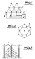
- 1 is a borehole pattern with individual boreholes 1 shown. In these holes 1 are Explosive charges with associated detonators 2 used all connected to a central control unit 3 are.
- igniters 2 are within the scope of the exemplary embodiment around electronic detonators 2 which are as in 5 are constructed in detail. So points each electronic detonator 2 an energy storage 4 in Form one or more capacitors. This Energy store 4 is followed by an electronic switch 5, at which it is within the scope of the embodiment Switching transistor is. This switching transistor 5 is with the help of a data control part or a computer unit 6 or a microchip controlled. Once this microchip or computer 6, the electronic switch 5 in the transferred conductive state, is from the energy storage 4 supplied electrical energy on associated ignition cables 7 are available, which are the most detailed Ignite explosive charge, not shown. Of course are still not essential to the invention Components of the electronic detonator 2 such as power supply and / or rectifier realized as in Detail is described in DE-OS 197 21 839.
- the central ensures Control unit 3 for the corresponding adjustment of individual detonators 2 with each other. Basically, can such a central control unit 3, of course be dispensed with, so that the individual igniters 2 at Introduction into the respective borehole 1 can be programmed (have to).
- control unit 3 enables a central one Programming the shot pattern to be set and of course also changing it, if desired should.
- the detonators 2 are corresponding to that freely programmable method already described, whereby a mineralogical and / or geological environment appropriate shot pattern, d. H. a certain firing order or a selectable firing pattern can be.
- the lowercase letters a, b, c, d and e designate boreholes 1, the first Drill hole - a - is fired first and then the drill holes follow 1 with the designation b etc.
- the lower case letters represent the firing order or firing pattern. you recognizes that three (or more) rows of boreholes with each other are networked and a cross-row ignition pattern form.
- the explosion at borehole 1 with the Marking a started as a single shot.
- This Single shot a can be made according to the borehole depth so delayed to the subsequent shots that a Movement of the masses in the first shot area possible becomes.
- FIG. 2 illustrates several opening circles that can be arranged around a symmetrical center with the designation a.
- Opposing boreholes 1 (b, c, d) are ignited in pairs, at the same time. This allows a fully effective opening of the borehole 1, which is blown up first (designation a). This is particularly evident in the section according to FIG. 3. 4 visualizes the horizontal ignition speed v ZH set according to the invention, which in the described manner is always greater than or equal to the (previously determined) rock speed v G.
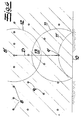
- the pre-split holes 8 ignited together or in groups. This also applies to the production wells 9. This is through related Shock wave fronts 11, 12 shown. Corresponds the shock wave front 11 to a first ignited Production well 9 '. This includes one reflected shock wave front 11 '.
- the core procedure is such that a distance D between the production borehole 9 'and the associated gap borehole 8' influences the time delay ⁇ T of the associated ignition times, taking into account the rock speeds v G as follows: ⁇ T ⁇ D / v G
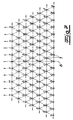
- FIG. 7 is a compared to FIG. 1st supplemented borehole pattern shown.
- the explosion marked with b follows Drill holes 1, in this case at an interval of approx. 40 to 60 msec. Of course, this depends in particular on Distance between the holes 1 to each other and the to be resolved Rock morphology.
- Blast b is followed by Holes marked c, in one time interval of approx. 3 to 10 msec compared to the boreholes b.
- the temporal ones are similar Distances to the subsequent explosions d, e, f, etc. sized.
- the last borehole 1 shown and to be blasted with the designation 1 is ignited about 90 to 100 msec after the borehole 1 with the designation a.
- the distance between the first ignited borehole 1 marked a to the last triggered borehole 1 labeled 1 is approximately 200 m.
- a horizontal ignition speed v ZH of approx. 2000 m / s is calculated from this.
- This horizontal ignition speed v ZH is significantly larger than the rock speed v G , which in the example shown does not even reach 1000 m / s. Ie the relation already explained applies: v ZH ⁇ v G ,
- the well pattern shown in Fig. 7 is designed mirror-symmetrical to an axis of symmetry S. in the Incidentally, it turns out that subsequent ignitions are distributed over at least two adjacent ignition rows, so that the already mentioned cross-row Ignition pattern results.
- the holes 1 in Broadly ignited from row to row. This means that starting with the first row continuous shock waves into the blasting area.
- Drill holes 1 again dimensioned so that when they arrive the shock wave at neighboring borehole 1 already detonated.
- This gas pressure wave arises after the implementation of the Explosives and will use one versus seismic Wave generated slower reproductive rate. Most often, this rate of reproduction is in the subsonic area while the shock wave velocity in the supersonic range (supersonic range) is located.
Landscapes
- Engineering & Computer Science (AREA)
- Life Sciences & Earth Sciences (AREA)
- Remote Sensing (AREA)
- Physics & Mathematics (AREA)
- Environmental & Geological Engineering (AREA)
- Acoustics & Sound (AREA)
- General Engineering & Computer Science (AREA)
- Geology (AREA)
- General Life Sciences & Earth Sciences (AREA)
- General Physics & Mathematics (AREA)
- Geophysics (AREA)
- Drilling And Exploitation, And Mining Machines And Methods (AREA)
- Geophysics And Detection Of Objects (AREA)
Claims (10)
- Procédé pour faire sauter des blocs de rocher ou similaires, au jour ou au fond, selon lequel on introduit dans des trous de mine (1) des charges explosives équipées chacune d'un détonateur électronique (2) puis on programme ces détonateurs (2) et les intervalles séparant leurs allumages en fonction de l'environnement minéralogique et géologique et des vitesses de propagation sismiques (VG) en résultant, ainsi qu'en tenant compte du plan de tir,
caractérisé en ce que
dans chaque trou de mine (1) est introduit un détonateur électronique de fond et un détonateur électronique de tête, programmés pour un même instant d'allumage ou des instants différents, de sorte que des fronts de détonation progressant selon des directions opposées se rencontrent à peu près au milieu de la colonne de charge avec doublage de la vitesse de détonation et transformation accélérée de la colonne de charge. - Procédé selon la revendication 1,
caractérisé en ce qu'
il utilise des détonateurs électroniques (2) dont les points d'allumage peuvent être réglés en continu et de manière exacte. - Procédé selon les revendications 1 ou 2,
caractérisé en ce que
pour augmenter l'efficacité de l'explosion, des fronts d'onde de choc individuels, partant des trous de mine (1) correspondants, interfèrent pour briser la structure de la roche à faire sauter. - Procédé selon l'une des revendications 1 à 3,
caractérisé en ce que
pour que les explosions qui se succèdent s'influencent réciproquement, on règle, en tenant compte de leur ordre successif, les décalages d'allumage entre le premier et le dernier trou de mine de manière qu'ils correspondent à une vitesse d'allumage (vitesse horizontale d'allumage VZH) au moins égale à la vitesse du son dans le rocher à faire sauter (vitesse de rocher VG) (c'est-à-dire VZH > VG). - Procédé selon une des revendications 1 à 4,
caractérisé en ce que
la vitesse du son (VG) dans le rocher à faire sauter est d'abord définie en utilisant une technique de mesure et/ou le calcul basé sur des simulations. - Procédé selon une des revendications 1 à 5,
caractérisé en ce qu'
en plus de l'onde sismique (onde sonore), une onde de pression de gaz fait suite à la transformation de l'explosif avec une vitesse de propagation inférieure à celle de l'onde sismique (vitesse de l'onde de pression de détonation), qui apporte son assistance à l'explosion. - Procédé selon une des revendications 1 à 6,
caractérisé en ce que
la vitesse de l'onde de choc et la vitesse de l'onde de pression de détonation sont accordées l'une à l'autre et se trouvent respectivement dans les zones des vitesses supersoniques et subsoniques. - Procédé selon une des revendications 1 à 7,
caractérisé en ce que
des explosions des préfendage et des explosions de production sont synchronisées de manière que des ébranlements sont neutralisés dans la zone d'explosion. - Modèle d'implantation de trous de mine (1) contenant des charges explosives et les détonateurs électriques correspondants (2) qui sont programmés selon le procédé défini par les revendications 1 à 8, pour obtenir un plan de tir souhaité, selon lequel :dans chaque trou de mine (1) sont logés un détonateur électronique de fond et un détonateur électronique de tête,il existe plusieurs lignes de trous de mine (1),les détonateurs (2) sont allumés de manière à obtenir une propagation en ligne des allumages.
- Modèle d'implantation selon la revendication 9,
caractérisé en ce que
les trous de mine (1) sont disposés selon une configuration triangulaire ou circulaire.
Applications Claiming Priority (2)
| Application Number | Priority Date | Filing Date | Title |
|---|---|---|---|
| DE19918491 | 1999-04-23 | ||
| DE19918491 | 1999-04-23 |
Publications (3)
| Publication Number | Publication Date |
|---|---|
| EP1046879A2 EP1046879A2 (fr) | 2000-10-25 |
| EP1046879A3 EP1046879A3 (fr) | 2001-04-11 |
| EP1046879B1 true EP1046879B1 (fr) | 2002-10-16 |
Family
ID=7905635
Family Applications (1)
| Application Number | Title | Priority Date | Filing Date |
|---|---|---|---|
| EP00107537A Expired - Lifetime EP1046879B1 (fr) | 1999-04-23 | 2000-04-07 | Procédé pour le sautage de masses rocheuses |
Country Status (11)
| Country | Link |
|---|---|
| US (1) | US6460462B1 (fr) |
| EP (1) | EP1046879B1 (fr) |
| AR (1) | AR023489A1 (fr) |
| AT (1) | ATE226314T1 (fr) |
| AU (1) | AU760755B2 (fr) |
| CA (1) | CA2306536C (fr) |
| DE (1) | DE50000632D1 (fr) |
| ES (1) | ES2185527T3 (fr) |
| ID (1) | ID25678A (fr) |
| NZ (1) | NZ504142A (fr) |
| PE (1) | PE20001581A1 (fr) |
Cited By (1)
| Publication number | Priority date | Publication date | Assignee | Title |
|---|---|---|---|---|
| WO2005052498A1 (fr) | 2003-11-28 | 2005-06-09 | Bohlen Handel Gmbh | Procede et dispositif permettant de faire exploser des masses rocheuses ou analogue |
Families Citing this family (23)
| Publication number | Priority date | Publication date | Assignee | Title |
|---|---|---|---|---|
| AU2002224660B2 (en) * | 2001-01-19 | 2005-09-29 | Orica Explosives Technology Pty Ltd | Method of Blasting |
| AUPR262801A0 (en) | 2001-01-19 | 2001-02-15 | Orica Explosives Technology Pty Ltd | Method of blasting |
| KR20020082501A (ko) * | 2001-03-20 | 2002-10-31 | 티앤알비 주식회사 | 천공간격, 장약량 및 발파순서를 조절한 암파쇄벤치발파방법 |
| US20050066836A1 (en) * | 2003-09-12 | 2005-03-31 | Yigal Levi | Method for controlling explosions in open mines |
| US6941870B2 (en) * | 2003-11-04 | 2005-09-13 | Advanced Initiation Systems, Inc. | Positional blasting system |
| AU2005255053B2 (en) * | 2004-06-22 | 2010-07-01 | Orica Explosives Technology Pty Ltd | Method of blasting |
| DK2210832T3 (da) * | 2005-03-11 | 2012-04-10 | Wrh Walter Reist Holding Ag | Transportindretning og rullelegeme |
| PE20090252A1 (es) * | 2007-05-15 | 2009-03-19 | Orica Explosives Tech Pty Ltd | Detonacion electronica de alta precision |
| US20120017792A1 (en) * | 2009-02-10 | 2012-01-26 | Dyno Nobel Asia Pacific Pty Limited | Method of blasting |
| PE20130051A1 (es) | 2009-09-29 | 2013-02-04 | Orica Explosives Tech Pty Ltd | Metodo para volar roca subterranea |
| US9057261B2 (en) | 2010-03-19 | 2015-06-16 | Exxonmobil Upstream Research Company | System and method for fracturing rock in tight reservoirs |
| CA2882933A1 (fr) | 2012-09-27 | 2014-04-03 | Wintershall Holding GmbH | Procede de fracturation d'une formation souterraine dans laquelle est creuse au moins un trou de forage devie |
| CN104101270A (zh) * | 2014-07-08 | 2014-10-15 | 华侨大学 | 一种地下工程中深孔爆破掏槽方法 |
| US10570736B2 (en) | 2016-06-09 | 2020-02-25 | Abb Schweiz Ag | Robot automated mining |
| PL4357726T3 (pl) | 2018-01-29 | 2025-10-06 | Dyno Nobel Inc. | Sposób i system do automatycznego ładowania otworów strzałowych |
| CN110579143B (zh) * | 2018-11-08 | 2022-05-20 | 广西建工第五建筑工程集团有限公司 | 一种坚硬岩基础定位爆破与液压胀裂联合开挖施工方法 |
| AU2019200724B1 (en) | 2019-01-15 | 2020-05-21 | DynaEnergetics Europe GmbH | Booster charge holder for an initiator system |
| WO2022099356A1 (fr) | 2020-11-10 | 2022-05-19 | Dyno Nobel Asia Pacific Pty Limited | Systèmes et procédés pour la détermination de profondeur d'eau et de profondeur d'explosif dans des trous de mine |
| CN113671026A (zh) * | 2021-07-05 | 2021-11-19 | 武汉理工大学 | 一种模拟球面波在岩体中传播的实验装置及实验方法 |
| CN113464137B (zh) * | 2021-07-15 | 2024-11-01 | 平顶山天安煤业股份有限公司十二矿 | 一种近全岩保护层煤岩混采综采方法及设备选型配套 |
| CN115263297B (zh) * | 2022-07-14 | 2024-10-18 | 紫金(长沙)工程技术有限公司 | 一种爆轰冲击水压致裂矿岩方法 |
| CN115420156B (zh) * | 2022-08-23 | 2024-04-09 | 南京理工大学 | 一种基于多药室技术的变威力防暴弹药 |
| CN117007642A (zh) * | 2023-05-30 | 2023-11-07 | 南昌大学 | 一种隧洞爆破开挖炸药能量利用效率实时监测与评估方法 |
Family Cites Families (15)
| Publication number | Priority date | Publication date | Assignee | Title |
|---|---|---|---|---|
| GB961324A (en) * | 1960-08-11 | 1964-06-17 | Dow Chemical Co | Detonation of an explosive charge |
| US3902422A (en) * | 1973-07-26 | 1975-09-02 | Du Pont | Explosive fracturing of deep rock |
| US3973497A (en) * | 1974-09-24 | 1976-08-10 | E. I. Du Pont De Nemours And Company | Directed-thrust blasting process |
| US4333684A (en) * | 1979-10-26 | 1982-06-08 | Occidental Oil Shale Inc. | Method of uniform rubblization for limited void volume blasting |
| SU1122887A1 (ru) * | 1983-06-03 | 1984-11-07 | Карагандинский политехнический институт | Способ отбойки полезных ископаемых комплектами веерных скважин |
| EG19633A (en) | 1983-12-22 | 1995-08-30 | Dynamit Nobel Ag | Process for chronologically staggered release of electronic explosive detonating device |
| MW1787A1 (en) * | 1986-04-10 | 1987-12-09 | Ici Australia Ltd | Blasting method |
| US4725991A (en) * | 1986-05-29 | 1988-02-16 | Shell Oil Company | Method for controlling blasting operations |
| GB8718202D0 (en) * | 1987-07-31 | 1987-09-09 | Du Pont Canada | Blasting system |
| US4815385A (en) * | 1987-12-16 | 1989-03-28 | The United States Of America As Represented By The Secretary Of The Army | Blast focusing method and apparatus |
| WO1991004455A1 (fr) * | 1989-09-12 | 1991-04-04 | Tsentralny Nauchno-Issledovatelsky I Proektno-Experimentalny Institut Organizatsii, Mekhanizatsii I Tekhnicheskoi Pomoschi Stroitelstvu | Procede de realisation de cavites dans un sol dur |
| JP3147895B2 (ja) * | 1990-10-30 | 2001-03-19 | 靖二 中島 | 斉発穿孔発破における穿孔間隔長決定方法 |
| US6014933A (en) * | 1993-08-18 | 2000-01-18 | Weatherford Us Holding, L.P. A Louisiana Limited Partnership | Downhole charge carrier |
| US5388521A (en) * | 1993-10-18 | 1995-02-14 | Coursen Family Trust | Method of reducing ground vibration from delay blasting |
| DE19721839A1 (de) | 1997-04-15 | 1998-10-22 | Dynamit Nobel Ag | Elektronischer Zünder |
-
2000
- 2000-04-07 EP EP00107537A patent/EP1046879B1/fr not_active Expired - Lifetime
- 2000-04-07 AT AT00107537T patent/ATE226314T1/de not_active IP Right Cessation
- 2000-04-07 ES ES00107537T patent/ES2185527T3/es not_active Expired - Lifetime
- 2000-04-07 DE DE50000632T patent/DE50000632D1/de not_active Expired - Lifetime
- 2000-04-10 PE PE2000000323A patent/PE20001581A1/es not_active Application Discontinuation
- 2000-04-13 AR ARP000101725A patent/AR023489A1/es not_active Application Discontinuation
- 2000-04-19 AU AU28890/00A patent/AU760755B2/en not_active Ceased
- 2000-04-20 NZ NZ504142A patent/NZ504142A/xx unknown
- 2000-04-24 ID IDP20000330D patent/ID25678A/id unknown
- 2000-04-24 US US09/557,228 patent/US6460462B1/en not_active Expired - Lifetime
- 2000-04-25 CA CA002306536A patent/CA2306536C/fr not_active Expired - Lifetime
Cited By (1)
| Publication number | Priority date | Publication date | Assignee | Title |
|---|---|---|---|---|
| WO2005052498A1 (fr) | 2003-11-28 | 2005-06-09 | Bohlen Handel Gmbh | Procede et dispositif permettant de faire exploser des masses rocheuses ou analogue |
Also Published As
| Publication number | Publication date |
|---|---|
| NZ504142A (en) | 2000-12-22 |
| EP1046879A2 (fr) | 2000-10-25 |
| AU760755B2 (en) | 2003-05-22 |
| PE20001581A1 (es) | 2001-02-12 |
| US6460462B1 (en) | 2002-10-08 |
| AR023489A1 (es) | 2002-09-04 |
| CA2306536C (fr) | 2006-07-18 |
| ATE226314T1 (de) | 2002-11-15 |
| ID25678A (id) | 2000-10-26 |
| DE50000632D1 (de) | 2002-11-21 |
| AU2889000A (en) | 2000-10-26 |
| ES2185527T3 (es) | 2003-05-01 |
| CA2306536A1 (fr) | 2000-10-23 |
| EP1046879A3 (fr) | 2001-04-11 |
Similar Documents
| Publication | Publication Date | Title |
|---|---|---|
| EP1046879B1 (fr) | Procédé pour le sautage de masses rocheuses | |
| DE69911154T2 (de) | Aufeinanderfolgende detonation von sprengladungen | |
| US7104326B2 (en) | Apparatus and method for severing pipe utilizing a multi-point initiation explosive device | |
| Leng et al. | Mechanism of the in-hole detonation wave interactions in dual initiation with electronic detonators in bench blasting operation | |
| US5388521A (en) | Method of reducing ground vibration from delay blasting | |
| DE69016318T2 (de) | Lochapparat mit Verzögerungsvorrichtung für Bohrloch. | |
| US7707939B2 (en) | Method of blasting | |
| DE69628825T2 (de) | Verfahren zur entnahme von wasser aus einem brunnen | |
| EP2239536A2 (fr) | Système d'allumage réglable pour une tête militaire | |
| DE2630979A1 (de) | Abbauverfahren | |
| EP2824414B1 (fr) | Procédé et dispositif destinés à contrôler la performance d'un système à principe actif | |
| KR101704013B1 (ko) | 단일 및 복합 자유면에서 지연 시차를 이용하는 자유면의 위상 및 직렬 확장 발파공법 | |
| DE3408113C1 (de) | Gefechtskopf | |
| DE2841040A1 (de) | Sprengkoerper mit einer durch einen zuender zuendbaren sprengladung | |
| DE19518472C1 (de) | Verfahren zum erschütterungsarmen Ausbau von Zuggliedern eines Verpreßankers | |
| RU2725721C1 (ru) | Способ формирования заряда в скважине при комбинированной открыто-подземной разработке | |
| DE102007051345A1 (de) | Explosivstoffladung | |
| DE69931158T2 (de) | Methode zum Gebrauch einer Mehrfachhohlladung und Mehrfachhohlladung zur Durchführung der Methode | |
| Hashemi et al. | Numerical study of the effect of delay timing on blast induced rock damage | |
| DE447597C (de) | Einrichtung zur Erzeugung von Schallsignalen | |
| Rajmeny et al. | Improving pit wall stability by minimizing blast damage vis a vis rock characterization at RAM | |
| DE19849953C1 (de) | Verfahren zum Lösen von Rohstoff aus einer Rohstofflagerstätte | |
| KR20180070277A (ko) | 전자뇌관을 이용한 피복석 생산 발파공법 | |
| DE3641054A1 (de) | Zuendsystem fuer ein hohlladungsgeschoss oder einen hohlladungsgefechtskopf | |
| Sharafisafa et al. | A numerical analysis of the presplitting controlled blasting method |
Legal Events
| Date | Code | Title | Description |
|---|---|---|---|
| PUAI | Public reference made under article 153(3) epc to a published international application that has entered the european phase |
Free format text: ORIGINAL CODE: 0009012 |
|
| AK | Designated contracting states |
Kind code of ref document: A2 Designated state(s): AT BE CH CY DE DK ES FI FR GB GR IE IT LI LU MC NL PT SE |
|
| AX | Request for extension of the european patent |
Free format text: AL;LT;LV;MK;RO;SI |
|
| PUAL | Search report despatched |
Free format text: ORIGINAL CODE: 0009013 |
|
| AK | Designated contracting states |
Kind code of ref document: A3 Designated state(s): AT BE CH CY DE DK ES FI FR GB GR IE IT LI LU MC NL PT SE |
|
| AX | Request for extension of the european patent |
Free format text: AL;LT;LV;MK;RO;SI |
|
| RIC1 | Information provided on ipc code assigned before grant |
Free format text: 7F 42D 1/00 A, 7F 42D 1/055 B, 7G 01V 1/13 B |
|
| 17P | Request for examination filed |
Effective date: 20010908 |
|
| AKX | Designation fees paid |
Free format text: AT BE CH CY DE DK ES FI FR GB GR IE IT LI LU MC NL PT SE |
|
| 17Q | First examination report despatched |
Effective date: 20011206 |
|
| GRAG | Despatch of communication of intention to grant |
Free format text: ORIGINAL CODE: EPIDOS AGRA |
|
| GRAG | Despatch of communication of intention to grant |
Free format text: ORIGINAL CODE: EPIDOS AGRA |
|
| GRAH | Despatch of communication of intention to grant a patent |
Free format text: ORIGINAL CODE: EPIDOS IGRA |
|
| GRAH | Despatch of communication of intention to grant a patent |
Free format text: ORIGINAL CODE: EPIDOS IGRA |
|
| GRAA | (expected) grant |
Free format text: ORIGINAL CODE: 0009210 |
|
| AK | Designated contracting states |
Kind code of ref document: B1 Designated state(s): AT BE CH CY DE DK ES FI FR GB GR IE IT LI LU MC NL PT SE |
|
| PG25 | Lapsed in a contracting state [announced via postgrant information from national office to epo] |
Ref country code: IT Free format text: LAPSE BECAUSE OF FAILURE TO SUBMIT A TRANSLATION OF THE DESCRIPTION OR TO PAY THE FEE WITHIN THE PRESCRIBED TIME-LIMIT;WARNING: LAPSES OF ITALIAN PATENTS WITH EFFECTIVE DATE BEFORE 2007 MAY HAVE OCCURRED AT ANY TIME BEFORE 2007. THE CORRECT EFFECTIVE DATE MAY BE DIFFERENT FROM THE ONE RECORDED. Effective date: 20021016 Ref country code: IE Free format text: LAPSE BECAUSE OF FAILURE TO SUBMIT A TRANSLATION OF THE DESCRIPTION OR TO PAY THE FEE WITHIN THE PRESCRIBED TIME-LIMIT Effective date: 20021016 Ref country code: NL Free format text: LAPSE BECAUSE OF FAILURE TO SUBMIT A TRANSLATION OF THE DESCRIPTION OR TO PAY THE FEE WITHIN THE PRESCRIBED TIME-LIMIT Effective date: 20021016 Ref country code: GR Free format text: LAPSE BECAUSE OF FAILURE TO SUBMIT A TRANSLATION OF THE DESCRIPTION OR TO PAY THE FEE WITHIN THE PRESCRIBED TIME-LIMIT Effective date: 20021016 |
|
| REF | Corresponds to: |
Ref document number: 226314 Country of ref document: AT Date of ref document: 20021115 Kind code of ref document: T |
|
| REG | Reference to a national code |
Ref country code: GB Ref legal event code: FG4D Free format text: NOT ENGLISH |
|
| REG | Reference to a national code |
Ref country code: CH Ref legal event code: EP |
|
| REG | Reference to a national code |
Ref country code: IE Ref legal event code: FG4D Free format text: GERMAN |
|
| REF | Corresponds to: |
Ref document number: 50000632 Country of ref document: DE Date of ref document: 20021121 |
|
| PG25 | Lapsed in a contracting state [announced via postgrant information from national office to epo] |
Ref country code: PT Free format text: LAPSE BECAUSE OF FAILURE TO SUBMIT A TRANSLATION OF THE DESCRIPTION OR TO PAY THE FEE WITHIN THE PRESCRIBED TIME-LIMIT Effective date: 20030116 Ref country code: DK Free format text: LAPSE BECAUSE OF FAILURE TO SUBMIT A TRANSLATION OF THE DESCRIPTION OR TO PAY THE FEE WITHIN THE PRESCRIBED TIME-LIMIT Effective date: 20030116 |
|
| REG | Reference to a national code |
Ref country code: CH Ref legal event code: NV Representative=s name: KELLER & PARTNER PATENTANWAELTE AG |
|
| GBT | Gb: translation of ep patent filed (gb section 77(6)(a)/1977) |
Effective date: 20030203 |
|
| PGFP | Annual fee paid to national office [announced via postgrant information from national office to epo] |
Ref country code: AT Payment date: 20030319 Year of fee payment: 4 |
|
| NLV1 | Nl: lapsed or annulled due to failure to fulfill the requirements of art. 29p and 29m of the patents act | ||
| PG25 | Lapsed in a contracting state [announced via postgrant information from national office to epo] |
Ref country code: LU Free format text: LAPSE BECAUSE OF NON-PAYMENT OF DUE FEES Effective date: 20030407 Ref country code: CY Free format text: LAPSE BECAUSE OF FAILURE TO SUBMIT A TRANSLATION OF THE DESCRIPTION OR TO PAY THE FEE WITHIN THE PRESCRIBED TIME-LIMIT Effective date: 20030407 |
|
| PG25 | Lapsed in a contracting state [announced via postgrant information from national office to epo] |
Ref country code: MC Free format text: LAPSE BECAUSE OF NON-PAYMENT OF DUE FEES Effective date: 20030430 Ref country code: BE Free format text: LAPSE BECAUSE OF NON-PAYMENT OF DUE FEES Effective date: 20030430 |
|
| REG | Reference to a national code |
Ref country code: ES Ref legal event code: FG2A Ref document number: 2185527 Country of ref document: ES Kind code of ref document: T3 |
|
| ET | Fr: translation filed | ||
| PLBQ | Unpublished change to opponent data |
Free format text: ORIGINAL CODE: EPIDOS OPPO |
|
| REG | Reference to a national code |
Ref country code: IE Ref legal event code: FD4D Ref document number: 1046879E Country of ref document: IE |
|
| PLBI | Opposition filed |
Free format text: ORIGINAL CODE: 0009260 |
|
| PLAX | Notice of opposition and request to file observation + time limit sent |
Free format text: ORIGINAL CODE: EPIDOSNOBS2 |
|
| 26 | Opposition filed |
Opponent name: BICKFORD, DAVEY Effective date: 20030716 |
|
| BERE | Be: lapsed |
Owner name: *ROBOTH VERTRIEBSG.- M.B.H. Effective date: 20030430 |
|
| PLBB | Reply of patent proprietor to notice(s) of opposition received |
Free format text: ORIGINAL CODE: EPIDOSNOBS3 |
|
| PG25 | Lapsed in a contracting state [announced via postgrant information from national office to epo] |
Ref country code: AT Free format text: LAPSE BECAUSE OF NON-PAYMENT OF DUE FEES Effective date: 20040407 |
|
| PG25 | Lapsed in a contracting state [announced via postgrant information from national office to epo] |
Ref country code: CH Free format text: LAPSE BECAUSE OF NON-PAYMENT OF DUE FEES Effective date: 20040430 Ref country code: LI Free format text: LAPSE BECAUSE OF NON-PAYMENT OF DUE FEES Effective date: 20040430 |
|
| RAP2 | Party data changed (patent owner data changed or rights of a patent transferred) |
Owner name: ORICA EXPLOSIVES TECHNOLOGY PTY LTD |
|
| REG | Reference to a national code |
Ref country code: CH Ref legal event code: PL |
|
| REG | Reference to a national code |
Ref country code: GB Ref legal event code: 732E |
|
| REG | Reference to a national code |
Ref country code: FR Ref legal event code: TP |
|
| PLCK | Communication despatched that opposition was rejected |
Free format text: ORIGINAL CODE: EPIDOSNREJ1 |
|
| PLBN | Opposition rejected |
Free format text: ORIGINAL CODE: 0009273 |
|
| STAA | Information on the status of an ep patent application or granted ep patent |
Free format text: STATUS: OPPOSITION REJECTED |
|
| 27O | Opposition rejected |
Effective date: 20070710 |
|
| REG | Reference to a national code |
Ref country code: FR Ref legal event code: PLFP Year of fee payment: 17 |
|
| REG | Reference to a national code |
Ref country code: FR Ref legal event code: PLFP Year of fee payment: 18 |
|
| REG | Reference to a national code |
Ref country code: FR Ref legal event code: PLFP Year of fee payment: 19 |
|
| PGFP | Annual fee paid to national office [announced via postgrant information from national office to epo] |
Ref country code: GB Payment date: 20180329 Year of fee payment: 19 |
|
| PGFP | Annual fee paid to national office [announced via postgrant information from national office to epo] |
Ref country code: FR Payment date: 20180327 Year of fee payment: 19 |
|
| PGFP | Annual fee paid to national office [announced via postgrant information from national office to epo] |
Ref country code: FI Payment date: 20180410 Year of fee payment: 19 Ref country code: DE Payment date: 20180327 Year of fee payment: 19 Ref country code: ES Payment date: 20180503 Year of fee payment: 19 |
|
| PGFP | Annual fee paid to national office [announced via postgrant information from national office to epo] |
Ref country code: SE Payment date: 20180411 Year of fee payment: 19 |
|
| REG | Reference to a national code |
Ref country code: DE Ref legal event code: R119 Ref document number: 50000632 Country of ref document: DE |
|
| REG | Reference to a national code |
Ref country code: SE Ref legal event code: EUG |
|
| GBPC | Gb: european patent ceased through non-payment of renewal fee |
Effective date: 20190407 |
|
| PG25 | Lapsed in a contracting state [announced via postgrant information from national office to epo] |
Ref country code: DE Free format text: LAPSE BECAUSE OF NON-PAYMENT OF DUE FEES Effective date: 20191101 Ref country code: GB Free format text: LAPSE BECAUSE OF NON-PAYMENT OF DUE FEES Effective date: 20190407 Ref country code: SE Free format text: LAPSE BECAUSE OF NON-PAYMENT OF DUE FEES Effective date: 20190408 Ref country code: FI Free format text: LAPSE BECAUSE OF NON-PAYMENT OF DUE FEES Effective date: 20190407 |
|
| PG25 | Lapsed in a contracting state [announced via postgrant information from national office to epo] |
Ref country code: FR Free format text: LAPSE BECAUSE OF NON-PAYMENT OF DUE FEES Effective date: 20190430 |
|
| REG | Reference to a national code |
Ref country code: ES Ref legal event code: FD2A Effective date: 20200828 |
|
| PG25 | Lapsed in a contracting state [announced via postgrant information from national office to epo] |
Ref country code: ES Free format text: LAPSE BECAUSE OF NON-PAYMENT OF DUE FEES Effective date: 20190408 |